1995 JEEP YJ cooling
[x] Cancel search: coolingPage 1352 of 2158
(10) Install the A/C compressor (if equipped) and
generator bracket assembly.
(11) Install the engine fan and hub assembly and
shroud.
(12) Install the serpentine drive belt and tighten to
obtain the specified tension.
(13) Connect negative cable to battery.
TIMING CASE COVER OIL SEAL REPLACEMENT
This procedure is done with the timing case cover
installed.
(1) Disconnect negative cable from battery.
(2) Remove the serpentine drive belt.
(3) Remove the vibration damper.
(4) Remove the radiator shroud.
(5) Carefully remove the oil seal. Make sure seal
bore is clean.
(6) Position the replacement oil seal on Timing
Case Cover Alignment and Seal Installation Tool
6139 with seal open end facing inward. Apply a light
film of Perfect Seal, or equivalent, on the outside di-
ameter of the seal. Lightly coat the crankshaft with
engine oil.
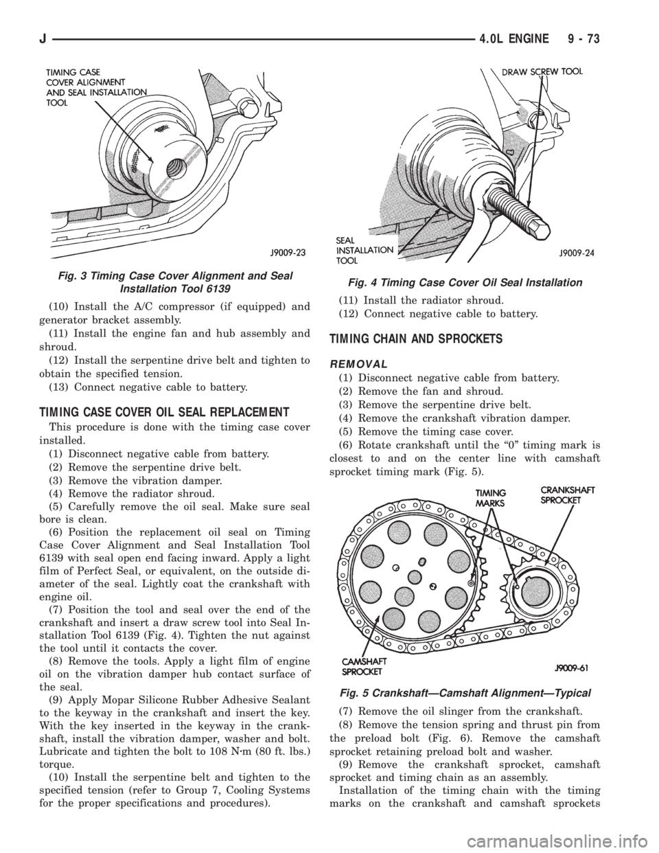
(7) Position the tool and seal over the end of the
crankshaft and insert a draw screw tool into Seal In-
stallation Tool 6139 (Fig. 4). Tighten the nut against
the tool until it contacts the cover.
(8) Remove the tools. Apply a light film of engine
oil on the vibration damper hub contact surface of
the seal.
(9) Apply Mopar Silicone Rubber Adhesive Sealant
to the keyway in the crankshaft and insert the key.
With the key inserted in the keyway in the crank-
shaft, install the vibration damper, washer and bolt.
Lubricate and tighten the bolt to 108 Nzm (80 ft. lbs.)
torque.
(10) Install the serpentine belt and tighten to the
specified tension (refer to Group 7, Cooling Systems
for the proper specifications and procedures).(11) Install the radiator shroud.
(12) Connect negative cable to battery.
TIMING CHAIN AND SPROCKETS
REMOVAL
(1) Disconnect negative cable from battery.
(2) Remove the fan and shroud.
(3) Remove the serpentine drive belt.
(4) Remove the crankshaft vibration damper.
(5) Remove the timing case cover.
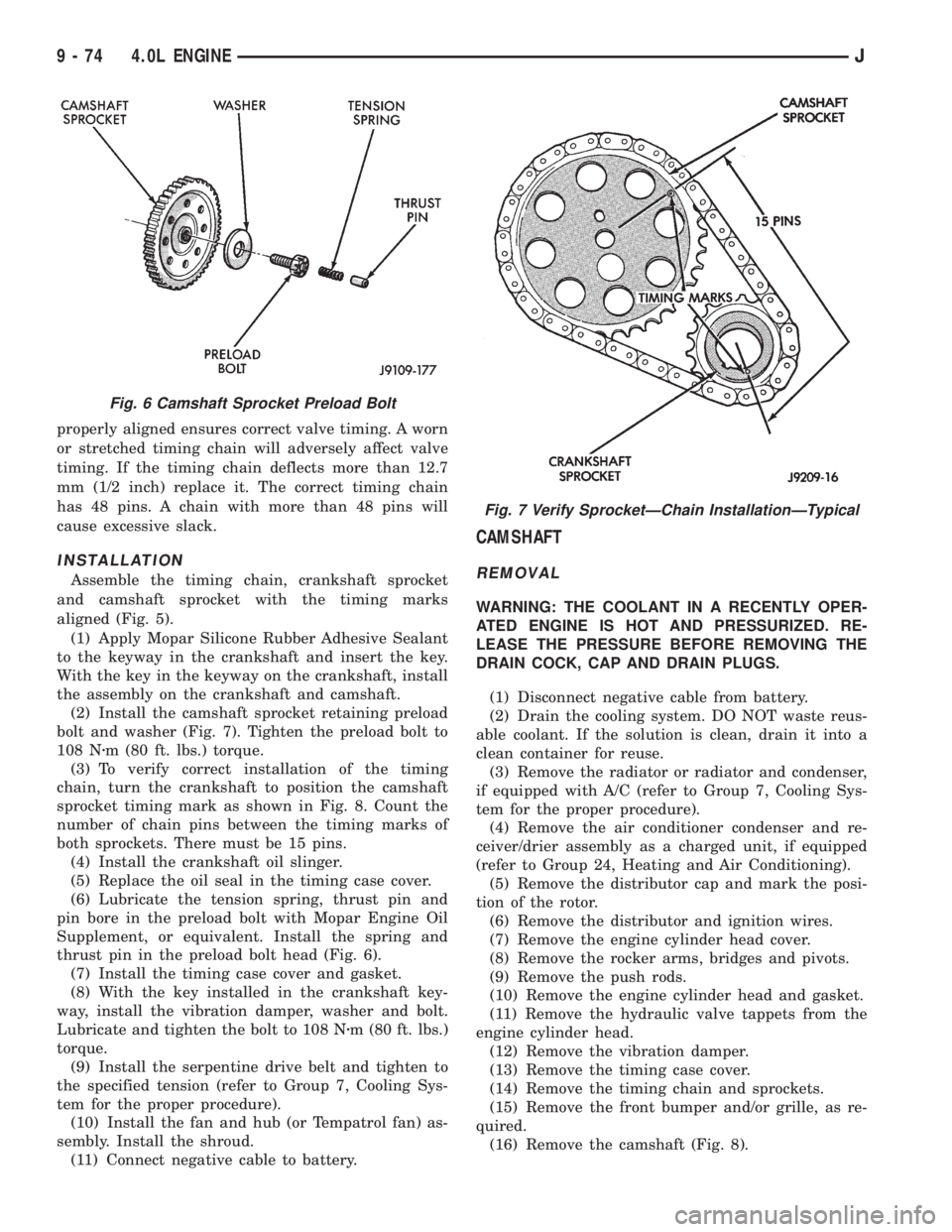
(6) Rotate crankshaft until the ``0'' timing mark is
closest to and on the center line with camshaft
sprocket timing mark (Fig. 5).
(7) Remove the oil slinger from the crankshaft.
(8) Remove the tension spring and thrust pin from
the preload bolt (Fig. 6). Remove the camshaft
sprocket retaining preload bolt and washer.
(9) Remove the crankshaft sprocket, camshaft
sprocket and timing chain as an assembly.
Installation of the timing chain with the timing
marks on the crankshaft and camshaft sprockets
Fig. 3 Timing Case Cover Alignment and Seal
Installation Tool 6139Fig. 4 Timing Case Cover Oil Seal Installation
Fig. 5 CrankshaftÐCamshaft AlignmentÐTypical
J4.0L ENGINE 9 - 73
Page 1353 of 2158
properly aligned ensures correct valve timing. A worn
or stretched timing chain will adversely affect valve
timing. If the timing chain deflects more than 12.7
mm (1/2 inch) replace it. The correct timing chain
has 48 pins. A chain with more than 48 pins will
cause excessive slack.
INSTALLATION
Assemble the timing chain, crankshaft sprocket
and camshaft sprocket with the timing marks
aligned (Fig. 5).
(1) Apply Mopar Silicone Rubber Adhesive Sealant
to the keyway in the crankshaft and insert the key.
With the key in the keyway on the crankshaft, install
the assembly on the crankshaft and camshaft.
(2) Install the camshaft sprocket retaining preload
bolt and washer (Fig. 7). Tighten the preload bolt to
108 Nzm (80 ft. lbs.) torque.
(3) To verify correct installation of the timing
chain, turn the crankshaft to position the camshaft
sprocket timing mark as shown in Fig. 8. Count the
number of chain pins between the timing marks of
both sprockets. There must be 15 pins.
(4) Install the crankshaft oil slinger.
(5) Replace the oil seal in the timing case cover.
(6) Lubricate the tension spring, thrust pin and
pin bore in the preload bolt with Mopar Engine Oil
Supplement, or equivalent. Install the spring and
thrust pin in the preload bolt head (Fig. 6).
(7) Install the timing case cover and gasket.
(8) With the key installed in the crankshaft key-
way, install the vibration damper, washer and bolt.
Lubricate and tighten the bolt to 108 Nzm (80 ft. lbs.)
torque.
(9) Install the serpentine drive belt and tighten to
the specified tension (refer to Group 7, Cooling Sys-
tem for the proper procedure).
(10) Install the fan and hub (or Tempatrol fan) as-
sembly. Install the shroud.
(11) Connect negative cable to battery.
CAMSHAFT
REMOVAL
WARNING: THE COOLANT IN A RECENTLY OPER-
ATED ENGINE IS HOT AND PRESSURIZED. RE-
LEASE THE PRESSURE BEFORE REMOVING THE
DRAIN COCK, CAP AND DRAIN PLUGS.
(1) Disconnect negative cable from battery.
(2) Drain the cooling system. DO NOT waste reus-
able coolant. If the solution is clean, drain it into a
clean container for reuse.
(3) Remove the radiator or radiator and condenser,
if equipped with A/C (refer to Group 7, Cooling Sys-
tem for the proper procedure).
(4) Remove the air conditioner condenser and re-
ceiver/drier assembly as a charged unit, if equipped
(refer to Group 24, Heating and Air Conditioning).
(5) Remove the distributor cap and mark the posi-
tion of the rotor.
(6) Remove the distributor and ignition wires.
(7) Remove the engine cylinder head cover.
(8) Remove the rocker arms, bridges and pivots.
(9) Remove the push rods.
(10) Remove the engine cylinder head and gasket.
(11) Remove the hydraulic valve tappets from the
engine cylinder head.
(12) Remove the vibration damper.
(13) Remove the timing case cover.
(14) Remove the timing chain and sprockets.
(15) Remove the front bumper and/or grille, as re-
quired.
(16) Remove the camshaft (Fig. 8).
Fig. 6 Camshaft Sprocket Preload Bolt
Fig. 7 Verify SprocketÐChain InstallationÐTypical
9 - 74 4.0L ENGINEJ
Page 1354 of 2158
INSPECTION
Inspect the cam lobes for wear.
Inspect the bearing journals for uneven wear pat-
tern or finish.
Inspect the bearings for wear.
Inspect the distributor drive gear for wear.
If the camshaft appears to have been rubbing
against the timing case cover, examine the oil pres-
sure relief holes in the rear cam journal. The oil
pressure relief holes must be free of debris.
INSTALLATION
(1) Lubricate the camshaft with Mopar Engine Oil
Supplement, or equivalent.
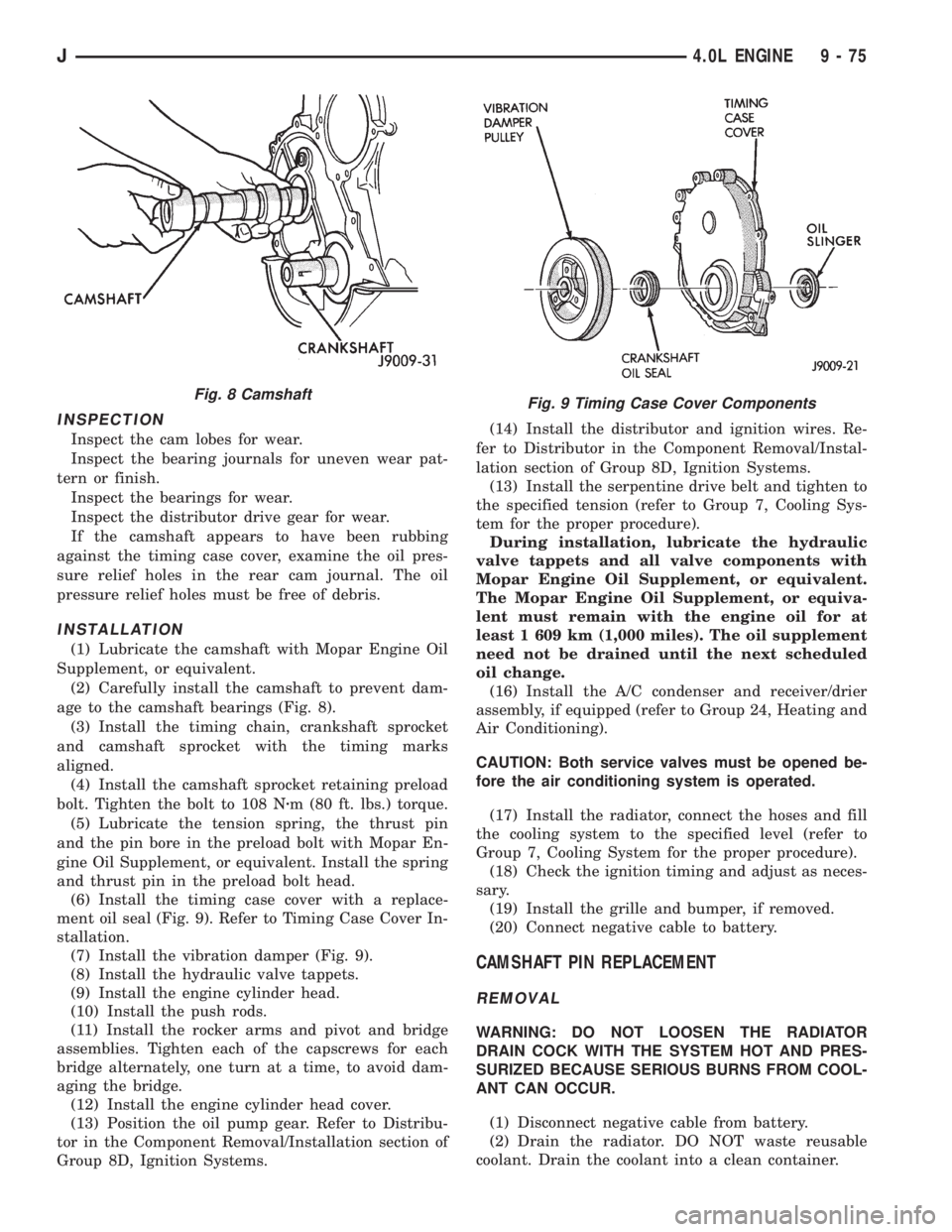
(2) Carefully install the camshaft to prevent dam-
age to the camshaft bearings (Fig. 8).
(3) Install the timing chain, crankshaft sprocket
and camshaft sprocket with the timing marks
aligned.
(4) Install the camshaft sprocket retaining preload
bolt. Tighten the bolt to 108 Nzm (80 ft. lbs.) torque.
(5) Lubricate the tension spring, the thrust pin
and the pin bore in the preload bolt with Mopar En-
gine Oil Supplement, or equivalent. Install the spring
and thrust pin in the preload bolt head.
(6) Install the timing case cover with a replace-
ment oil seal (Fig. 9). Refer to Timing Case Cover In-
stallation.
(7) Install the vibration damper (Fig. 9).
(8) Install the hydraulic valve tappets.
(9) Install the engine cylinder head.
(10) Install the push rods.
(11) Install the rocker arms and pivot and bridge
assemblies. Tighten each of the capscrews for each
bridge alternately, one turn at a time, to avoid dam-
aging the bridge.
(12) Install the engine cylinder head cover.
(13) Position the oil pump gear. Refer to Distribu-
tor in the Component Removal/Installation section of
Group 8D, Ignition Systems.(14) Install the distributor and ignition wires. Re-
fer to Distributor in the Component Removal/Instal-
lation section of Group 8D, Ignition Systems.
(13) Install the serpentine drive belt and tighten to
the specified tension (refer to Group 7, Cooling Sys-
tem for the proper procedure).
During installation, lubricate the hydraulic
valve tappets and all valve components with
Mopar Engine Oil Supplement, or equivalent.
The Mopar Engine Oil Supplement, or equiva-
lent must remain with the engine oil for at
least 1 609 km (1,000 miles). The oil supplement
need not be drained until the next scheduled
oil change.
(16) Install the A/C condenser and receiver/drier
assembly, if equipped (refer to Group 24, Heating and
Air Conditioning).
CAUTION: Both service valves must be opened be-
fore the air conditioning system is operated.
(17) Install the radiator, connect the hoses and fill
the cooling system to the specified level (refer to
Group 7, Cooling System for the proper procedure).
(18) Check the ignition timing and adjust as neces-
sary.
(19) Install the grille and bumper, if removed.
(20) Connect negative cable to battery.
CAMSHAFT PIN REPLACEMENT
REMOVAL
WARNING: DO NOT LOOSEN THE RADIATOR
DRAIN COCK WITH THE SYSTEM HOT AND PRES-
SURIZED BECAUSE SERIOUS BURNS FROM COOL-
ANT CAN OCCUR.
(1) Disconnect negative cable from battery.
(2) Drain the radiator. DO NOT waste reusable
coolant. Drain the coolant into a clean container.
Fig. 9 Timing Case Cover ComponentsFig. 8 Camshaft
J4.0L ENGINE 9 - 75
Page 1356 of 2158
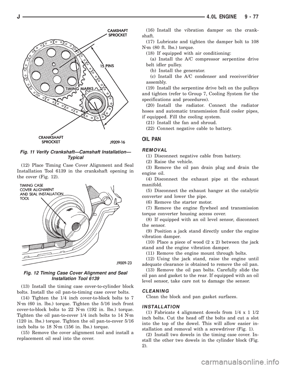
(12) Place Timing Case Cover Alignment and Seal
Installation Tool 6139 in the crankshaft opening in
the cover (Fig. 12).
(13) Install the timing case cover-to-cylinder block
bolts. Install the oil pan-to-timing case cover bolts.
(14) Tighten the 1/4 inch cover-to-block bolts to 7
Nzm (60 in. lbs.) torque. Tighten the 5/16 inch front
cover-to-block bolts to 22 Nzm (192 in. lbs.) torque.
Tighten the oil pan-to-cover 1/4 inch bolts to 14 Nzm
(120 in. lbs.) torque. Tighten the oil pan-to-cover 5/16
inch bolts to 18 Nzm (156 in. lbs.) torque.
(15) Remove the cover alignment tool and install a
replacement oil seal into the cover.(16) Install the vibration damper on the crank-
shaft.
(17) Lubricate and tighten the damper bolt to 108
Nzm (80 ft. lbs.) torque.
(18) If equipped with air conditioning:
(a) Install the A/C compressor serpentine drive
belt idler pulley.
(b) Install the generator.
(c) Install the A/C condenser and receiver/drier
assembly.
(19) Install the serpentine drive belt on the pulleys
and tighten (refer to Group 7, Cooling System for the
specifications and procedures).
(20) Install the radiator. Connect the radiator
hoses and automatic transmission fluid cooler pipes,
if equipped. Fill the cooling system.
(21) Install the fan and shroud.
(22) Connect negative cable to battery.
OIL PAN
REMOVAL
(1) Disconnect negative cable from battery.
(2) Raise the vehicle.
(3) Remove the oil pan drain plug and drain the
engine oil.
(4) Disconnect the exhaust pipe at the exhaust
manifold.
(5) Disconnect the exhaust hanger at the catalytic
converter and lower the pipe.
(6) Remove the starter motor.
(7) Remove the engine flywheel and transmission
torque converter housing access cover.
(8) If equipped with an oil level sensor, disconnect
the sensor.
(9) Position a jack stand directly under the engine
vibration damper.
(10) Place a piece of wood (2 x 2) between the jack
stand and the engine vibration damper.
(11) Remove the engine mount through bolts.
(12) Using the jack stand, raise the engine until
adequate clearance is obtained to remove the oil pan.
(13) Remove the oil pan bolts. Carefully slide the
oil pan and gasket to the rear. If equipped with an oil
level sensor, take care not to damage the sensor.
CLEANING
Clean the block and pan gasket surfaces.
INSTALLATION
(1) Fabricate 4 alignment dowels from 1/4 x 1 1/2
inch bolts. Cut the head off the bolts and cut a slot
into the top of the dowel. This will allow easier in-
stallation and removal with a screwdriver (Fig. 1).
(2) Install two dowels in the timing case cover. In-
stall the other two dowels in the cylinder block (Fig.
2).
Fig. 11 Verify CrankshaftÐCamshaft InstallationÐ
Typical
Fig. 12 Timing Case Cover Alignment and Seal
Installation Tool 6139
J4.0L ENGINE 9 - 77
Page 1371 of 2158
²The front and rear oil galley holes.
²The feed holes for the crankshaft main bearings.
Once the block has been completely cleaned, apply
Loctite PST pipe sealant with Teflon 592 to the
threads of the front and rear oil galley plugs. Tighten
the plugs to 41 Nzm (30 ft. lbs.) torque.
INSPECTIONÐCYLINDER BORE
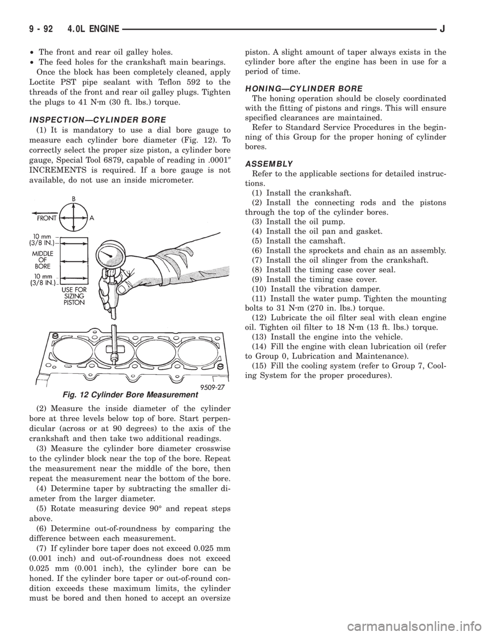
(1) It is mandatory to use a dial bore gauge to
measure each cylinder bore diameter (Fig. 12). To
correctly select the proper size piston, a cylinder bore
gauge, Special Tool 6879, capable of reading in .00019
INCREMENTS is required. If a bore gauge is not
available, do not use an inside micrometer.
(2) Measure the inside diameter of the cylinder
bore at three levels below top of bore. Start perpen-
dicular (across or at 90 degrees) to the axis of the
crankshaft and then take two additional readings.
(3) Measure the cylinder bore diameter crosswise
to the cylinder block near the top of the bore. Repeat
the measurement near the middle of the bore, then
repeat the measurement near the bottom of the bore.
(4) Determine taper by subtracting the smaller di-
ameter from the larger diameter.
(5) Rotate measuring device 90É and repeat steps
above.
(6) Determine out-of-roundness by comparing the
difference between each measurement.
(7) If cylinder bore taper does not exceed 0.025 mm
(0.001 inch) and out-of-roundness does not exceed
0.025 mm (0.001 inch), the cylinder bore can be
honed. If the cylinder bore taper or out-of-round con-
dition exceeds these maximum limits, the cylinder
must be bored and then honed to accept an oversizepiston. A slight amount of taper always exists in the
cylinder bore after the engine has been in use for a
period of time.
HONINGÐCYLINDER BORE
The honing operation should be closely coordinated
with the fitting of pistons and rings. This will ensure
specified clearances are maintained.
Refer to Standard Service Procedures in the begin-
ning of this Group for the proper honing of cylinder
bores.
ASSEMBLY
Refer to the applicable sections for detailed instruc-
tions.
(1) Install the crankshaft.
(2) Install the connecting rods and the pistons
through the top of the cylinder bores.
(3) Install the oil pump.
(4) Install the oil pan and gasket.
(5) Install the camshaft.
(6) Install the sprockets and chain as an assembly.
(7) Install the oil slinger from the crankshaft.
(8) Install the timing case cover seal.
(9) Install the timing case cover.
(10) Install the vibration damper.
(11) Install the water pump. Tighten the mounting
bolts to 31 Nzm (270 in. lbs.) torque.
(12) Lubricate the oil filter seal with clean engine
oil. Tighten oil filter to 18 Nzm (13 ft. lbs.) torque.
(13) Install the engine into the vehicle.
(14) Fill the engine with clean lubrication oil (refer
to Group 0, Lubrication and Maintenance).
(15) Fill the cooling system (refer to Group 7, Cool-
ing System for the proper procedures).
Fig. 12 Cylinder Bore Measurement
9 - 92 4.0L ENGINEJ
Page 1383 of 2158
CAUTION: When disconnecting the cruise control
connector at the throttle body, DO NOT pry the con-
nector off with pliers or screwdriver. Use finger
pressure only. Prying the connector off could break
it.
(9) Disconnect the electrical connectors. Pull the
harnesses away from the manifold.
²The throttle position sensor.
²The idle speed control motor.
²The coolant temperature sensor at the thermostat.
²The manifold air temperature sensor at the intake
manifold.
²The fuel injectors.
²The oxygen sensor.
(10) Disconnect the crankcase ventilation (CCV)
vacuum hose and manifold absolute pressure (MAP)
sensor vacuum hose connector at the intake mani-
fold.
(11) Disconnect vacuum hose from vacuum port on
the intake manifold.
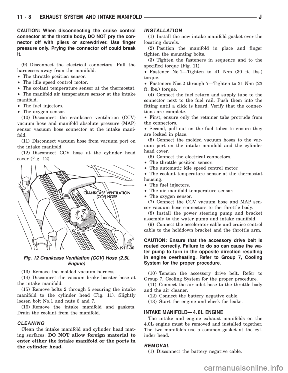
(12) Disconnect CCV hose at the cylinder head
cover (Fig. 12).
(13) Remove the molded vacuum harness.
(14) Disconnect the vacuum brake booster hose at
the intake manifold.
(15) Remove bolts 2 through 5 securing the intake
manifold to the cylinder head (Fig. 11). Slightly
loosen bolt No.1 and nuts 6 and 7.
(16) Remove the intake manifold and gaskets.
Drain the coolant from the manifold.
CLEANING
Clean the intake manifold and cylinder head mat-
ing surfaces.DO NOT allow foreign material to
enter either the intake manifold or the ports in
the cylinder head.
INSTALLATION
(1) Install the new intake manifold gasket over the
locating dowels.
(2) Position the manifold in place and finger
tighten the mounting bolts.
(3) Tighten the fasteners in sequence and to the
specified torque (Fig. 11).
²Fastener No.1ÐTighten to 41 Nzm (30 ft. lbs.)
torque.
²Fasteners Nos.2 through 7ÐTighten to 31 Nzm (23
ft. lbs.) torque.
(4) Connect the fuel return and supply tube to the
connector next to the fuel rail. Push them into the
fitting until a click is heard. Verify that the connec-
tions are complete.
²First, ensure only the retainer tabs protrude from
the connectors.
²Second, pull out on the fuel tubes to ensure they
are locked in place.
(5) Connect the molded vacuum hoses to the vac-
uum port on the intake manifold and the cylinder
head cover.
(6) Connect the electrical connectors.
²The throttle position sensor.
²The automatic idle speed control motor.
²The coolant temperature sensor at the thermostat
housing.
²The fuel injectors.
²The air manifold temperature sensor.
²The oxygen sensor.
(7) Connect the CCV vacuum hose and MAP sen-
sor vacuum hose connectors to the throttle body.
(8) Install the power steering pump and bracket
assembly to the water pump and intake manifold.
(9) Connect the accelerator cable and cruise control
cable to the holddown bracket and the throttle arm.
CAUTION: Ensure that the accessory drive belt is
routed correctly. Failure to do so can cause the wa-
ter pump to turn in the opposite direction resulting
in engine overheating. Refer to Group 7, Cooling
System for the proper procedure.
(10) Tension the accessory drive belt. Refer to
Group 7, Cooling System for the proper procedure.
(11) Connect the air inlet hose to the throttle body
and the air cleaner.
(12) Connect the battery negative cable.
(13) Start the engine and check for leaks.
INTAKE MANIFOLDÐ4.0L ENGINE
The intake and engine exhaust manifolds on the
4.0L engine must be removed and installed together.
The two manifolds use a common gasket at the cyl-
inder head.
REMOVAL
(1) Disconnect the battery negative cable.
Fig. 12 Crankcase Ventilation (CCV) Hose (2.5L
Engine)
11 - 8 EXHAUST SYSTEM AND INTAKE MANIFOLDJ
Page 1384 of 2158
(2) Remove air cleaner inlet hose from throttle
plate assembly.
(3) Remove the air cleaner assembly.
(4) Remove the throttle cable, cruise control cable
(if equipped) and the transmission line pressure ca-
ble.
(5) Disconnect all electrical connectors on the in-
take manifold.
(6) Disconnect and remove the fuel supply and re-
turn lines from the fuel rail assembly (refer to Group
14, Fuel System).
(7) Loosen the accessory drive belt (refer to Group
7, Cooling System). Loosen the tensioner.
(8) Remove the power steering pump and bracket
from the intake manifold and set aside.
(9) Remove the fuel rail and injectors (refer to
Group 14, Fuel System).
(10) Raise the vehicle.
(11) Disconnect the exhaust pipe from the engine
exhaust manifold. Discard the seal.
(12) Lower the vehicle.
(13) Remove the intake manifold and engine ex-
haust manifold.
CLEANING
Clean the mating surfaces of the cylinder head and
the manifold if the original manifold is to be in-
stalled.
If the manifold is being replaced, ensure all the fit-
ting, etc. are transferred to the replacement mani-
fold.
INSTALLATION
(1) Install a new exhaust/intake manifold gasket
over the alignment dowels on the cylinder head.
(2) Position the engine exhaust manifold to the cyl-
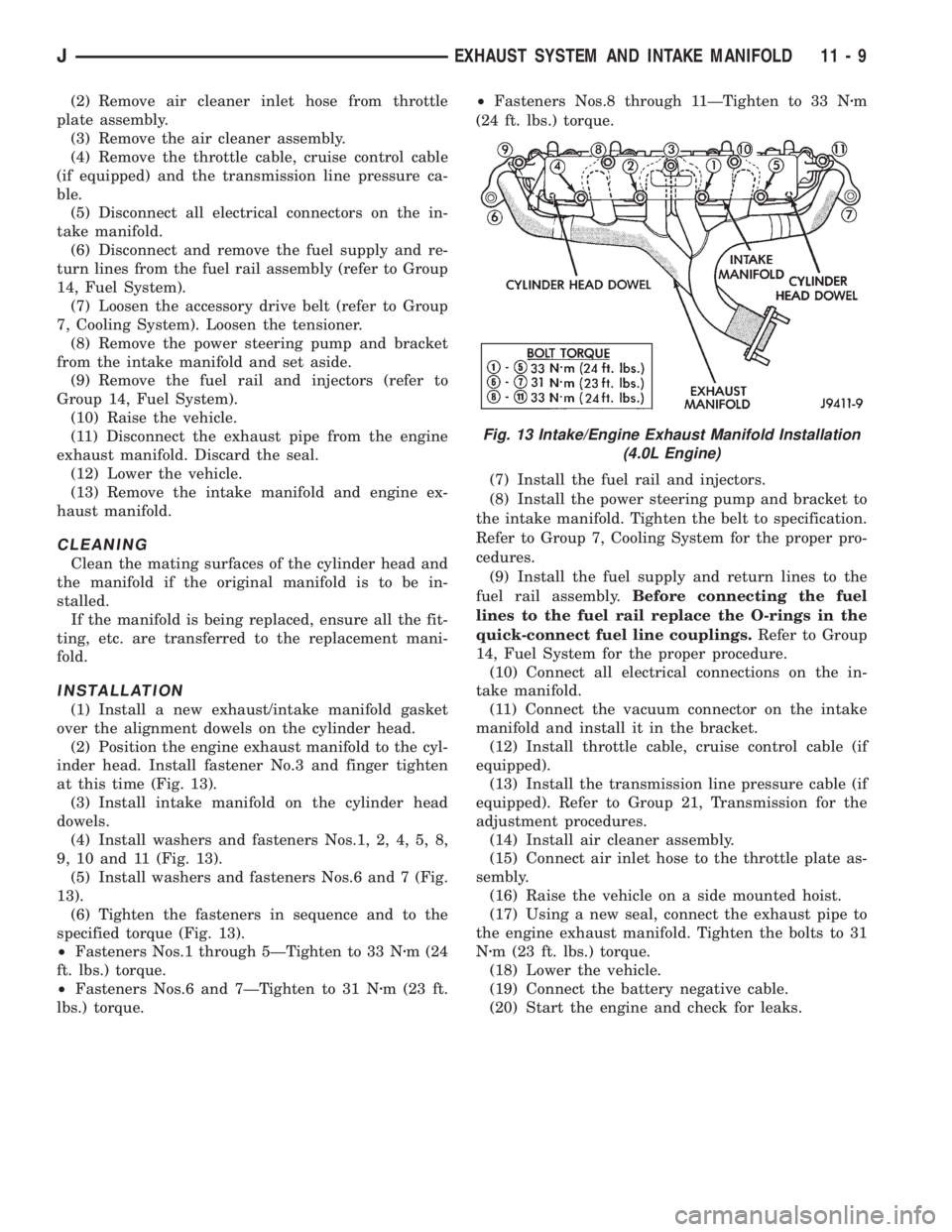
inder head. Install fastener No.3 and finger tighten
at this time (Fig. 13).
(3) Install intake manifold on the cylinder head
dowels.
(4) Install washers and fasteners Nos.1, 2, 4, 5, 8,
9, 10 and 11 (Fig. 13).
(5) Install washers and fasteners Nos.6 and 7 (Fig.
13).
(6) Tighten the fasteners in sequence and to the
specified torque (Fig. 13).
²Fasteners Nos.1 through 5ÐTighten to 33 Nzm (24
ft. lbs.) torque.
²Fasteners Nos.6 and 7ÐTighten to 31 Nzm (23 ft.
lbs.) torque.²Fasteners Nos.8 through 11ÐTighten to 33 Nzm
(24 ft. lbs.) torque.
(7) Install the fuel rail and injectors.
(8) Install the power steering pump and bracket to
the intake manifold. Tighten the belt to specification.
Refer to Group 7, Cooling System for the proper pro-
cedures.
(9) Install the fuel supply and return lines to the
fuel rail assembly.Before connecting the fuel
lines to the fuel rail replace the O-rings in the
quick-connect fuel line couplings.Refer to Group
14, Fuel System for the proper procedure.
(10) Connect all electrical connections on the in-
take manifold.
(11) Connect the vacuum connector on the intake
manifold and install it in the bracket.
(12) Install throttle cable, cruise control cable (if
equipped).
(13) Install the transmission line pressure cable (if
equipped). Refer to Group 21, Transmission for the
adjustment procedures.
(14) Install air cleaner assembly.
(15) Connect air inlet hose to the throttle plate as-
sembly.
(16) Raise the vehicle on a side mounted hoist.
(17) Using a new seal, connect the exhaust pipe to
the engine exhaust manifold. Tighten the bolts to 31
Nzm (23 ft. lbs.) torque.
(18) Lower the vehicle.
(19) Connect the battery negative cable.
(20) Start the engine and check for leaks.
Fig. 13 Intake/Engine Exhaust Manifold Installation
(4.0L Engine)
JEXHAUST SYSTEM AND INTAKE MANIFOLD 11 - 9
Page 1430 of 2158
The throttle body has an air control passage that
provides air for the engine at idle (the throttle plate
is closed). The IAC motor pintle protrudes into the
air control passage and regulates air flow through it.
Based on various sensor inputs, the powertrain con-
trol module (PCM) adjusts engine idle speed by mov-
ing the IAC motor pintle in and out of the air control
passage. The IAC motor is positioned when the igni-
tion key is turned to the On position.
A (factory adjusted) set screw is used to mechani-
cally limit the position of the throttle body throttle
plate.Never attempt to adjust the engine idle
speed using this screw.All idle speed functions are
controlled by the PCM.
IGNITION COILÐPCM OUTPUT
System voltage is supplied to the ignition coil pos-
itive terminal. The powertrain control module (PCM)
operates the ignition coil.Base (initial) ignition
timing is not adjustable.The PCM adjusts ignition
timing to meet changing engine operating conditions.
The ignition coil is located near the distributor
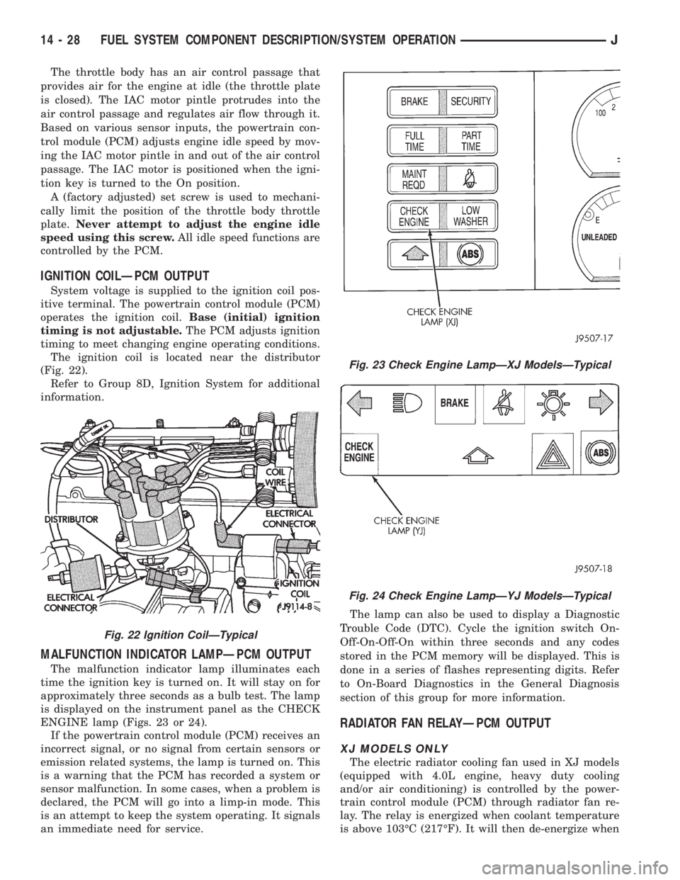
(Fig. 22).
Refer to Group 8D, Ignition System for additional
information.
MALFUNCTION INDICATOR LAMPÐPCM OUTPUT
The malfunction indicator lamp illuminates each
time the ignition key is turned on. It will stay on for
approximately three seconds as a bulb test. The lamp
is displayed on the instrument panel as the CHECK
ENGINE lamp (Figs. 23 or 24).
If the powertrain control module (PCM) receives an
incorrect signal, or no signal from certain sensors or
emission related systems, the lamp is turned on. This
is a warning that the PCM has recorded a system or
sensor malfunction. In some cases, when a problem is
declared, the PCM will go into a limp-in mode. This
is an attempt to keep the system operating. It signals
an immediate need for service.The lamp can also be used to display a Diagnostic
Trouble Code (DTC). Cycle the ignition switch On-
Off-On-Off-On within three seconds and any codes
stored in the PCM memory will be displayed. This is
done in a series of flashes representing digits. Refer
to On-Board Diagnostics in the General Diagnosis
section of this group for more information.
RADIATOR FAN RELAYÐPCM OUTPUT
XJ MODELS ONLY
The electric radiator cooling fan used in XJ models
(equipped with 4.0L engine, heavy duty cooling
and/or air conditioning) is controlled by the power-
train control module (PCM) through radiator fan re-
lay. The relay is energized when coolant temperature
is above 103ÉC (217ÉF). It will then de-energize when
Fig. 22 Ignition CoilÐTypical
Fig. 23 Check Engine LampÐXJ ModelsÐTypical
Fig. 24 Check Engine LampÐYJ ModelsÐTypical
14 - 28 FUEL SYSTEM COMPONENT DESCRIPTION/SYSTEM OPERATIONJ