1995 JEEP YJ low oil pressure
[x] Cancel search: low oil pressurePage 1816 of 2158
use shop towels or rags. Lint or foreign material from
towels or rags can interfere with valve operation.
(13) Inspect condition of lower body components.
Replace lower body if any bores are scored or cor-
roded. Replace valves, plugs or sleeves that are
scored or worn. Replace oil strainers if cut, torn or
damaged in any way.
(14) Inspect valve body springs. Replace any spring
having rusted, distorted, or collapsed coils. Measure
length of each valve body spring. Replace any spring
if free length is less than length specified in following
chart (Fig. 11).
LOWER BODY ASSEMBLY
(1) Lubricate lower body components with auto-
matic transmission fluid.
(2) Install spring and accumulator control valve in
sleeve (Fig. 11). Then install assembled components
in lower body (Fig. 9).(3) Press accumulator control valve assembly into
valve bore and install retainer (Fig. 9).
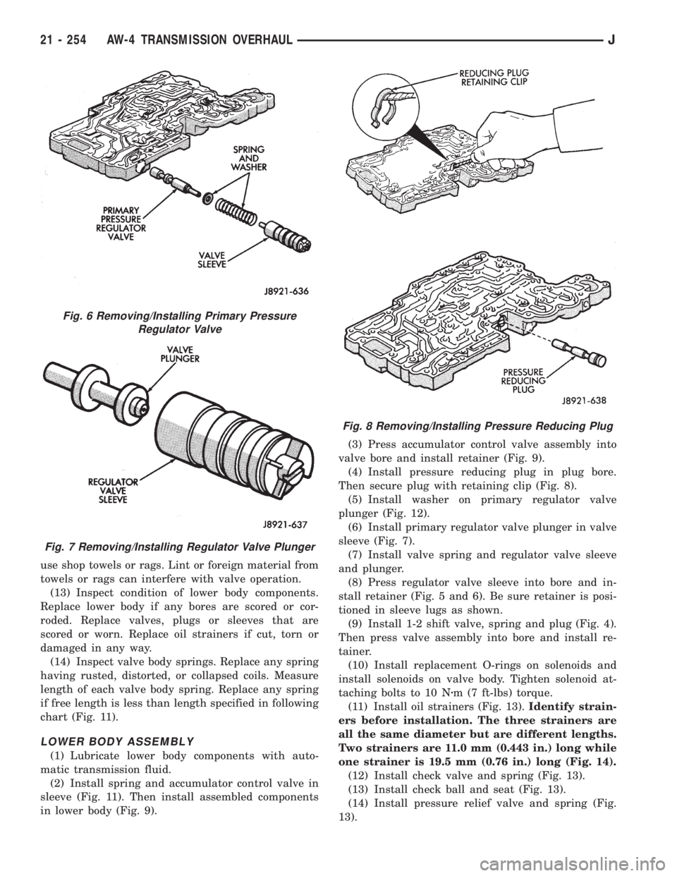
(4) Install pressure reducing plug in plug bore.
Then secure plug with retaining clip (Fig. 8).
(5) Install washer on primary regulator valve
plunger (Fig. 12).
(6) Install primary regulator valve plunger in valve
sleeve (Fig. 7).
(7) Install valve spring and regulator valve sleeve
and plunger.
(8) Press regulator valve sleeve into bore and in-
stall retainer (Fig. 5 and 6). Be sure retainer is posi-
tioned in sleeve lugs as shown.
(9) Install 1-2 shift valve, spring and plug (Fig. 4).
Then press valve assembly into bore and install re-
tainer.
(10) Install replacement O-rings on solenoids and
install solenoids on valve body. Tighten solenoid at-
taching bolts to 10 Nzm (7 ft-lbs) torque.
(11) Install oil strainers (Fig. 13).Identify strain-
ers before installation. The three strainers are
all the same diameter but are different lengths.
Two strainers are 11.0 mm (0.443 in.) long while
one strainer is 19.5 mm (0.76 in.) long (Fig. 14).
(12) Install check valve and spring (Fig. 13).
(13) Install check ball and seat (Fig. 13).
(14) Install pressure relief valve and spring (Fig.
13).
Fig. 6 Removing/Installing Primary Pressure
Regulator Valve
Fig. 7 Removing/Installing Regulator Valve Plunger
Fig. 8 Removing/Installing Pressure Reducing Plug
21 - 254 AW-4 TRANSMISSION OVERHAULJ
Page 1820 of 2158
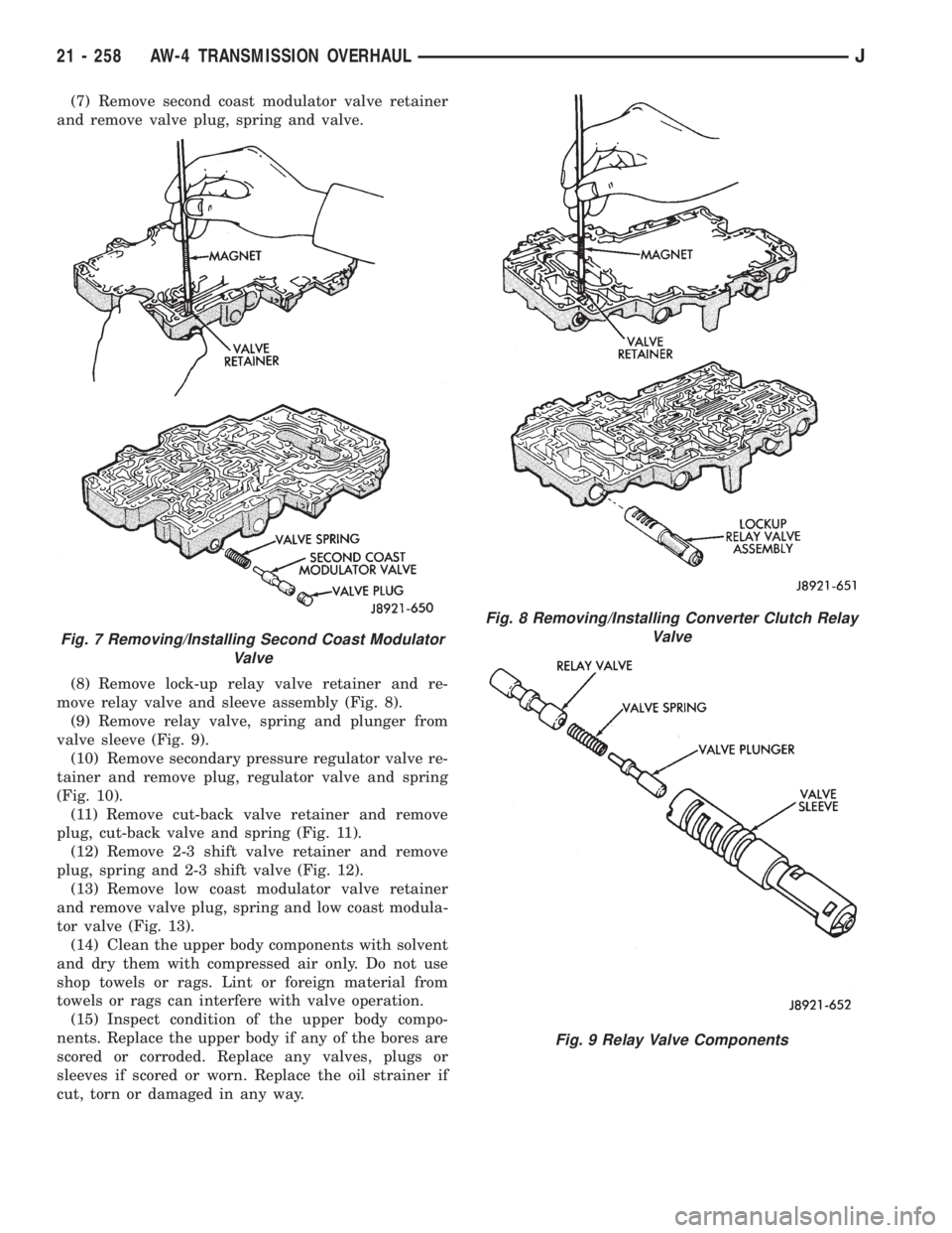
(7) Remove second coast modulator valve retainer
and remove valve plug, spring and valve.
(8) Remove lock-up relay valve retainer and re-
move relay valve and sleeve assembly (Fig. 8).
(9) Remove relay valve, spring and plunger from
valve sleeve (Fig. 9).
(10) Remove secondary pressure regulator valve re-
tainer and remove plug, regulator valve and spring
(Fig. 10).
(11) Remove cut-back valve retainer and remove
plug, cut-back valve and spring (Fig. 11).
(12) Remove 2-3 shift valve retainer and remove
plug, spring and 2-3 shift valve (Fig. 12).
(13) Remove low coast modulator valve retainer
and remove valve plug, spring and low coast modula-
tor valve (Fig. 13).
(14) Clean the upper body components with solvent
and dry them with compressed air only. Do not use
shop towels or rags. Lint or foreign material from
towels or rags can interfere with valve operation.
(15) Inspect condition of the upper body compo-
nents. Replace the upper body if any of the bores are
scored or corroded. Replace any valves, plugs or
sleeves if scored or worn. Replace the oil strainer if
cut, torn or damaged in any way.
Fig. 7 Removing/Installing Second Coast Modulator
Valve
Fig. 8 Removing/Installing Converter Clutch Relay
Valve
Fig. 9 Relay Valve Components
21 - 258 AW-4 TRANSMISSION OVERHAULJ
Page 1981 of 2158
LIFTGATE SUPPORT ROD CYLINDER DISPOSALÐ
XJ
WARNING: SAFETY GOGGLES MUST BE WORN
DURING THE DISPOSAL PROCEDURE. THE HIGH
PRESSURE GAS CHARGE IN THE SUPPORT ROD
CYLINDERS WILL BE RELEASED DURING THE
PROCEDURE.
(1) Remove the support rod cylinder(s) from the
liftgate.
(2) Position the support rod cylinder horizontally
in a vise and clamp the cylinder securely.
(3) Wrap the cylinder with 4-5 layers of shop tow-
els.
(4) Measure 1 and 1/2 inches inward from the end
of the cylinder. Mark this location on the towels with
chalk. The cylinder will be punctured at this location
to release the gas charge.
(5) Use a punch and hammer to puncture cylinder.
Force the punch through towels and into the cylinder
with a hammer. Continue striking the punch until
the gas begins to escapebut do not remove the
punch.
(6) Hold the towels and punch in position until all
the gas has escaped. Complete de-pressurization will
require about 4 to 10 seconds. After all the gas has
escaped, slowly remove the punch.
(7) Hold a towel over the hole in cylinder and press
the support rod piston all the way into the cylinder
to purge remaining oil.
(8) Remove the support rod cylinder from the vise
and discard it.
(9) If both support rod cylinders are being re-
placed, repeat this procedure for the remaining cylin-
der.
LIFTGATE SUPPORT ROD BALL STUD
REPLACEMENTÐXJ
REMOVAL
(1) Open the liftgate.
(2) Support the liftgate in the open position.
(3) Remove the retainer clip that attaches the sup-
port rod and cylinder to the ball stud.
(4) Disconnect the support rod from the ball stud.
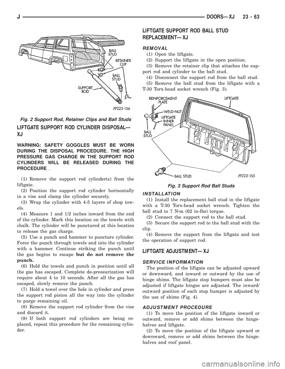
(5) Remove the ball stud from the liftgate with a
T-30 Torx-head socket wrench (Fig. 3).
INSTALLATION
(1) Install the replacement ball stud in the liftgate
with a T-30 Torx-head socket wrench. Tighten the
ball stud to 7 Nzm (62 in-lbs) torque.
(2) Connect the support rod to the ball stud.
(3) Secure the support rod to the ball stud with the
clip.
(4) Remove the support from the liftgate and test
the operation of support rod.
LIFTGATE ADJUSTMENTÐXJ
SERVICE INFORMATION
The position of the liftgate can be adjusted upward
or downward, and inward or outward by the use of
hinge shims. The liftgate stop bumpers must also be
adjusted if liftgate hinges are adjusted. The inward/
outward position of each stop bumper is adjusted by
the use of shims (Fig. 4).
ADJUSTMENT PROCEDURE
(1) To move the position of the liftgate inward or
outward, remove or add shims between the hinge-
halves and liftgate.
(2) To move the position of the liftgate upward or
downward, remove or add shims between the hinge-
halves and roof panel.
Fig. 2 Support Rod, Retainer Clips and Ball Studs
Fig. 3 Support Rod Ball Studs
JDOORSÐXJ 23 - 63
Page 2045 of 2158
HARD TOP ROOF VENTÐYJ
REMOVAL/INSTALLATION
(1) Remove the roof vent retaining screw from the
spring nut (Fig. 1).
(2) Remove the roof vent from the hard top.
(3) Position the roof vent on the hard top and in-
stall the retaining screw.
HARD TOP REPAIRÐYJ
The hard top fiberglass material can be repaired.
The required repair materials include:
²Fiberglass mat or cloth.
²Fiberglass resin and hardener.
²structural adhesive (3M brand or an equivalent
product).
²Glazing putty.
²Aluminum foil.
²Plastic spreader.
HARD TOP HOLE REPAIR
(1) Use a grinder to remove the paint and outline
the damaged area. Use a grade 24 grit disc for paint
removal.
(2) Grind the outlined surface area again to a 50
grit disc to prevent coarse scratches from appearing
in the final finish.
(3) If cracks extend from the hole, it will be neces-
sary to stop-drill the crack(s) with a 3-mm (1/8-in) di-
ameter drill bit.
(4) Position a fiberglass mat or cloth on the repair
surface area. Cut the mat to allow a 2.5-cm (1-in)
overlap of the repair surface area.
(5) Clean the repair surface area.
(6) Place the fiberglass cloth on aluminum foil.
(7) Pour the fiberglass resin into a clean container.
(8) Mix the appropriate amount of hardener and
resin. Follow the manufacturers instructions.
(9) Apply the hardener/resin mixture to both sides
of the fiberglass cloth.(10) Place the fiberglass cloth over the repair sur-
face area. Next, place the aluminum foil over the
cloth. Use a plastic spreader to smooth-out the cloth
and resin. Use firm pressure to remove air bubbles
and to smooth-out the cloth.
(11) Allow the resin to cure.
(12) Smooth-out the surface area to the contour of
the hard top with a 50-grit disc.
(13) Apply plastic filler to complete the repair. Fin-
ish smoothing the surface area with 80-grit paper.
(14) Repeat the previous step on the inside surface
area of the hard top.
(15) Featheredge the repaired surface area.
(16) Prime the repaired surface area with Ditzler
Epoxy Chromate Primer (DP-40/401), or an equiva-
lent product.
(17) Apply surface primer to the surface area.
(18) Sand the surface area for paint preparation.
After sanding, re-prime the surface area, if necessary.
(19) Prime the surface area for the color coat.
(20) Color coat the repaired surface area.
FRACTURE REPAIR
(1) Use a grinder to remove the paint (from both,
the inner and outer surface areas of the hard top)
and to outline the damaged area.
(2) Stop-drill the crack(s) with a 3-mm (1/8-in) di-
ameter drill bit.
(3) Bevel the edges of the crack(s) on both sides
with a rotary file.
The edges should be beveled on the inside
and outside of the top to ensure sufficient sur-
face area for good bonding.
(4) Complete the repairs with fiberglass cloth and
resin as described above in the hard top hole repair
procedure.
TEXTURED PAINT REPAIR
The textured paint applied to hard tops is available
from Mopar Parts sources. The paint supplied will
duplicate the original texture on the hard top.
SOFT TOP SERVICE INFORMATIONÐYJ
The soft top fabric consists of the top cover and the
side and rear curtains (Fig. 4). The top cover is sup-
ported by a tubular bow (frame) and is attached to
the upper side retainers (above the doors) with
snap-on retainers (Fig. 5).
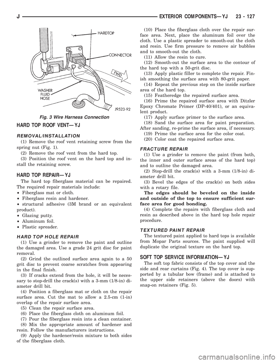
Fig. 3 Wire Harness Connection
JEXTERIOR COMPONENTSÐYJ 23 - 127
Page 2084 of 2158
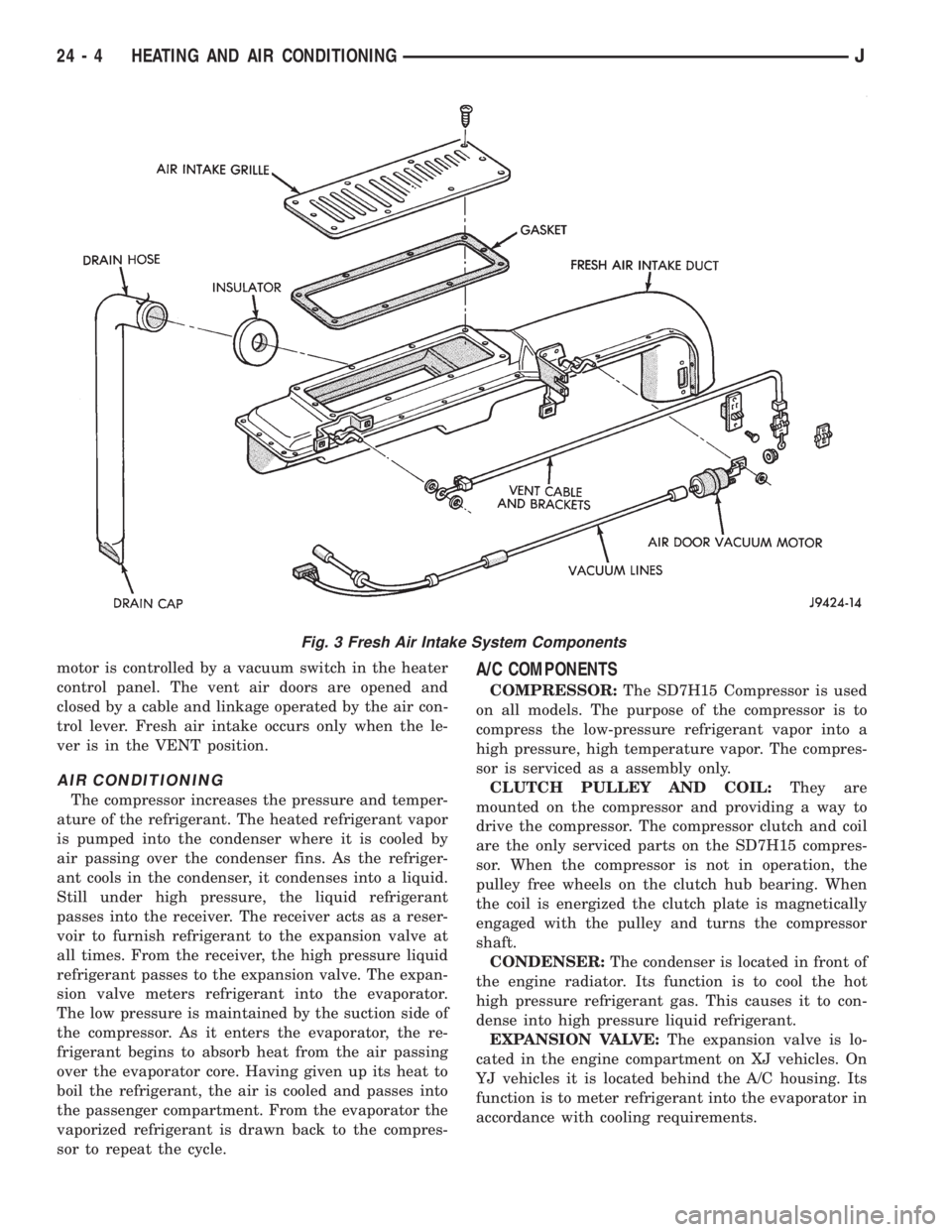
motor is controlled by a vacuum switch in the heater
control panel. The vent air doors are opened and
closed by a cable and linkage operated by the air con-
trol lever. Fresh air intake occurs only when the le-
ver is in the VENT position.
AIR CONDITIONING
The compressor increases the pressure and temper-
ature of the refrigerant. The heated refrigerant vapor
is pumped into the condenser where it is cooled by
air passing over the condenser fins. As the refriger-
ant cools in the condenser, it condenses into a liquid.
Still under high pressure, the liquid refrigerant
passes into the receiver. The receiver acts as a reser-
voir to furnish refrigerant to the expansion valve at
all times. From the receiver, the high pressure liquid
refrigerant passes to the expansion valve. The expan-
sion valve meters refrigerant into the evaporator.
The low pressure is maintained by the suction side of
the compressor. As it enters the evaporator, the re-
frigerant begins to absorb heat from the air passing
over the evaporator core. Having given up its heat to
boil the refrigerant, the air is cooled and passes into
the passenger compartment. From the evaporator the
vaporized refrigerant is drawn back to the compres-
sor to repeat the cycle.
A/C COMPONENTS
COMPRESSOR:The SD7H15 Compressor is used
on all models. The purpose of the compressor is to
compress the low-pressure refrigerant vapor into a
high pressure, high temperature vapor. The compres-
sor is serviced as a assembly only.
CLUTCH PULLEY AND COIL:They are
mounted on the compressor and providing a way to
drive the compressor. The compressor clutch and coil
are the only serviced parts on the SD7H15 compres-
sor. When the compressor is not in operation, the
pulley free wheels on the clutch hub bearing. When
the coil is energized the clutch plate is magnetically
engaged with the pulley and turns the compressor
shaft.
CONDENSER:The condenser is located in front of
the engine radiator. Its function is to cool the hot
high pressure refrigerant gas. This causes it to con-
dense into high pressure liquid refrigerant.
EXPANSION VALVE:The expansion valve is lo-
cated in the engine compartment on XJ vehicles. On
YJ vehicles it is located behind the A/C housing. Its
function is to meter refrigerant into the evaporator in
accordance with cooling requirements.
Fig. 3 Fresh Air Intake System Components
24 - 4 HEATING AND AIR CONDITIONINGJ
Page 2087 of 2158
EVAPORATOR COIL:The coil is located in the
A/C housing. Its function is to remove heat and de-
humidify the air before it enters the vehicle.
FIN SENSING CYCLING CLUTCH SWITCH:
The switch is attached to the evaporator coil with the
temperature sensing probe inserted into the coil fins.
This switch controls evaporator temperature and pre-
vents condensate water on the evaporator coil from
freezing. It does this by sending signals to the Pow-
ertrain Control Module (PCM) to cycling the com-
pressor clutch on and off. This switch is used onXJ
only.
FILTER-DRIER:The drier is used to remove any
traces of moisture from the refrigerant system. A
sight glass is located on top of the filter drier. It is
used as a diagnostic tool to observe refrigerant flow.
HIGH PRESSURE RELIEF VALVE:The valve is
located on the filter drier. The valve is used to pre-
vent excessive high pressure build of 3445 to 4135
kPa (500 to 600 psi) and above. This prevents dam-
age to the compressor and other system components.
LOW-PRESSURE HIGH-PRESSURE CUT-OFF
SWITCH:The switch is located on the filter drier
and is wired in series with compressor clutch. When
the pressure drops down to 193 kPa (28 psi) the
switch interrupts the power to the compressor clutch.
When the pressure increases above 3100 to 3375 kPa
(450 to 490 psi) the switch interrupts the power to
the compressor clutch.
THERMOSTAT:The thermostat is located in the
evaporator housing. The thermostat temperature
sensing probe is inserted into the evaporator coil. Its
function is to cycles the compressor clutch on and off.
This switch controls temperature and prevents con-
densate water on the evaporator coil from freezing.
The thermostat is used on theYJonly.
REFRIGERANT LINES:The lines are used to
carry the refrigerant between the various system
components.
SERVICE PORTS:The high pressure service port
is located on the discharge line near the compressor.
The low pressure service port is located on the suc-
tion line near the compressor. These ports are used
to attach A/C gauges. After servicing the refrigerant
system, always install service port caps.
REFRIGERANT
XJ and YJ vehicles use a new type of refrigerant
called R-134a. It is a non-toxic, non-flammable, clear
color-less liquified gas.
R-134a refrigerant is not compatible with R-12 re-
frigerant. A small amount of R-12 in a R-134a system
will cause compressor failure, oil sludge or poor air
conditioning performance.R-134a refrigerant requires a special type of com-
pressor oil (SP20 PAG). When adding oil, make sure
that it is designed to be used in a R-134a system and
the SD7H15 compressor.
Service ports have been designed to ensure that
the system is not accidentally filled with R-12 refrig-
erant.
REFRIGERANT EQUIPMENT
WARNING: EYE PROTECTION MUST BE USED
WHEN SERVICING AN AIR CONDITIONING REFRIG-
ERANT SYSTEM. TURN OFF (ROTATE CLOCKWISE)
ALL VALVES ON THE EQUIPMENT BEING USED
BEFORE PROCEEDING WITH THIS OPERATION.
PERSONNEL INJURY CAN RESULT.
Chrysler Corporation recommends a (R-134a) recy-
cling device that meets SAE standard J2210 be used
when servicing the refrigerant system. Contact an
automotive service equipment supplier for refrigerant
recycling equipment that is available in your area.
Refer to the operating instructions provided with the
recycling equipment for proper operation.
MANIFOLD GAUGE SET
CAUTION: DO NOT use an R-12 manifold gauge set
on an R-134a system. The refrigerants are not com-
patible and system damage will result.
A manifold gauge set (Fig. 1) may be needed in
conjunction with the charging and or recovery/recy-
cling device. The service hoses on the gauge set being
used should have manual (turn wheel) or automatic
back flow valves at the service port connector ends.
This will prevent refrigerant from being release into
the atmosphere.
LOW PRESSURE GAUGE HOSE
The low pressure hose (BLUE with BLACK STRIP)
should be attached to the charging/service port. This
port is located at the right front of the engine com-
partment in the condenser-to-evaporator line.
HIGH PRESSURE GAUGE HOSE
The high pressure hose (RED with BLACK STRIP)
should be attached to the discharge/service port. This
port is located on the compressor plumbing or mani-
fold.
RECOVERY/RECYCLING/EVACUATION/
CHARGING HOSE
The center manifold hose (YELLOW or WHITE
with BLACK STRIP) is used to recover, evacuate and
charge the refrigerant system. When the low or high
pressure valves on the manifold gauge set are
opened, the refrigerant in the system will escape
through this hose.
JHEATING AND AIR CONDITIONING 24 - 7
Page 2089 of 2158
WARNINGS, CAUTIONS AND SERVICE PRECAUTIONS
WARNINGS
WARNING: THE AIR CONDITIONING SYSTEM CON-
TAINS REFRIGERANT UNDER HIGH PRESSURE.
SEVERE PERSONAL INJURY MAY RESULT FROM
IMPROPER SERVICE PROCEDURES. REPAIRS
SHOULD ONLY BE PERFORMED BY QUALIFIED
SERVICE PERSONNEL.
WARNING: AVOID BREATHING A/C REFRIGERANT
AND LUBRICANT VAPOR OR MIST. EXPOSURE MAY
IRRITATE EYES, NOSE AND/OR THROAT. WEAR
EYE PROTECTION WHEN SERVICING THE AIR
CONDITIONING REFRIGERANT SYSTEM. SERIOUS
EYE INJURY CAN RESULT FROM EYE CONTACT
WITH REFRIGERANT. IF EYE CONTACT IS MADE,
SEEK MEDICAL ATTENTION IMMEDIATELY.
WARNING: DO NOT EXPOSE REFRIGERANT TO
OPEN FLAME. POISONOUS GAS IS CREATED
WHEN REFRIGERANT IS BURNED. AN ELEC-
TRONIC TYPE LEAK DETECTOR IS RECOM-
MENDED.
WARNING: IF ACCIDENTAL SYSTEM DISCHARGE
OCCURS, VENTILATE THE WORK AREA BEFORE
RESUMING SERVICE. LARGE AMOUNTS OF RE-
FRIGERANT RELEASED IN A CLOSED WORK AREA
WILL DISPLACE THE OXYGEN AND CAUSE SUFFO-
CATION.
WARNING: THE EVAPORATION RATE OF (R-134A)
REFRIGERANT AT AVERAGE TEMPERATURE AND
ALTITUDE IS EXTREMELY HIGH. AS A RESULT,
ANYTHING THAT COMES IN CONTACT WITH THE
REFRIGERANT WILL FREEZE. ALWAYS PROTECT
SKIN OR DELICATE OBJECTS FROM DIRECT CON-
TACT WITH REFRIGERANT.
WARNING: R-134A SERVICE EQUIPMENT OR VEHI-
CLE A/C SYSTEM SHOULD NOT BE PRESSURE
TESTED OR LEAK TESTED WITH COMPRESSED
AIR. SOME MIXTURES OF AIR AND R-134A HAVE
BEEN SHOWN TO BE COMBUSTIBLE AT ELEVATED
PRESSURES. THESE MIXTURES ARE POTENTIALLY
DANGEROUS AND MAY RESULT IN FIRE OR EX-
PLOSION CAUSING INJURY OR PROPERTY DAM-
AGE.
CAUTIONS
CAUTION: Liquid refrigerant is corrosive to metal
surfaces. Follow the operating instructions supplied
with equipment being used.
CAUTION: DO NOT use R-12 equipment or parts on
the R-134a system. Damage to the system will re-
sult.
CAUTION: Never add R-12 to a system designed to
use R-134a. Damage to the system will result.
CAUTION: R-12 compressor oil can not be mixed
with the R-134a compressor oil. They ARE NOT
compatible.
CAUTION: Do not over charge refrigerant system.
This will cause excessive compressor head pres-
sure and can cause noise and system failure.
SERVICE PRECAUTIONS
Recover the refrigerant before opening any fitting
or connection. Open fittings with caution even after
the system has been discharged. Never open or
loosen a connection before recovering the refrigerant.
The A/C system must always be evacuated before
charging.
DO NOT open the refrigerant system or uncap a
replacement component until you are ready to service
the system. This will prevent contamination in the
system.
Before disconnecting a component clean the outside
of the fittings thoroughly to prevent contamination
entering the system.
Immediately after disconnecting a component from
the system, seal the open fittings with a cap or plug.
Before connecting an open fitting always install a
new seal/gasket. Coat the fitting and seal with clean
refrigerant oil before connecting.
When installing a refrigerant line avoid sharp
bends. Position the lines away from the exhaust or
any sharp edges which may chafe the line.
Tighten fittings only to the specified torque. The
aluminum fittings used in the A/C system will not
tolerate over tightening.
When disconnecting a fitting use a wrench on both
halves of the fitting. This will prevent twisting of the
refrigerant lines or tubes.
Refrigerant oil absorbs moisture from the atmo-
sphere if left uncapped. DO NOT open a container of
JHEATING AND AIR CONDITIONING 24 - 9
Page 2090 of 2158
oil until you are ready to use it. Install the cap im-
mediately after using. Store the oil only in a clean
moisture-free container.
Keep service tools and the work area clean. Con-
tamination of A/C system through careless work hab-
its must be avoided.
COOLING SYSTEM
To maintain the performance level of the heating/
air conditioning system, the engine cooling system
must be properly maintained.
The use of a bug screen is not recommended. Any
obstructions in front of the radiator or condenser can
reduce the performance of the A/C and cooling sys-
tem. If a bug screen is used it must be cleaned fre-
quently.
COOLANT PRECAUTIONS
WARNING: ANTIFREEZE IS AN ETHYLENE GLYCOL
BASE COOLANT AND IS HARMFUL IF SWAL-
LOWED OR INHALED. IF SWALLOWED, DRINK
TWO GLASSES OF WATER AND INDUCE VOMIT-
ING. IF INHALED, MOVE TO FRESH AIR AREA.
SEEK MEDICAL ATTENTION IMMEDIATELY.
WARNING: WASH SKIN AND CLOTHING THOR-
OUGHLY AFTER COMING IN CONTACT WITH ETH-
YLENE GLYCOL.
WARNING: KEEP OUT OF REACH OF CHILDREN
AND PETS.
WARNING: DO NOT OPEN A COOLING SYSTEM
WHEN THE ENGINE IS AT RUNNING TEMPERA-
TURE. PERSONAL INJURY CAN RESULT.WARNING: DO NOT STORE IN OPEN OR UN-
MARKED CONTAINERS.
WARNING: HOT ENGINE COOLANT CAN CAUSE
SEVERE BURNS. DO NOT OPEN THE RADIATOR
DRAIN COCK WHEN THE COOLING SYSTEM IS
HOT AND PRESSURIZED. ALLOW THE COOLANT
TO DECREASE TO ROOM TEMPERATURE BEFORE
STARTING REPAIR OPERATIONS.
The engine cooling system is designed to develop
internal pressure of 97 to 124 kPa (14 to 18 psi). Al-
low the vehicle 15 minutes to cool down (or until a
safe temperature and pressure are attained) before
opening the cooling system. Refer to Group 7, Cooling
System.REFRIGERANT HOSES/TUBES PRECAUTIONS
Kinks or sharp bends in the refrigerant tubing or
hoses will reduce the capacity of the entire system.
High pressures are produced in the system when it is
operating. Extreme care must be exercised to make
sure that all connections are pressure tight. Dirt and
moisture can enter the system when it is opened for
repair.
A good rule for the flexible hose lines is to keep the
radius of all bends at least 10 times the diameter of
the hose. Sharp bends will reduce the flow of refrig-
erant. The flexible hose lines should be routed so
they are at least 80 mm (3 inches) from the exhaust
manifold. It is a good practice to inspect all flexible
hose lines at least once a year to make sure they are
in good condition and properly routed.
24 - 10 HEATING AND AIR CONDITIONINGJ