1995 JEEP YJ low oil pressure
[x] Cancel search: low oil pressurePage 1363 of 2158
SIDE CLEARANCE MEASUREMENT
Slide snug-fitting feeler gauge between the connect-
ing rod and crankshaft journal flange. Refer to En-
gine Specifications for the proper clearance. Replace
the connecting rod if the side clearance is not within
specification.
PISTON FITTING
BORE GAUGE METHOD
(1) To correctly select the proper size piston, a cyl-
inder bore gauge, Special Tool 6879 or equivalent, ca-
pable of reading in .00019INCREMENTS with gauge
ring Special Tool 6884 is required. If a bore gauge is
not available, do not use an inside micrometer.
(2) Set the bore gauge to the gauge ring and zero
gauge.
(3) Remove gauge from ring and check cylinder as
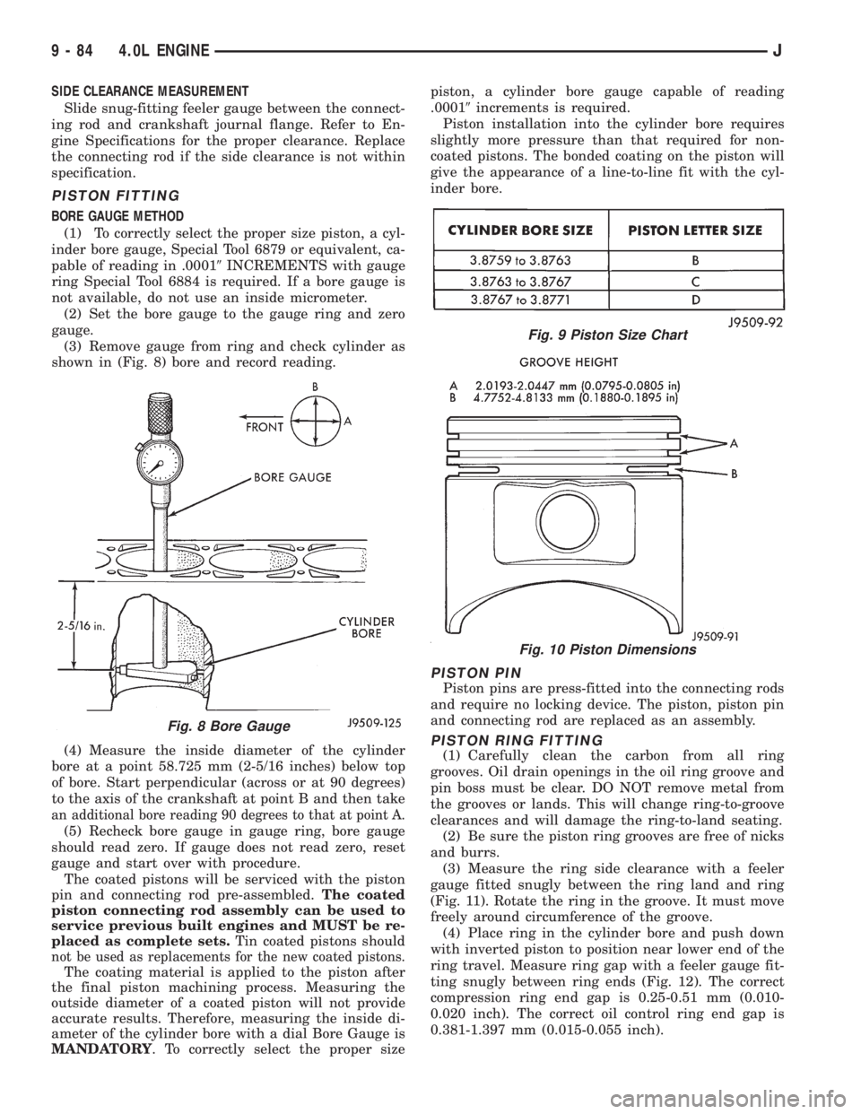
shown in (Fig. 8) bore and record reading.
(4) Measure the inside diameter of the cylinder
bore at a point 58.725 mm (2-5/16 inches) below top
of bore. Start perpendicular (across or at 90 degrees)
to the axis of the crankshaft at point B and then take
an additional bore reading 90 degrees to that at point A.
(5) Recheck bore gauge in gauge ring, bore gauge
should read zero. If gauge does not read zero, reset
gauge and start over with procedure.
The coated pistons will be serviced with the piston
pin and connecting rod pre-assembled.The coated
piston connecting rod assembly can be used to
service previous built engines and MUST be re-
placed as complete sets.Tin coated pistons should
not be used as replacements for the new coated pistons.
The coating material is applied to the piston after
the final piston machining process. Measuring the
outside diameter of a coated piston will not provide
accurate results. Therefore, measuring the inside di-
ameter of the cylinder bore with a dial Bore Gauge is
MANDATORY. To correctly select the proper sizepiston, a cylinder bore gauge capable of reading
.00019increments is required.
Piston installation into the cylinder bore requires
slightly more pressure than that required for non-
coated pistons. The bonded coating on the piston will
give the appearance of a line-to-line fit with the cyl-
inder bore.
PISTON PIN
Piston pins are press-fitted into the connecting rods
and require no locking device. The piston, piston pin
and connecting rod are replaced as an assembly.
PISTON RING FITTING
(1) Carefully clean the carbon from all ring
grooves. Oil drain openings in the oil ring groove and
pin boss must be clear. DO NOT remove metal from
the grooves or lands. This will change ring-to-groove
clearances and will damage the ring-to-land seating.
(2) Be sure the piston ring grooves are free of nicks
and burrs.
(3) Measure the ring side clearance with a feeler
gauge fitted snugly between the ring land and ring
(Fig. 11). Rotate the ring in the groove. It must move
freely around circumference of the groove.
(4) Place ring in the cylinder bore and push down
with inverted piston to position near lower end of the
ring travel. Measure ring gap with a feeler gauge fit-
ting snugly between ring ends (Fig. 12). The correct
compression ring end gap is 0.25-0.51 mm (0.010-
0.020 inch). The correct oil control ring end gap is
0.381-1.397 mm (0.015-0.055 inch).
Fig. 8 Bore Gauge
Fig. 9 Piston Size Chart
Fig. 10 Piston Dimensions
9 - 84 4.0L ENGINEJ
Page 1366 of 2158
(8) Lower the vehicle.
(9) Install the engine cylinder head, push rods,
rocker arms, bridges, pivots and engine cylinder head
cover.
(10) Fill the crankcase with engine oil.
CRANKSHAFT MAIN BEARINGS
REMOVAL
(1) Disconnect negative cable from battery.
(2) Remove the spark plugs.
(3) Raise the vehicle.
(4) Remove the oil pan and oil pump.
(5) Remove only one main bearing cap and lower
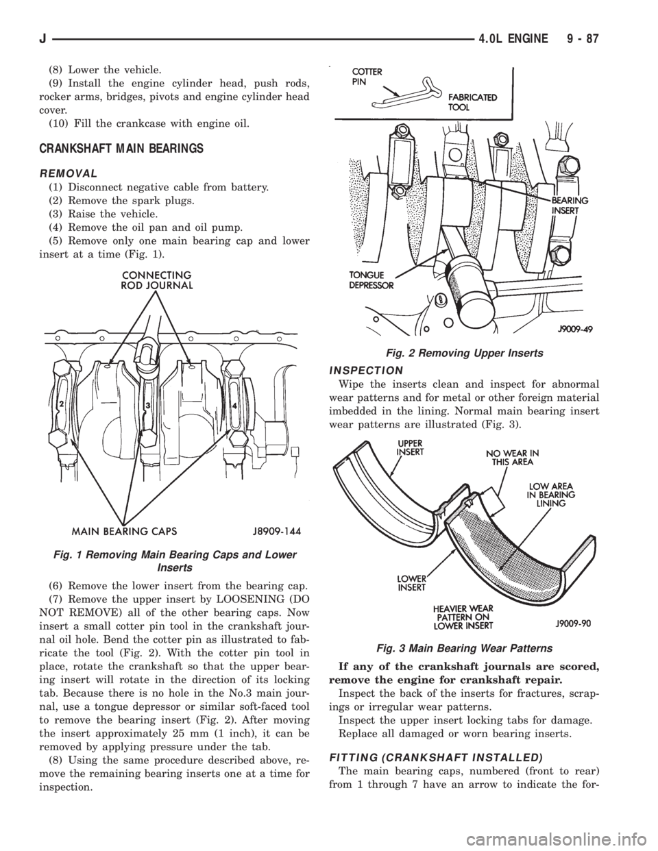
insert at a time (Fig. 1).
(6) Remove the lower insert from the bearing cap.
(7) Remove the upper insert by LOOSENING (DO
NOT REMOVE) all of the other bearing caps. Now
insert a small cotter pin tool in the crankshaft jour-
nal oil hole. Bend the cotter pin as illustrated to fab-
ricate the tool (Fig. 2). With the cotter pin tool in
place, rotate the crankshaft so that the upper bear-
ing insert will rotate in the direction of its locking
tab. Because there is no hole in the No.3 main jour-
nal, use a tongue depressor or similar soft-faced tool
to remove the bearing insert (Fig. 2). After moving
the insert approximately 25 mm (1 inch), it can be
removed by applying pressure under the tab.
(8) Using the same procedure described above, re-
move the remaining bearing inserts one at a time for
inspection.
INSPECTION
Wipe the inserts clean and inspect for abnormal
wear patterns and for metal or other foreign material
imbedded in the lining. Normal main bearing insert
wear patterns are illustrated (Fig. 3).
If any of the crankshaft journals are scored,
remove the engine for crankshaft repair.
Inspect the back of the inserts for fractures, scrap-
ings or irregular wear patterns.
Inspect the upper insert locking tabs for damage.
Replace all damaged or worn bearing inserts.
FITTING (CRANKSHAFT INSTALLED)
The main bearing caps, numbered (front to rear)
from 1 through 7 have an arrow to indicate the for-
Fig. 1 Removing Main Bearing Caps and Lower
Inserts
Fig. 2 Removing Upper Inserts
Fig. 3 Main Bearing Wear Patterns
J4.0L ENGINE 9 - 87
Page 1423 of 2158
²Signal ground
Powertrain Control Module (PCM) Outputs:
²A/C clutch relay
²Idle air control (IAC) motor
²Auto shutdown (ASD) relay
²Generator field
²Malfunction indicator lamp (Check Engine Lamp)
²Fuel injectors
²Fuel pump relay
²Ignition coil
²SCI transmit (DRB scan tool connection)
²Shift indicator lamp (manual transmission only)
²Speed control vacuum solenoid
²Speed control vent solenoid
²Tachometer (on instrument panel, if equipped)
²Torque converter clutch relay (3-speed auto. trans.
only)
The PCM contains a voltage convertor. This con-
verts battery voltage to a regulated 8.0 volts. It is
used to power the crankshaft position sensor, cam-
shaft position sensor and vehicle speed sensor. The
PCM also provides a five (5) volt supply for the Man-
ifold Absolute Pressure (MAP) sensor and Throttle
Position Sensor (TPS).
AIR CONDITIONING (A/C) CONTROLSÐPCM INPUT
The A/C control system information applies to fac-
tory installed air conditioning units only.
A/C SELECT SIGNAL:When the A/C switch is in
the ON position and the A/C low-pressure switch is
closed, an input signal is sent to the powertrain con-
trol module (PCM). The signal informs the PCM that
the A/C has been selected. The PCM adjusts idle
speed to a pre-programmed rpm through the idle air
control (IAC) motor to compensate for increased en-
gine load.
A/C REQUEST SIGNAL:Once A/C has been se-
lected, the PCM receives the A/C request signal from
the evaporator switch. The input indicates that the
evaporator temperature is in the proper range for
A/C application. The PCM uses this input to cycle the
A/C compressor clutch (through the A/C relay). It will
also determine the correct engine idle speed through
the IAC motor position.
If the A/C low-pressure switch opens (indicating a
low refrigerant level), the PCM will not receive an
A/C select signal. The PCM will then remove the
ground from the A/C relay. This will deactivate the
A/C compressor clutch.
If the evaporator switch opens, (indicating that
evaporator is not in proper temperature range), the
PCM will not receive the A/C request signal. The
PCM will then remove the ground from the A/C relay,
deactivating the A/C compressor clutch.
AUTOMATIC SHUTDOWN (ASD) SENSEÐPCM
INPUT
A 12 volt signal at this input indicates to the PCM
that the ASD has been activated. The ASD relay is
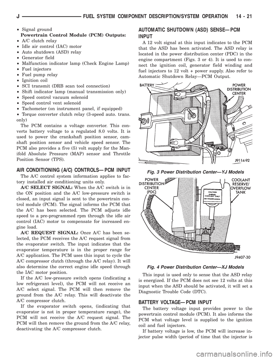
located in the power distribution center (PDC) in the
engine compartment (Figs. 3 or 4). It is used to con-
nect the ignition coil, generator field winding and
fuel injectors to 12 volt + power supply. Also refer to
Automatic Shutdown RelayÐPCM Output.
This input is used only to sense that the ASD relay
is energized. If the PCM does not see 12 volts at this
input when the ASD should be activated, it will set a
Diagnostic Trouble Code (DTC).
BATTERY VOLTAGEÐPCM INPUT
The battery voltage input provides power to the
powertrain control module (PCM). It also informs the
PCM what voltage level is supplied to the ignition
coil and fuel injectors.
If battery voltage is low, the PCM will increase in-
jector pulse width (period of time that the injector is
Fig. 3 Power Distribution CenterÐYJ Models
Fig. 4 Power Distribution CenterÐXJ Models
JFUEL SYSTEM COMPONENT DESCRIPTION/SYSTEM OPERATION 14 - 21
Page 1426 of 2158
The MAP sensor is mounted on the dash panel.
The sensor is connected to the throttle body with a
vacuum hose and to the PCM electrically.
OXYGEN (O2S) SENSORÐPCM INPUT
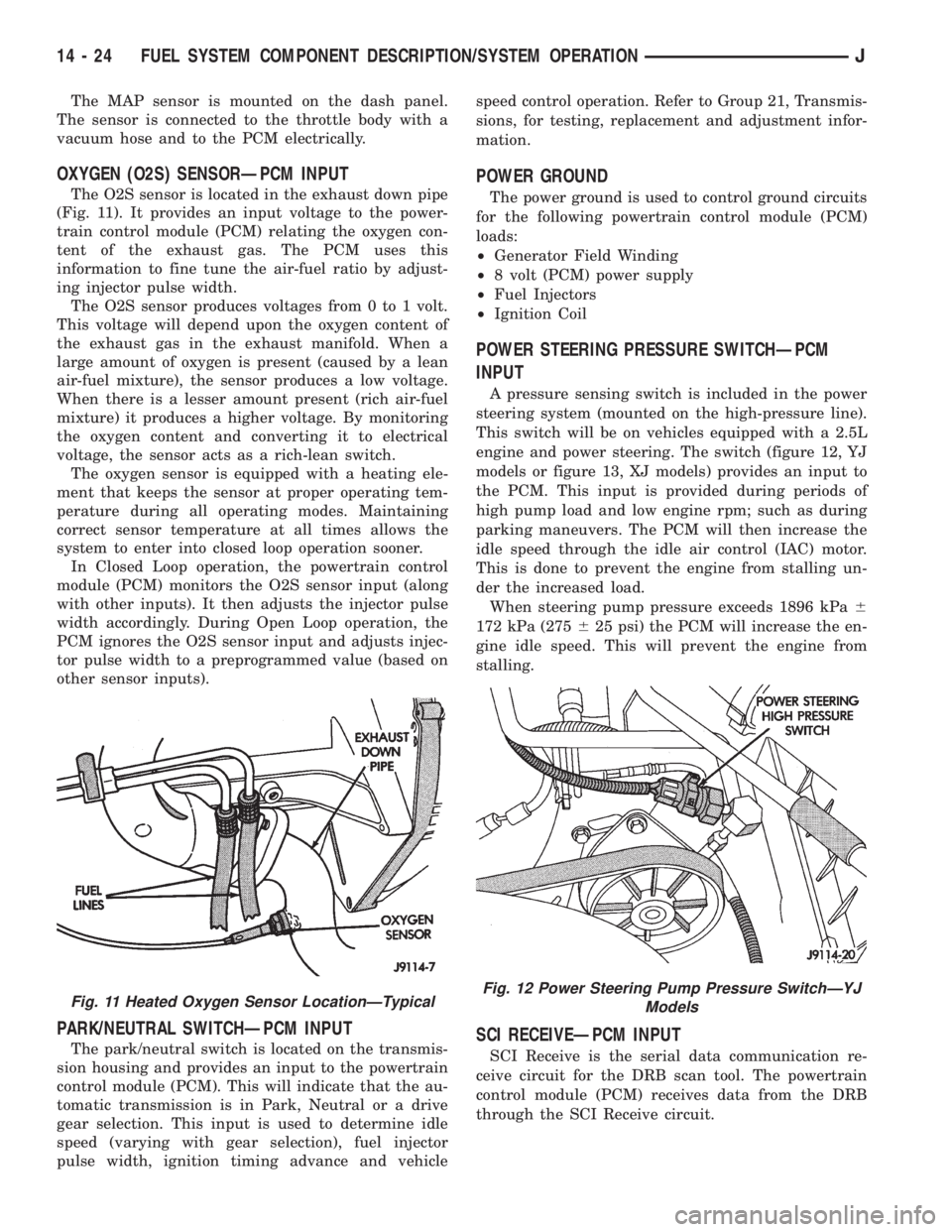
The O2S sensor is located in the exhaust down pipe
(Fig. 11). It provides an input voltage to the power-
train control module (PCM) relating the oxygen con-
tent of the exhaust gas. The PCM uses this
information to fine tune the air-fuel ratio by adjust-
ing injector pulse width.
The O2S sensor produces voltages from 0 to 1 volt.
This voltage will depend upon the oxygen content of
the exhaust gas in the exhaust manifold. When a
large amount of oxygen is present (caused by a lean
air-fuel mixture), the sensor produces a low voltage.
When there is a lesser amount present (rich air-fuel
mixture) it produces a higher voltage. By monitoring
the oxygen content and converting it to electrical
voltage, the sensor acts as a rich-lean switch.
The oxygen sensor is equipped with a heating ele-
ment that keeps the sensor at proper operating tem-
perature during all operating modes. Maintaining
correct sensor temperature at all times allows the
system to enter into closed loop operation sooner.
In Closed Loop operation, the powertrain control
module (PCM) monitors the O2S sensor input (along
with other inputs). It then adjusts the injector pulse
width accordingly. During Open Loop operation, the
PCM ignores the O2S sensor input and adjusts injec-
tor pulse width to a preprogrammed value (based on
other sensor inputs).
PARK/NEUTRAL SWITCHÐPCM INPUT
The park/neutral switch is located on the transmis-
sion housing and provides an input to the powertrain
control module (PCM). This will indicate that the au-
tomatic transmission is in Park, Neutral or a drive
gear selection. This input is used to determine idle
speed (varying with gear selection), fuel injector
pulse width, ignition timing advance and vehiclespeed control operation. Refer to Group 21, Transmis-
sions, for testing, replacement and adjustment infor-
mation.
POWER GROUND
The power ground is used to control ground circuits
for the following powertrain control module (PCM)
loads:
²Generator Field Winding
²8 volt (PCM) power supply
²Fuel Injectors
²Ignition Coil
POWER STEERING PRESSURE SWITCHÐPCM
INPUT
A pressure sensing switch is included in the power
steering system (mounted on the high-pressure line).
This switch will be on vehicles equipped with a 2.5L
engine and power steering. The switch (figure 12, YJ
models or figure 13, XJ models) provides an input to
the PCM. This input is provided during periods of
high pump load and low engine rpm; such as during
parking maneuvers. The PCM will then increase the
idle speed through the idle air control (IAC) motor.
This is done to prevent the engine from stalling un-
der the increased load.
When steering pump pressure exceeds 1896 kPa6
172 kPa (275625 psi) the PCM will increase the en-
gine idle speed. This will prevent the engine from
stalling.
SCI RECEIVEÐPCM INPUT
SCI Receive is the serial data communication re-
ceive circuit for the DRB scan tool. The powertrain
control module (PCM) receives data from the DRB
through the SCI Receive circuit.
Fig. 11 Heated Oxygen Sensor LocationÐTypicalFig. 12 Power Steering Pump Pressure SwitchÐYJ
Models
14 - 24 FUEL SYSTEM COMPONENT DESCRIPTION/SYSTEM OPERATIONJ
Page 1434 of 2158
²The PCM adjusts ignition timing by increasing
and decreasing spark advance.
²The PCM operates the A/C compressor clutch
through the clutch relay. This happens if A/C has
been selected by the vehicle operator and requested
by the A/C thermostat.
The optional Extended Idle Switch is used to raise
the engine idle speed to approximately 1000 rpm.
This is when the shifter is in either the Park or Neu-
tral position. A rocker-type 2-wire switch (extended
idle switch) is mounted to the instrument panel. This
switch will supply a ground circuit to the powertrain
control module (PCM).The switch is available
only with 4.0L engine when supplied with the
optional police package.
CRUISE MODE
When the engine is at operating temperature, this
is a Closed Loop mode. At cruising speed, the power-
train control module (PCM) receives inputs from:
²Air conditioning select signal (if equipped)
²Air conditioning request signal (if equipped)
²Battery voltage
²Engine coolant temperature sensor
²Crankshaft position sensor
²Intake manifold air temperature sensor
²Manifold absolute pressure (MAP) sensor
²Throttle position sensor (TPS)
²Camshaft position sensor signal (in the distribu-
tor)
²Park/neutral switch (gear indicator signalÐauto.
trans. only)
²Oxygen (O2S) sensor
Based on these inputs, the following occurs:
²Voltage is applied to the fuel injectors with the
PCM. The PCM will then adjust the injector pulse
width by turning the ground circuit to each individ-
ual injector on and off.
²The PCM monitors the O2S sensor input and ad-
justs air-fuel ratio. It also adjusts engine idle speed
through the idle air control (IAC) motor.
²The PCM adjusts ignition timing by turning the
ground path to the coil on and off.
²The PCM operates the A/C compressor clutch
through the clutch relay. This happens if A/C has
been selected by the vehicle operator and requested
by the A/C thermostat.
ACCELERATION MODE
This is an Open Loop mode. The powertrain control
module (PCM) recognizes an abrupt increase in
throttle position or MAP pressure as a demand for
increased engine output and vehicle acceleration. The
PCM increases injector pulse width in response to in-
creased throttle opening.
DECELERATION MODE
When the engine is at operating temperature, this
is an Open Loop mode. During hard deceleration, the
powertrain control module (PCM) receives the follow-
ing inputs.
²Air conditioning select signal (if equipped)
²Air conditioning request signal (if equipped)
²Battery voltage
²Engine coolant temperature sensor
²Crankshaft position sensor
²Intake manifold air temperature sensor
²Manifold absolute pressure (MAP) sensor
²Throttle position sensor (TPS)
²Camshaft position sensor signal (in the distribu-
tor)
²Park/neutral switch (gear indicator signalÐauto.
trans. only)
If the vehicle is under hard deceleration with the
proper rpm and closed throttle conditions, the PCM
will ignore the oxygen sensor input signal. The PCM
will enter a fuel cut-off strategy in which it will not
supply battery voltage to the injectors. If a hard de-
celeration does not exist, the PCM will determine the
proper injector pulse width and continue injection.
Based on the above inputs, the PCM will adjust en-
gine idle speed through the idle air control (IAC) mo-
tor.
The PCM adjusts ignition timing by turning the
ground path to the coil on and off.
The PCM opens the ground circuit to the A/C
clutch relay to disengage the A/C compressor clutch.
This is done until the vehicle is no longer under de-
celeration (if the A/C system is operating).
WIDE OPEN THROTTLE MODE
This is an Open Loop mode. During wide open
throttle operation, the powertrain control module
(PCM) receives the following inputs.
²Battery voltage
²Crankshaft position sensor
²Engine coolant temperature sensor
²Intake manifold air temperature sensor
²Manifold absolute pressure (MAP) sensor
²Throttle position sensor (TPS)
²Camshaft position sensor signal (in the distribu-
tor)
During wide open throttle conditions, the following
occurs:
²Voltage is applied to the fuel injectors with the
powertrain control module (PCM). The PCM will
then control the injection sequence and injector pulse
width by turning the ground circuit to each individ-
ual injector on and off. The PCM ignores the oxygen
sensor input signal and provides a predetermined
amount of additional fuel. This is done by adjusting
injector pulse width.
²The PCM adjusts ignition timing by turning the
ground path to the coil on and off.
14 - 32 FUEL SYSTEM COMPONENT DESCRIPTION/SYSTEM OPERATIONJ
Page 1437 of 2158
MULTI-PORT FUEL INJECTION (MFI)ÐGENERAL DIAGNOSIS
INDEX
page page
Automatic Shutdown (ASD) Relay Testing....... 46
Camshaft Position Sensor Test............... 46
Crankshaft Position Sensor Test.............. 47
Diagnostic Trouble Code (DTC)............... 54
DRB Scan Tool........................... 54
Engine Coolant Temperature Sensor Test....... 46
Extended Idle Switch Test................... 48
Fuel Injector Test......................... 51
Fuel Pump Relay Testing................... 47
Fuel System Pressure Test.................. 51
General Information....................... 35
Idle Air Control Motor Test................... 49
Intake Manifold Air Temperature Sensor Test..... 46Manifold Absolute Pressure (Map) Sensor Test . . . 47
On-Board Diagnostics (OBD)................. 51
Oxygen Sensor (O2S) Heating Element Test..... 48
Pcm System Schematics.................... 41
Powertrain Control Module (PCM) 60-Way
Connector............................. 40
RelaysÐOperation/Testing.................. 50
Starter Motor Relay Test.................... 51
Throttle Position Sensor (TPS) Test............ 48
Torque Converter Clutch Relay Test............ 48
Vehicle Speed Sensor Test.................. 48
Visual Inspection.......................... 35
GENERAL INFORMATION
All 2.5L 4-cylinder and 4.0L 6-cylinder engines are
equipped with sequential Multi-Port Fuel Injection
(MFI). The MFI system provides precise air/fuel ra-
tios for all driving conditions.
VISUAL INSPECTION
A visual inspection for loose, disconnected, or incor-
rectly routed wires and hoses should be made. This
should be done before attempting to diagnose or ser-
vice the fuel injection system. A visual check will
help spot these faults and save unnecessary test and
diagnostic time. A thorough visual inspection will in-
clude the following checks:
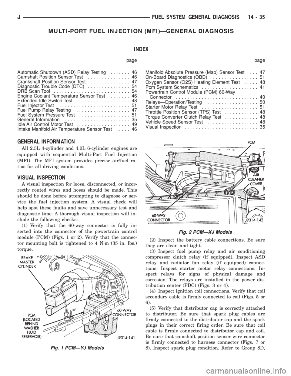
(1) Verify that the 60-way connector is fully in-
serted into the connector of the powertrain control
module (PCM) (Figs. 1 or 2). Verify that the connec-
tor mounting bolt is tightened to 4 Nzm (35 in. lbs.)
torque.(2) Inspect the battery cable connections. Be sure
they are clean and tight.
(3) Inspect fuel pump relay and air conditioning
compressor clutch relay (if equipped). Inspect ASD
relay and radiator fan relay (if equipped) connec-
tions. Inspect starter motor relay connections. In-
spect relays for signs of physical damage and
corrosion. The relays are installed in the power dis-
tribution center (PDC) (Figs. 3 or 4).
(4) Inspect ignition coil connections. Verify that coil
secondary cable is firmly connected to coil (Figs. 5 or
6).
(5) Verify that distributor cap is correctly attached
to distributor. Be sure that spark plug cables are
firmly connected to the distributor cap and the spark
plugs in their correct firing order. Be sure that coil
cable is firmly connected to distributor cap and coil.
Be sure that camshaft position sensor wire connector
is firmly connected to harness connector (Figs. 7 or
8). Inspect spark plug condition. Refer to Group 8D,
Fig. 1 PCMÐYJ Models
Fig. 2 PCMÐXJ Models
JFUEL SYSTEM GENERAL DIAGNOSIS 14 - 35
Page 1453 of 2158
(8) Disconnect jumper wires from relay and 12 Volt
power source.
If continuity or resistance tests did not pass, re-
place relay. If tests passed, refer to Group 8W, Wiring
Diagrams for additional circuit information. Also re-
fer to the appropriate Powertrain Diagnostic Proce-
dures manual for operation of the DRB scan tool.
STARTER MOTOR RELAY TEST
Refer to Group 8A, Battery/Starting/Charging/Sys-
tem Diagnostics, for starter motor relay testing.
FUEL INJECTOR TEST
To perform a complete test of the fuel injectors and
their circuitry, refer to DRB scan tool and appropri-
ate Powertrain Diagnostics Procedures manual. To
test the injector only, refer to the following:
Disconnect the injector wire connector from the in-
jector. Place an ohmmeter on the injector terminals.
Resistance reading should be approximately 14.5
ohms61.2 ohms at 20ÉC (68ÉF). Proceed to the fol-
lowing Injector Diagnosis chart.When performing
the following tests from the chart, do not leave
electrical current applied to the injector for
longer than five seconds. Damage to injector
coil or internal injector seals could result.
FUEL SYSTEM PRESSURE TEST
Refer to the Fuel Delivery System section of this
group. See Fuel System Pressure Test.
ON-BOARD DIAGNOSTICS (OBD)
The powertrain control module (PCM) has been
programmed to monitor many different circuits of the
fuel injection system. If a problem is sensed in a
monitored circuit often enough to indicate an actual
problem, a Diagnostic Trouble Code (DTC) is stored.
The DTC will be stored in the PCM memory for even-
tual display to the service technician. If the problem
is repaired or ceases to exist, the PCM cancels the
DTC after 51 engine starts.Certain criteria must be met for a diagnostic trou-
ble code (DTC) to be entered into PCM memory. The
criteria may be a specific range of engine rpm, engine
temperature and/or input voltage to the PCM.
It is possible that a DTC for a monitored circuit
may not be entered into memory even though a mal-
function has occurred. This may happen because one
of the DTC criteria for the circuit has not been met.
Example: assume that one of the criteria for the
MAP sensor circuit is that the engine must be oper-
ating between 750 and 2000 rpm to be monitored for
a DTC. If the MAP sensor output circuit shorts to
ground when the engine rpm is above 2400 rpm, a 0
volt input will be seen by the PCM. A DTC will not
be entered into memory because the condition does
not occur within the specified rpm range.
A DTC indicates that the powertrain control mod-
ule (PCM) has recognized an abnormal signal in a
circuit or the system. A DTC may indicate the result
of a failure, but never identify the failed component
directly.
There are several operating conditions that the
PCM does not monitor and set a DTC for. Refer to
the following Monitored Circuits and Non-Monitored
Circuits in this section.
MONITORED CIRCUITS
The powertrain control module (PCM) can detect
certain problems in the fuel injection system.
Open or Shorted Circuit- The PCM can deter-
mine if sensor output (which is the input to PCM) is
within proper range. It also determines if the circuit
is open or shorted.
Output Device Current Flow- The PCM senses
whether the output devices are hooked up.
If there is a problem with the circuit, the PCM
senses whether the circuit is open, shorted to ground
(-), or shorted to (+) voltage.
Oxygen Sensor- The PCM can determine if the
oxygen sensor is switching between rich and lean.
This is, once the system has entered Closed Loop. Re-
fer to Open Loop/Closed Loop Modes Of Operation in
the Component Description/System Operation section
for an explanation of Closed (or Open) Loop opera-
tion.
NON-MONITORED CIRCUITS
The PCM does not monitor the following circuits,
systems or conditions that could have malfunctions
that result in driveability problems. A Diagnostic
Trouble Code (DTC) may not be displayed for these
conditions.
Fuel Pressure:Fuel pressure is controlled by the
vacuum assisted fuel pressure regulator. The PCM
cannot detect a clogged fuel pump inlet filter, clogged
in-line fuel filter, or a pinched fuel supply or return
Fig. 44 Fuel Injector Internal ComponentsÐTypical
JFUEL SYSTEM GENERAL DIAGNOSIS 14 - 51
Page 1485 of 2158
STEERING
CONTENTS
page page
GENERAL INFORMATION.................. 1
GENERAL INFORMATION................. 48
MANUAL STEERING GEAR................ 37
POWER STEERING PUMP................. 11
POWER STEERING SYSTEM DIAGNOSIS...... 3
RECIRCULATING BALL POWER STEERING
GEAR............................... 21STEERING COLUMN GENERAL SERVICEÐXJ . 47
STEERING COLUMNÐYJ................. 58
STEERING LINKAGEÐXJ................. 16
STEERING LINKAGEÐYJ................. 19
STEERING RHD......................... 74
TORQUE SPECIFICATIONS................ 78
GENERAL INFORMATION
STEERING SYSTEM COMPONENTS
Jeep vehicles can have either a manual or power
steering system (Fig. 1). A recirculating-ball type
steering gear is used for both systems.
Power steering systems use;
²Steering gear
²Pressure and return fluid hoses and fittings
²Belt driven steering pump
²Integral or remote body mounted pump reservoir
POWER STEERING GEAR
The steering gear is mounted on the left frame rail.
The gear is joined to the intermediate shaft by a uni-
versal joint coupling. The coupling helps isolate noise
and road shock from the interior.
The major internal components of the gear are the:
²Rotary valve assembly
²Steering worm shaft
²Rack piston assembly
²Pitman shaftThe movement of these parts, while turning or
parking, is aided by hydraulic pressure and flow sup-
plied by the pump. Manual steering is always avail-
able at times when the engine is not running or in
the event of pump or belt failure. Steering effort is
higher under such conditions.
The steering stub shaft, rotary valve, worm shaft,
and rack piston assembly are all in line. The oil pas-
sages are internal within the gear housing except for
pressure and return hoses between the gear and
pump.
The power steering gear has a recirculating ball
system. This acts as a rolling thread between the
worm shaft and rack piston. The worm shaft is sup-
ported by a thrust bearing at the lower end and a
bearing assembly at the upper end. When the worm
shaft is turned right, the rack piston moves up in
gear. Turning the worm shaft left moves the rack pis-
ton down in gear. The rack piston teeth mesh with
the sector, which is part of the pitman shaft. Turning
the worm shaft turns the pitman shaft, which turns
the wheels through the steering linkage.
The control valve in the steering gear directs the
power steering fluid to either side of the rack piston.
The rack piston is assisted by hydraulic pressure. If
the steering system loses hydraulic pressure, the ve-
hicle can be controlled manually, but with higher
steering effort.
An identification code located on the side cover des-
ignates the gear ratio (Fig. 2).
²Code BH designates 14:1 ratio used in XJ vehicles
²Code BF designates 13-16:1 ratio used in YJ vehi-
cles
A recirculating-ball steering gear is used with the
power (assisted) steering system (Fig. 1). The power
steering gear can be adjusted and internally serviced.
Fig. 1 Steering Gears
JSTEERING 19 - 1