1995 JEEP YJ engine oil capacity
[x] Cancel search: engine oil capacityPage 22 of 2158

FLUID CAPACITIES
Fuel Tank
XJ .....................................................76.4 L (20.2 gal.)
YJ(Standard) ......................................56.8 L (15 gal.)
YJ(Optional) .......................................75.7 L (20 gal.)
Engine Oil
2.5L ......................................................3.8 L (4.0 qts.)
4.0L ......................................................5.7 L (6.0 qts.)
Cooling System
2.5L(XJ).............................................9.5 L* (10 qts.*)
2.5L(YJ) ........................................8.5 L** (9.0 qts.**)
4.0L(XJ) ........................................11.4 L* (12.0 qts.*)
4.0L(YJ) ......................................9.9 L** (10.5 qts.**)
* Includes (2.2 L) (2.3 qts) for coolant recovery res-
ervoir.
** Includes (0.9 L) (1.0 qt.) for coolant recovery res-
ervoir.
Automatic Transmission
Dry fill capacity.*
AW4 (XJ-4.0L) ...................................8.0 L (16.9 pts.)
30RH (YJ-2.5L) .................................8.2 L (17.5 pts.)
32RH (YJ-4.0L) .................................8.2 L (17.5 pts.)
*Depending on type and size of internal cooler,
length and inside diameter of cooler lines, or use ofan auxiliary cooler, these figures may vary. Refer to
Group 21, Transmission for proper fluid fill proce-
dure.
Manual Transmission
AX4/5 (4X2) .........................................3.3 L (3.5 qts.)
AX5 (4X4) ............................................3.2 L (3.3 qts.)
AX15 (4X2) ..........................................3.1 L (3.2 qts.)
AX15 (4X4) ......................................3.15 L (3.32 qts.)
Fill to bottom of fill hole.
Transfer Case
SELEC-TRAC 242(XJ) .......................1.4 L (3.0 pts.)
COMMAND-TRAC 231(XJ) ...............1.0 L (2.2 pts.)
COMMAND-TRAC 231(YJ-Man Trans) ..1.5 L (3.25
pts.)
COMMAND-TRAC 231(YJ-Auto Trans) ....1.0 L (2.2
pts.)
Front Axle
MODEL 30 (YJ) ..............................1.65 L (3.76 pts.)
MODEL 30 (XJ) ..............................1.48 L (3.13 pts.)
Rear Axle
MODEL 35 (XJ-YJ) ........................1.6 L (3.38 pts.*)
8-1/4 (XJ) .........................................2.08 L (4.4 pts.*)
* When equipped with TRAC-LOK, include 2
ounces of Friction Modifier Additive.
JLUBRICATION AND MAINTENANCE 0 - 3
Page 37 of 2158

USED ENGINE OIL DISPOSAL
Care should be exercised when disposing used en-
gine oil after it has been drained from a vehicle en-
gine. Refer to the WARNING listed above.
ENGINE COOLING SYSTEM
WARNINGS AND PRECAUTIONS
WARNING: ANTIFREEZE IS AN ETHYLENE GLYCOL
BASE COOLANT AND IS HARMFUL IF SWAL-
LOWED OR INHALED. IF SWALLOWED, DRINK
TWO GLASSES OF WATER AND INDUCE VOMIT-
ING. IF INHALED, MOVE TO FRESH AIR AREA.
SEEK MEDICAL ATTENTION IMMEDIATELY. DO NOT
STORE IN OPEN OR UNMARKED CONTAINERS.
WASH SKIN AND CLOTHING THOROUGHLY AFTER
COMING IN CONTACT WITH ETHYLENE GLYCOL.
KEEP OUT OF REACH OF CHILDREN.
DISPOSE OF GLYCOL BASE COOLANT PROP-
ERLY, CONTACT YOUR DEALER OR GOVERNMENT
AGENCY FOR LOCATION OF COLLECTION CENTER
IN YOUR AREA.
DO NOT OPEN A COOLING SYSTEM WHEN THE
ENGINE IS AT RUNNING TEMPERATURE, PER-
SONAL INJURY CAN RESULT.
AVOID RADIATOR COOLING FAN WHEN ENGINE
COMPARTMENT RELATED SERVICE IS PER-
FORMED, PERSONAL INJURY CAN RESULT.
CAUTION: Do not use straight antifreeze as engine
coolant, inadequate engine running temperatures
can result.
Do not operate vehicle without proper concentra-
tion of recommended ethylene glycol coolant, high
running temperatures and cooling system corrosion
can result.
The engine cooling system will develop internal
pressure of 97 to 123 kPa (14 to 18 psi) at normal op-
erating temperature. Allow the vehicle approximately
one half hour to cool off before opening the cooling
system. As an indicator of pressure, squeeze the up-
per radiator hose between index finger and thumb. If
it collapses with little effort the system would have
low internal pressure and should be safe to open to
the first safety notch of the radiator cap. Refer to
Group 7, Cooling System.
COOLING SYSTEM INSPECTION
Coolant level should be inspected when other en-
gine compartment service is performed or when cool-
ant leak is suspected. With the engine at normal
operating temperature, observe the coolant level in
thecoolant recovery bottle. The coolant level mustbe at least above the ADD mark and preferably at
the FULL mark. Add coolant to the coolant recovery
bottleonly, if necessary.
Cooling system freeze protection should be tested
at the onset of the winter season or every 12 months.
Service is required if coolant is low, contaminated,
rusty or freeze protection is inadequate. To properly
test cooling system, see Group 7, Cooling System.
The cooling system factory fill is a mixture of 50%
Ethylene Glycol based antifreeze and 50% water. Us-
ing a suitable hydrometer, measure antifreeze con-
centration in the radiator when the engine is cool. If
the cooling system has recently been serviced, allow
coolant to circulate for at least 20 minutes before
taking hydrometer reading. Properly mixed coolant
will protect the cooling system to -37ÉC (-35ÉF). If the
freeze protection is above -28ÉC (-20ÉF), drain enough
coolant from the cooling system to allow room to add
antifreeze to achieve adequate protection. A mix table
on the coolant container indicates the amount of an-
tifreeze required to winterize the cooling system
based on the capacity, see Capacity Chart in General
Information section of this group.
ANTIFREEZE SPECIFICATION
Chrysler Corporation recommends the use of Mo-
par Antifreeze/Coolant or a high quality, ethylene
glycol base antifreeze/coolant, with a silicate inhibi-
tor.
COOLING SYSTEM SERVICE
The cooling system should be drained, flushed and
filled with the proper coolant mixture at the inter-
vals described in the Lubrication and Maintenance
Schedules. Refer to General Information section of
this group. For proper service instructions see Group
7, Cooling System.
AIR CLEANER ELEMENT
The air cleaner element should be serviced at the
intervals described in the Lubrication and Mainte-
nance Schedules sections of this group. Additional in-
formation can be found in Group 14, Fuel System
and Group 25, Emission System. Inspect all air
cleaner hoses or tubes for damage or leaks when
other engine compartment service is performed. Re-
place faulty components.
FILTER ELEMENT SERVICE/REPLACEMENT
CAUTION: The air cleaner cover must be installed
properly for the emissions system and engine con-
troller to function correctly.
Do not immerse paper air filter element in clean-
ing solvents, damage can result.
(1) Remove the air cleaner cover from the body/
housing (Fig. 9).
0 - 18 LUBRICATION AND MAINTENANCEJ
Page 1727 of 2158
AW-4 AUTOMATIC TRANSMISSION
CONTENTS
page page
AW-4 AUTOMATIC TRANSMISSION........ 165
AW-4 IN-VEHICLE SERVICE.............. 182
AW-4 TRANSMISSION DIAGNOSIS......... 176
AW-4 TRANSMISSION OVERHAUL......... 201AW-4 TRANSMISSION REMOVAL AND
INSTALLATION....................... 198
GENERAL INFORMATION................ 165
GENERAL INFORMATION
INDEX
page page
Components and Operation................. 166
Description............................. 165
First/Second/Third/Reverse Components....... 168
Fourth Gear Overdrive Components.......... 167
Geartrain Operation and Application Charts..... 169Hydraulic System........................ 169
Recommended Fluid and Capacity........... 166
Torque Converter........................ 167
Transmission Identification.................. 166
Transmission Ranges and Shift Lever Positions . . 166
DESCRIPTION
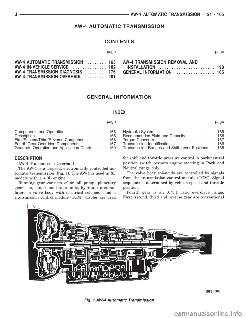
AW-4 Transmission Overhaul
The AW-4 is a 4-speed, electronically controlled au-
tomatic transmission (Fig. 1). The AW-4 is used in XJ
models with a 4.0L engine.
Running gear consists of an oil pump, planetary
gear sets, clutch and brake units, hydraulic accumu-
lators, a valve body with electrical solenoids and a
transmission control module (TCM). Cables are usedfor shift and throttle pressure control. A park/neutral
position switch permits engine starting in Park and
Neutral range only.
The valve body solenoids are controlled by signals
from the transmission control module (TCM). Signal
sequence is determined by vehicle speed and throttle
position.
Fourth gear is an 0.75:1 ratio overdrive range.
First, second, third and reverse gear are conventional
Fig. 1 AW-4 Automatic Transmission
JAW-4 AUTOMATIC TRANSMISSION 21 - 165
Page 2090 of 2158
oil until you are ready to use it. Install the cap im-
mediately after using. Store the oil only in a clean
moisture-free container.
Keep service tools and the work area clean. Con-
tamination of A/C system through careless work hab-
its must be avoided.
COOLING SYSTEM
To maintain the performance level of the heating/
air conditioning system, the engine cooling system
must be properly maintained.
The use of a bug screen is not recommended. Any
obstructions in front of the radiator or condenser can
reduce the performance of the A/C and cooling sys-
tem. If a bug screen is used it must be cleaned fre-
quently.
COOLANT PRECAUTIONS
WARNING: ANTIFREEZE IS AN ETHYLENE GLYCOL
BASE COOLANT AND IS HARMFUL IF SWAL-
LOWED OR INHALED. IF SWALLOWED, DRINK
TWO GLASSES OF WATER AND INDUCE VOMIT-
ING. IF INHALED, MOVE TO FRESH AIR AREA.
SEEK MEDICAL ATTENTION IMMEDIATELY.
WARNING: WASH SKIN AND CLOTHING THOR-
OUGHLY AFTER COMING IN CONTACT WITH ETH-
YLENE GLYCOL.
WARNING: KEEP OUT OF REACH OF CHILDREN
AND PETS.
WARNING: DO NOT OPEN A COOLING SYSTEM
WHEN THE ENGINE IS AT RUNNING TEMPERA-
TURE. PERSONAL INJURY CAN RESULT.WARNING: DO NOT STORE IN OPEN OR UN-
MARKED CONTAINERS.
WARNING: HOT ENGINE COOLANT CAN CAUSE
SEVERE BURNS. DO NOT OPEN THE RADIATOR
DRAIN COCK WHEN THE COOLING SYSTEM IS
HOT AND PRESSURIZED. ALLOW THE COOLANT
TO DECREASE TO ROOM TEMPERATURE BEFORE
STARTING REPAIR OPERATIONS.
The engine cooling system is designed to develop
internal pressure of 97 to 124 kPa (14 to 18 psi). Al-
low the vehicle 15 minutes to cool down (or until a
safe temperature and pressure are attained) before
opening the cooling system. Refer to Group 7, Cooling
System.REFRIGERANT HOSES/TUBES PRECAUTIONS
Kinks or sharp bends in the refrigerant tubing or
hoses will reduce the capacity of the entire system.
High pressures are produced in the system when it is
operating. Extreme care must be exercised to make
sure that all connections are pressure tight. Dirt and
moisture can enter the system when it is opened for
repair.
A good rule for the flexible hose lines is to keep the
radius of all bends at least 10 times the diameter of
the hose. Sharp bends will reduce the flow of refrig-
erant. The flexible hose lines should be routed so
they are at least 80 mm (3 inches) from the exhaust
manifold. It is a good practice to inspect all flexible
hose lines at least once a year to make sure they are
in good condition and properly routed.
24 - 10 HEATING AND AIR CONDITIONINGJ
Page 2091 of 2158
REFRIGERANT SERVICE AND PERFORMANCE TEST
INDEX
page page
Air Conditioning Performance Tests............ 12
Charging Refrigerant System................. 11
Evacuating Refrigerant System............... 11Leak Testing Refrigerant.................... 11
Recovering Refrigerant System............... 11
Refrigerant Oil........................... 12
LEAK TESTING REFRIGERANT
REVIEW WARNINGS AND CAUTIONS IN
THIS GROUP BEFORE LEAK TESTING.
If A/C system is not cooling properly, determine if
system is fully charged. Refer to Refrigerant System
Diagnosis Chart. If the system is empty evacuate the
A/C system and charge system with 0.283 kPa (0.6
lbs. or 10 oz.) R-134a refrigerant. Refer to Charging
Refrigerant System for instructions. To detect a leak
in the system, perform the following procedures.
(1) Position the vehicle in a wind free work area.
This will aid in detecting small leaks.
(2) Bring A/C system up to operating temperature
and pressure. This is done by allowing the engine to
run with the A/C on for 5 to 7 minutes.
(3) Open hood 5 minutes prior to leak test. This
will dissipate any accumulated refrigerant in the en-
gine compartment.
(4) With the engine not running, use an R-134a
Electronic Leak Detector and search for leaks. Move
probe slowly along the bottom side of lines and fit-
tings, because R-134a is heavier than air. Fittings,
lines, or components that appear to be oily usually
indicates a refrigerant leak.
(5) To inspect the evaporator core for leaks. Set the
blower at low speed and the selector in PANEL and
RECIRC mode check for leaks at CENTER panel out-
lets.
RECOVERING REFRIGERANT SYSTEM
REVIEW WARNINGS AND CAUTIONS IN
GENERAL INFORMATION SECTION OF THIS
GROUP BEFORE DISCHARGING SYSTEM.
R-134a refrigerant is a hydrofluorocarbon (HFC)
that does not contain chlorine. R-134a refrigerant Re-
covery/Recycling Station that meets SAE standard
J2210 must be used to recover the refrigerant. Refer
to the operating instructions provided with the equip-
ment for proper operation.
EVACUATING REFRIGERANT SYSTEM
REVIEW WARNINGS AND CAUTIONS IN
GENERAL INFORMATION SECTION OF THIS
GROUP BEFORE EVACUATING SYSTEM.
If the A/C system has been open to the atmosphere,
it must be evacuated before the system can be
charged. Moisture and air mixed with refrigerant will
raise the compressor head pressure above acceptable
operating levels. This will reduce the performance of
the air conditioner and damage the compressor. Mois-
ture will boil at near room temperature when ex-
posed to vacuum. To evacuate the refrigerant system
use following procedure:
(1) Connect a suitable charging station and mani-
fold gauge set to the vehicle.
(2) Open the low and high side valves and start
vacuum pump. When suction gauge reads 88 kPa (26
in. Hg) vacuum or greater, close all valves and turn
off vacuum pump. If system fails to reach specified
vacuum, the system has a leak that must be cor-
rected. If system maintains the specified vacuum for
30 minutes, start the vacuum pump. Then open the
suction and discharge valves and evacuate an addi-
tional 10 minutes.
(3) Close all valves. Turn off and disconnect the
vacuum pump.
The system is now ready to be charged with refrig-
erant.
CHARGING REFRIGERANT SYSTEM
REVIEW WARNINGS AND CAUTIONS IN
GENERAL INFORMATION SECTION OF THIS
GROUP BEFORE CHARGING SYSTEM.
After the system has been tested for leaks and
evacuated, a refrigerant charge can be injected into
the system. Refer to refrigerant capacities for proper
amount of refrigerant charge. Charge the system us-
ing a Recovery/Recycling/Charging Station approved
for R-134a refrigerant. Refer to the instructions pro-
vided with the equipment for proper operation.
REFRIGERANT CHARGE CAPACITY
The R-134a system charge capacity is 0.9 kPa (32
oz.) for XJ and YJ vehicles.
JHEATING AND AIR CONDITIONING 24 - 11
Page 2092 of 2158
REFRIGERANT OIL
It is important to have the correct amount of oil in
the A/C system. This will ensure proper lubrication of
the compressor. Too little oil will result in damage to
the compressor. Too much oil will reduce the cooling
capacity of the system.
The oil used in the SD7H15 compressor is a poly-
alkylene glycol synthetic oil SP-20 PAG, wax-free re-
frigerant oil. Only refrigerant oil of the same type
should be used to service the system. Do not use any
other oil. The oil container should be kept tightly
capped until it is ready for use and then capped after
use to prevent contamination. Refrigerant oil will
quickly absorb any moisture it comes in contact with.
OIL LEVEL CHECK
It will not be necessary to check oil level in the
compressor or to add oil unless there has been an oil
loss. This may be due to a rupture or leak from a
line, shaft seal, evaporator or condenser. Oil loss at a
leak point will be evident by the presence of a wet,
shiny surface around the leak.
When an A/C system is assembled at the factory,
all components (except the compressor) are refriger-
ant oil free. After the system has been charged and
operated, the oil in the compressor is dispersed
through the system. The receiver-drier, evaporator,
condenser and compressor will retain a significant
amount of oil.
Refrigerant oil must be added when a receiver-
drier, evaporator, condenser or compressor are re-
placed. When the compressor is replaced, the oil
must be drained from the replaced compressor and
measured. Drain all the oil from the new compressor.
Add back into the new compressor the amount of oil
that was drained out of the old compressor.
Add an additional 30 ml (1 fluid oz.) of com-
pressor oil to the system when a receiver-drier,
condenser or evaporator is replaced.
AIR CONDITIONING PERFORMANCE TESTS
Humidity has an important bearing on the temper-
ature of the air delivered to the vehicle's interior. It
is important to understand the effect humidity has
on the performance of the system. When humidity is
high, the evaporator has to perform a double duty. It
must lower the air temperature and the temperature
of the moisture carried in the air. Condensing the
moisture in the air transfers a great deal of heat en-
ergy into the evaporator fins and tubing. This re-
duces the amount of heat the evaporator can absorb
from the air. High humidity greatly reduces the evap-
orator's ability to lower the temperature of the air.Evaporator capacity used to reduce the amount of
moisture in the air is not wasted. Wringing some of
the moisture out of the air entering the vehicle adds
to the comfort of the passengers. However, an owner
may expect too much from their air conditioning sys-
tem on humid days. A performance test is the best
way to determine whether or not the system is per-
forming up to standard. This test also provides valu-
able clues to the possible cause of trouble.
Air temperature in test room must be 21ÉC (70ÉF)
minimum for this test.
(1) Connect a Tachometer and manifold gauge set.
(2) Set A/C controls to Max A/C, temperature lever
on full cool and blower on high.
(3) Start engine and adjust idle to 1,000 RPM with
A/C clutch engaged.
(4) Engine should be warmed up with doors, win-
dows and hood closed.
(5) Insert a thermometer in the left center A/C out-
let. Operate the A/C and engine for 5 minutes. The
A/C clutch may cycle depending on ambient temper-
atures.
(6) After 5 minutes note the discharge air temper-
ature. If the clutch cycles, take the reading before
the clutch disengages.
(7) On LHD XJ vehicles open the hood and discon-
nect vacuum line going to the heater water control
valve. Observe the valve arm for movement as the
line is disconnected. Plug the vacuum line to prevent
leakage. If it does not move repair vacuum circuit.
(8) Operate the A/C for 2 more minutes and take
the discharge air temperature reading again. On XJ
vehicles if the temperature increased by more than
2ÉC (5ÉF) check the blend air door cable for correct
operation.
(9) Compare the discharge air temperature to the
A/C Performance (Temperature and Pressure) Chart.
If the discharge air temperature is high, refer to Re-
frigerant Leak Testing and Refrigerant System Diag-
nosis Chart.
(10) Compare the compressor discharge and suc-
tion pressures to the A/C Performance (Temperature
and Pressure) Chart. If the compressor discharge or
suction pressure is not normal, check the operation of
the refrigerant system. Refer to Refrigerant System
Diagnosis Chart.
If pressures are abnormal, refer to the Pressure
and Performance Diagnosis Charts.
The following chart have been developed for quick
reference.
24 - 12 HEATING AND AIR CONDITIONINGJ
Page 2128 of 2158
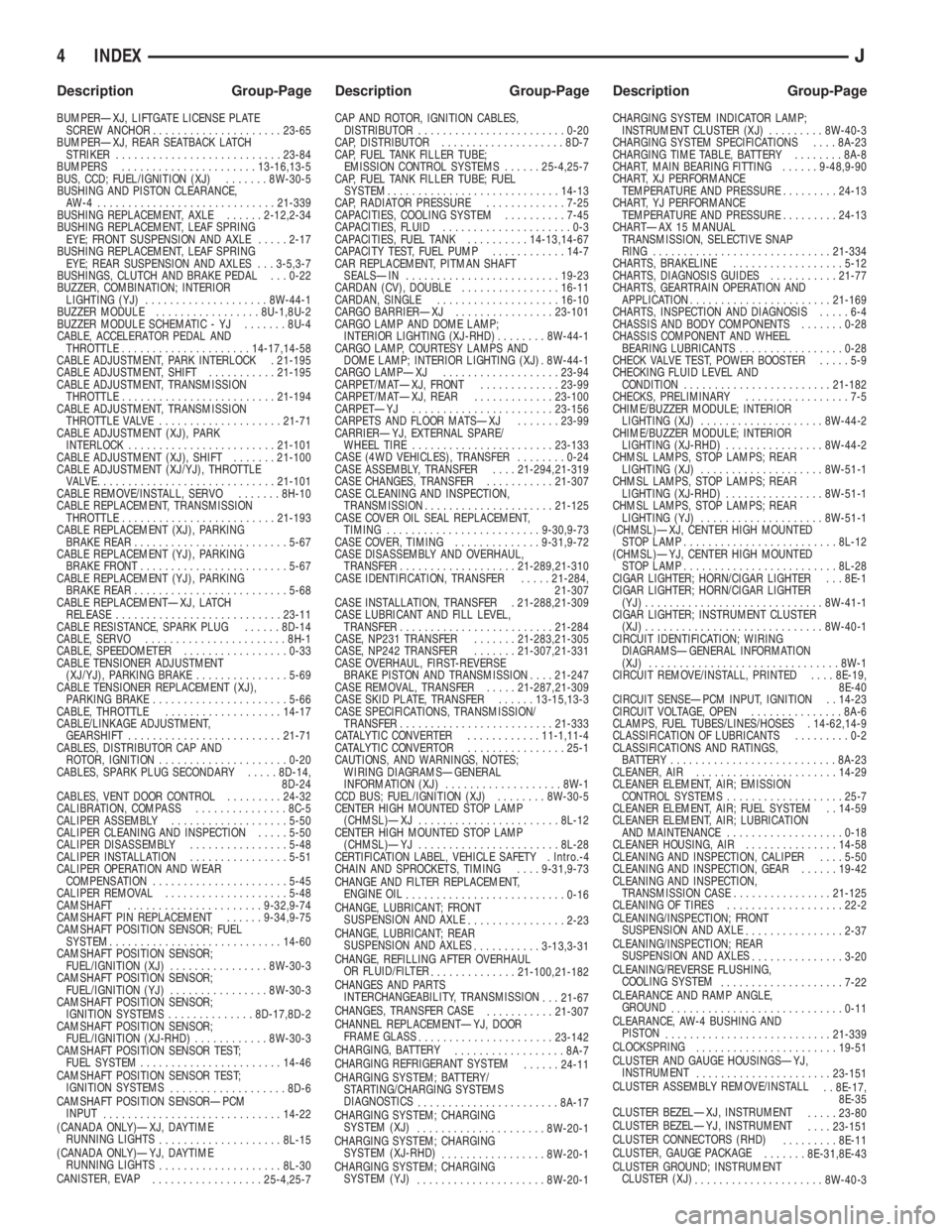
BUMPERÐXJ, LIFTGATE LICENSE PLATE
SCREW ANCHOR.....................23-65
BUMPERÐXJ, REAR SEATBACK LATCH
STRIKER...........................23-84
BUMPERS......................13-16,13-5
BUS, CCD; FUEL/IGNITION (XJ).......8W-30-5
BUSHING AND PISTON CLEARANCE,
AW-4 .............................21-339
BUSHING REPLACEMENT, AXLE......2-12,2-34
BUSHING REPLACEMENT, LEAF SPRING
EYE; FRONT SUSPENSION AND AXLE.....2-17
BUSHING REPLACEMENT, LEAF SPRING
EYE; REAR SUSPENSION AND AXLES . . . 3-5,3-7
BUSHINGS, CLUTCH AND BRAKE PEDAL . . . 0-22
BUZZER, COMBINATION; INTERIOR
LIGHTING (YJ)....................8W-44-1
BUZZER MODULE.................8U-1,8U-2
BUZZER MODULE SCHEMATIC - YJ.......8U-4
CABLE, ACCELERATOR PEDAL AND
THROTTLE.....................14-17,14-58
CABLE ADJUSTMENT, PARK INTERLOCK . 21-195
CABLE ADJUSTMENT, SHIFT...........21-195
CABLE ADJUSTMENT, TRANSMISSION
THROTTLE.........................21-194
CABLE ADJUSTMENT, TRANSMISSION
THROTTLE VALVE....................21-71
CABLE ADJUSTMENT (XJ), PARK
INTERLOCK........................21-101
CABLE ADJUSTMENT (XJ), SHIFT.......21-100
CABLE ADJUSTMENT (XJ/YJ), THROTTLE
VALVE..............................21-101
CABLE REMOVE/INSTALL, SERVO.......8H-10
CABLE REPLACEMENT, TRANSMISSION
THROTTLE.........................21-193
CABLE REPLACEMENT (XJ), PARKING
BRAKE REAR.........................5-67
CABLE REPLACEMENT (YJ), PARKING
BRAKE FRONT........................5-67
CABLE REPLACEMENT (YJ), PARKING
BRAKE REAR.........................5-68
CABLE REPLACEMENTÐXJ, LATCH
RELEASE...........................23-11
CABLE RESISTANCE, SPARK PLUG......8D-14
CABLE, SERVO.......................8H-1
CABLE, SPEEDOMETER.................0-33
CABLE TENSIONER ADJUSTMENT
(XJ/YJ), PARKING BRAKE...............5-69
CABLE TENSIONER REPLACEMENT (XJ),
PARKING BRAKE......................5-66
CABLE, THROTTLE...................14-17
CABLE/LINKAGE ADJUSTMENT,
GEARSHIFT.........................21-71
CABLES, DISTRIBUTOR CAP AND
ROTOR, IGNITION.....................0-20
CABLES, SPARK PLUG SECONDARY.....8D-14,
8D-24
CABLES, VENT DOOR CONTROL.........24-32
CALIBRATION, COMPASS...............8C-5
CALIPER ASSEMBLY...................5-50
CALIPER CLEANING AND INSPECTION.....5-50
CALIPER DISASSEMBLY................5-48
CALIPER INSTALLATION................5-51
CALIPER OPERATION AND WEAR
COMPENSATION......................5-45
CALIPER REMOVAL....................5-48
CAMSHAFT......................9-32,9-74
CAMSHAFT PIN REPLACEMENT......9-34,9-75
CAMSHAFT POSITION SENSOR; FUEL
SYSTEM............................14-60
CAMSHAFT POSITION SENSOR;
FUEL/IGNITION (XJ)................8W-30-3
CAMSHAFT POSITION SENSOR;
FUEL/IGNITION (YJ)................8W-30-3
CAMSHAFT POSITION SENSOR;
IGNITION SYSTEMS..............8D-17,8D-2
CAMSHAFT POSITION SENSOR;
FUEL/IGNITION (XJ-RHD)............8W-30-3
CAMSHAFT POSITION SENSOR TEST;
FUEL SYSTEM.......................14-46
CAMSHAFT POSITION SENSOR TEST;
IGNITION SYSTEMS
...................8D-6
CAMSHAFT POSITION SENSORÐPCM
INPUT
.............................14-22
(CANADA ONLY)ÐXJ, DAYTIME
RUNNING LIGHTS
....................8L-15
(CANADA ONLY)ÐYJ, DAYTIME
RUNNING LIGHTS
....................8L-30
CANISTER, EVAP
..................25-4,25-7CAP AND ROTOR, IGNITION CABLES,
DISTRIBUTOR........................0-20
CAP, DISTRIBUTOR....................8D-7
CAP, FUEL TANK FILLER TUBE;
EMISSION CONTROL SYSTEMS......25-4,25-7
CAP, FUEL TANK FILLER TUBE; FUEL
SYSTEM............................14-13
CAP, RADIATOR PRESSURE.............7-25
CAPACITIES, COOLING SYSTEM..........7-45
CAPACITIES, FLUID.....................0-3
CAPACITIES, FUEL TANK..........14-13,14-67
CAPACITY TEST, FUEL PUMP............14-7
CAR REPLACEMENT, PITMAN SHAFT
SEALSÐIN.........................19-23
CARDAN (CV), DOUBLE................16-11
CARDAN, SINGLE....................16-10
CARGO BARRIERÐXJ................23-101
CARGO LAMP AND DOME LAMP;
INTERIOR LIGHTING (XJ-RHD)........8W-44-1
CARGO LAMP, COURTESY LAMPS AND
DOME LAMP; INTERIOR LIGHTING (XJ) . 8W-44-1
CARGO LAMPÐXJ...................23-94
CARPET/MATÐXJ, FRONT.............23-99
CARPET/MATÐXJ, REAR.............23-100
CARPETÐYJ.......................23-156
CARPETS AND FLOOR MATSÐXJ.......23-99
CARRIERÐYJ, EXTERNAL SPARE/
WHEEL TIRE.......................23-133
CASE (4WD VEHICLES), TRANSFER........0-24
CASE ASSEMBLY, TRANSFER....21-294,21-319
CASE CHANGES, TRANSFER...........21-307
CASE CLEANING AND INSPECTION,
TRANSMISSION.....................21-125
CASE COVER OIL SEAL REPLACEMENT,
TIMING.........................9-30,9-73
CASE COVER, TIMING..............9-31,9-72
CASE DISASSEMBLY AND OVERHAUL,
TRANSFER...................21-289,21-310
CASE IDENTIFICATION, TRANSFER.....21-284,
21-307
CASE INSTALLATION, TRANSFER . 21-288,21-309
CASE LUBRICANT AND FILL LEVEL,
TRANSFER.........................21-284
CASE, NP231 TRANSFER.......21-283,21-305
CASE, NP242 TRANSFER.......21-307,21-331
CASE OVERHAUL, FIRST-REVERSE
BRAKE PISTON AND TRANSMISSION....21-247
CASE REMOVAL, TRANSFER.....21-287,21-309
CASE SKID PLATE, TRANSFER......13-15,13-3
CASE SPECIFICATIONS, TRANSMISSION/
TRANSFER.........................21-333
CATALYTIC CONVERTER............11-1,11-4
CATALYTIC CONVERTOR................25-1
CAUTIONS, AND WARNINGS, NOTES;
WIRING DIAGRAMSÐGENERAL
INFORMATION (XJ)...................8W-1
CCD BUS; FUEL/IGNITION (XJ)........8W-30-5
CENTER HIGH MOUNTED STOP LAMP
(CHMSL)ÐXJ.......................8L-12
CENTER HIGH MOUNTED STOP LAMP
(CHMSL)ÐYJ.......................8L-28
CERTIFICATION LABEL, VEHICLE SAFETY . Intro.-4
CHAIN AND SPROCKETS, TIMING....9-31,9-73
CHANGE AND FILTER REPLACEMENT,
ENGINE OIL
..........................0-16
CHANGE, LUBRICANT; FRONT
SUSPENSION AND AXLE
................2-23
CHANGE, LUBRICANT; REAR
SUSPENSION AND AXLES
...........3-13,3-31
CHANGE, REFILLING AFTER OVERHAUL
OR FLUID/FILTER
..............21-100,21-182
CHANGES AND PARTS
INTERCHANGEABILITY, TRANSMISSION
. . . 21-67
CHANGES, TRANSFER CASE
...........21-307
CHANNEL REPLACEMENTÐYJ, DOOR
FRAME GLASS
......................23-142
CHARGING, BATTERY
..................8A-7
CHARGING REFRIGERANT SYSTEM
......24-11
CHARGING SYSTEM; BATTERY/
STARTING/CHARGING SYSTEMS
DIAGNOSTICS
.......................8A-17
CHARGING SYSTEM; CHARGING
SYSTEM (XJ)
.....................8W-20-1
CHARGING SYSTEM; CHARGING
SYSTEM (XJ-RHD)
.................8W-20-1
CHARGING SYSTEM; CHARGING
SYSTEM (YJ)
.....................8W-20-1CHARGING SYSTEM INDICATOR LAMP;
INSTRUMENT CLUSTER (XJ).........8W-40-3
CHARGING SYSTEM SPECIFICATIONS....8A-23
CHARGING TIME TABLE, BATTERY........8A-8
CHART, MAIN BEARING FITTING......9-48,9-90
CHART, XJ PERFORMANCE
TEMPERATURE AND PRESSURE.........24-13
CHART, YJ PERFORMANCE
TEMPERATURE AND PRESSURE.........24-13
CHARTÐAX 15 MANUAL
TRANSMISSION, SELECTIVE SNAP
RING.............................21-334
CHARTS, BRAKELINE..................5-12
CHARTS, DIAGNOSIS GUIDES...........21-77
CHARTS, GEARTRAIN OPERATION AND
APPLICATION.......................21-169
CHARTS, INSPECTION AND DIAGNOSIS.....6-4
CHASSIS AND BODY COMPONENTS.......0-28
CHASSIS COMPONENT AND WHEEL
BEARING LUBRICANTS.................0-28
CHECK VALVE TEST, POWER BOOSTER.....5-9
CHECKING FLUID LEVEL AND
CONDITION........................21-182
CHECKS, PRELIMINARY.................7-5
CHIME/BUZZER MODULE; INTERIOR
LIGHTING (XJ)....................8W-44-2
CHIME/BUZZER MODULE; INTERIOR
LIGHTING (XJ-RHD)................8W-44-2
CHMSL LAMPS, STOP LAMPS; REAR
LIGHTING (XJ)....................8W-51-1
CHMSL LAMPS, STOP LAMPS; REAR
LIGHTING (XJ-RHD)................8W-51-1
CHMSL LAMPS, STOP LAMPS; REAR
LIGHTING (YJ)....................8W-51-1
(CHMSL)ÐXJ, CENTER HIGH MOUNTED
STOP LAMP.........................8L-12
(CHMSL)ÐYJ, CENTER HIGH MOUNTED
STOP LAMP.........................8L-28
CIGAR LIGHTER; HORN/CIGAR LIGHTER . . . 8E-1
CIGAR LIGHTER; HORN/CIGAR LIGHTER
(YJ).............................8W-41-1
CIGAR LIGHTER; INSTRUMENT CLUSTER
(XJ).............................8W-40-1
CIRCUIT IDENTIFICATION; WIRING
DIAGRAMSÐGENERAL INFORMATION
(XJ)...............................8W-1
CIRCUIT REMOVE/INSTALL, PRINTED....8E-19,
8E-40
CIRCUIT SENSEÐPCM INPUT, IGNITION . . 14-23
CIRCUIT VOLTAGE, OPEN...............8A-6
CLAMPS, FUEL TUBES/LINES/HOSES . 14-62,14-9
CLASSIFICATION OF LUBRICANTS.........0-2
CLASSIFICATIONS AND RATINGS,
BATTERY...........................8A-23
CLEANER, AIR.......................14-29
CLEANER ELEMENT, AIR; EMISSION
CONTROL SYSTEMS...................25-7
CLEANER ELEMENT, AIR; FUEL SYSTEM . . 14-59
CLEANER ELEMENT, AIR; LUBRICATION
AND MAINTENANCE...................0-18
CLEANER HOUSING, AIR...............14-58
CLEANING AND INSPECTION, CALIPER....5-50
CLEANING AND INSPECTION, GEAR......19-42
CLEANING AND INSPECTION,
TRANSMISSION CASE................21-125
CLEANING OF TIRES...................22-2
CLEANING/INSPECTION; FRONT
SUSPENSION AND AXLE
................2-37
CLEANING/INSPECTION; REAR
SUSPENSION AND AXLES
...............3-20
CLEANING/REVERSE FLUSHING,
COOLING SYSTEM
....................7-22
CLEARANCE AND RAMP ANGLE,
GROUND
............................0-11
CLEARANCE, AW-4 BUSHING AND
PISTON
...........................21-339
CLOCKSPRING
.......................19-51
CLUSTER AND GAUGE HOUSINGSÐYJ,
INSTRUMENT
......................23-151
CLUSTER ASSEMBLY REMOVE/INSTALL
. . 8E-17,
8E-35
CLUSTER BEZELÐXJ, INSTRUMENT
.....23-80
CLUSTER BEZELÐYJ, INSTRUMENT
....23-151
CLUSTER CONNECTORS (RHD)
.........8E-11
CLUSTER, GAUGE PACKAGE
.......8E-31,8E-43
CLUSTER GROUND; INSTRUMENT
CLUSTER (XJ)
.....................8W-40-3
4 INDEXJ
Description Group-Page Description Group-Page Description Group-Page
Page 2135 of 2158
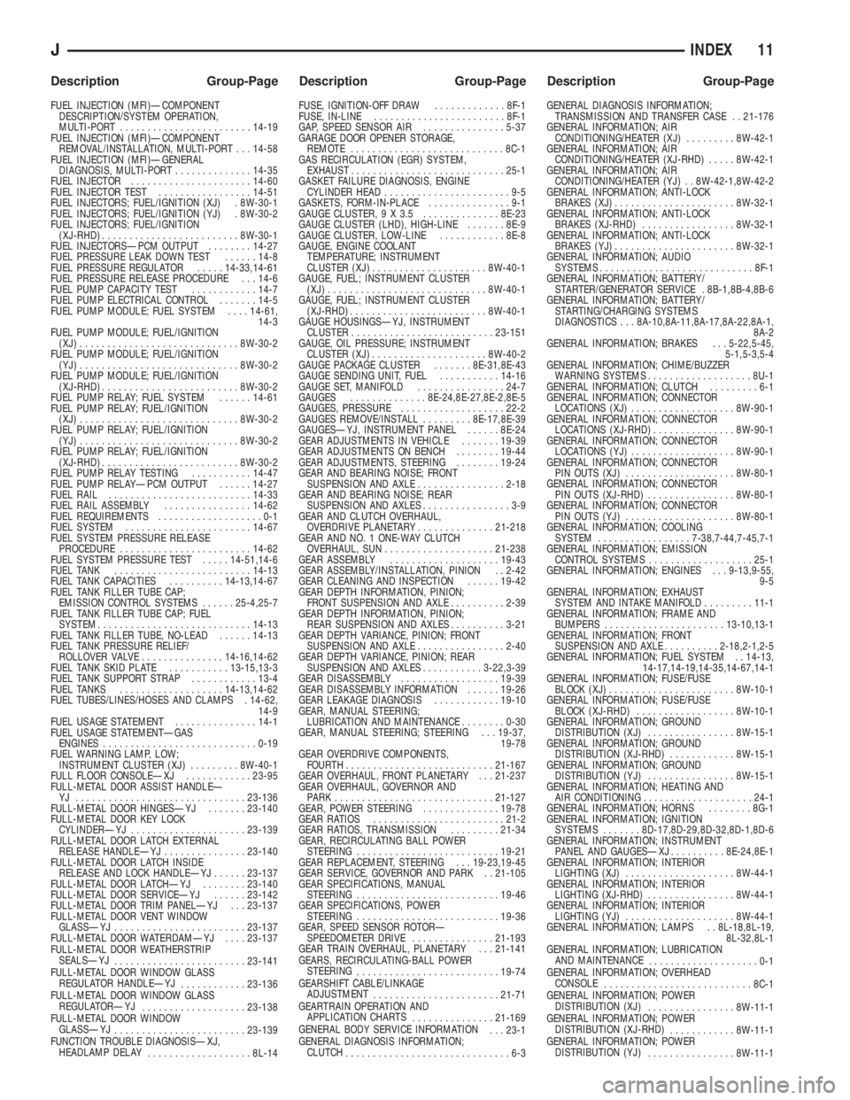
FUEL INJECTION (MFI)ÐCOMPONENT
DESCRIPTION/SYSTEM OPERATION,
MULTI-PORT........................14-19
FUEL INJECTION (MFI)ÐCOMPONENT
REMOVAL/INSTALLATION, MULTI-PORT . . . 14-58
FUEL INJECTION (MFI)ÐGENERAL
DIAGNOSIS, MULTI-PORT..............14-35
FUEL INJECTOR......................14-60
FUEL INJECTOR TEST.................14-51
FUEL INJECTORS; FUEL/IGNITION (XJ) . 8W-30-1
FUEL INJECTORS; FUEL/IGNITION (YJ) . 8W-30-2
FUEL INJECTORS; FUEL/IGNITION
(XJ-RHD).........................8W-30-1
FUEL INJECTORSÐPCM OUTPUT........14-27
FUEL PRESSURE LEAK DOWN TEST......14-8
FUEL PRESSURE REGULATOR.....14-33,14-61
FUEL PRESSURE RELEASE PROCEDURE . . . 14-6
FUEL PUMP CAPACITY TEST............14-7
FUEL PUMP ELECTRICAL CONTROL.......14-5
FUEL PUMP MODULE; FUEL SYSTEM....14-61,
14-3
FUEL PUMP MODULE; FUEL/IGNITION
(XJ).............................8W-30-2
FUEL PUMP MODULE; FUEL/IGNITION
(YJ).............................8W-30-2
FUEL PUMP MODULE; FUEL/IGNITION
(XJ-RHD).........................8W-30-2
FUEL PUMP RELAY; FUEL SYSTEM......14-61
FUEL PUMP RELAY; FUEL/IGNITION
(XJ).............................8W-30-2
FUEL PUMP RELAY; FUEL/IGNITION
(YJ).............................8W-30-2
FUEL PUMP RELAY; FUEL/IGNITION
(XJ-RHD).........................8W-30-2
FUEL PUMP RELAY TESTING...........14-47
FUEL PUMP RELAYÐPCM OUTPUT......14-27
FUEL RAIL..........................14-33
FUEL RAIL ASSEMBLY................14-62
FUEL REQUIREMENTS...................0-1
FUEL SYSTEM.......................14-67
FUEL SYSTEM PRESSURE RELEASE
PROCEDURE........................14-62
FUEL SYSTEM PRESSURE TEST.....14-51,14-6
FUEL TANK.........................14-13
FUEL TANK CAPACITIES..........14-13,14-67
FUEL TANK FILLER TUBE CAP;
EMISSION CONTROL SYSTEMS......25-4,25-7
FUEL TANK FILLER TUBE CAP; FUEL
SYSTEM............................14-13
FUEL TANK FILLER TUBE, NO-LEAD......14-13
FUEL TANK PRESSURE RELIEF/
ROLLOVER VALVE...............14-16,14-62
FUEL TANK SKID PLATE...........13-15,13-3
FUEL TANK SUPPORT STRAP............13-4
FUEL TANKS...................14-13,14-62
FUEL TUBES/LINES/HOSES AND CLAMPS . 14-62,
14-9
FUEL USAGE STATEMENT...............14-1
FUEL USAGE STATEMENTÐGAS
ENGINES............................0-19
FUEL WARNING LAMP, LOW;
INSTRUMENT CLUSTER (XJ).........8W-40-1
FULL FLOOR CONSOLEÐXJ............23-95
FULL-METAL DOOR ASSIST HANDLEÐ
YJ ...............................23-136
FULL-METAL DOOR HINGESÐYJ.......23-140
FULL-METAL DOOR KEY LOCK
CYLINDERÐYJ.....................23-139
FULL-METAL DOOR LATCH EXTERNAL
RELEASE HANDLEÐYJ...............23-140
FULL-METAL DOOR LATCH INSIDE
RELEASE AND LOCK HANDLEÐYJ......23-137
FULL-METAL DOOR LATCHÐYJ........23-140
FULL-METAL DOOR SERVICEÐYJ......23-142
FULL-METAL DOOR TRIM PANELÐYJ . . . 23-137
FULL-METAL DOOR VENT WINDOW
GLASSÐYJ........................23-137
FULL-METAL DOOR WATERDAMÐYJ....23-137
FULL-METAL DOOR WEATHERSTRIP
SEALSÐYJ
........................23-141
FULL-METAL DOOR WINDOW GLASS
REGULATOR HANDLEÐYJ
............23-136
FULL-METAL DOOR WINDOW GLASS
REGULATORÐYJ
...................23-138
FULL-METAL DOOR WINDOW
GLASSÐYJ
........................23-139
FUNCTION TROUBLE DIAGNOSISÐXJ,
HEADLAMP DELAY
...................8L-14FUSE, IGNITION-OFF DRAW.............8F-1
FUSE, IN-LINE........................8F-1
GAP, SPEED SENSOR AIR...............5-37
GARAGE DOOR OPENER STORAGE,
REMOTE............................8C-1
GAS RECIRCULATION (EGR) SYSTEM,
EXHAUST............................25-1
GASKET FAILURE DIAGNOSIS, ENGINE
CYLINDER HEAD.......................9-5
GASKETS, FORM-IN-PLACE...............9-1
GAUGE CLUSTER, 9 X 3.5 ..............8E-23
GAUGE CLUSTER (LHD), HIGH-LINE.......8E-9
GAUGE CLUSTER, LOW-LINE............8E-8
GAUGE, ENGINE COOLANT
TEMPERATURE; INSTRUMENT
CLUSTER (XJ).....................8W-40-1
GAUGE, FUEL; INSTRUMENT CLUSTER
(XJ).............................8W-40-1
GAUGE, FUEL; INSTRUMENT CLUSTER
(XJ-RHD).........................8W-40-1
GAUGE HOUSINGSÐYJ, INSTRUMENT
CLUSTER..........................23-151
GAUGE, OIL PRESSURE; INSTRUMENT
CLUSTER (XJ).....................8W-40-2
GAUGE PACKAGE CLUSTER.......8E-31,8E-43
GAUGE SENDING UNIT, FUEL...........14-16
GAUGE SET, MANIFOLD................24-7
GAUGES..............8E-24,8E-27,8E-2,8E-5
GAUGES, PRESSURE...................22-2
GAUGES REMOVE/INSTALL.........8E-17,8E-39
GAUGESÐYJ, INSTRUMENT PANEL......8E-24
GEAR ADJUSTMENTS IN VEHICLE.......19-39
GEAR ADJUSTMENTS ON BENCH........19-44
GEAR ADJUSTMENTS, STEERING........19-24
GEAR AND BEARING NOISE; FRONT
SUSPENSION AND AXLE................2-18
GEAR AND BEARING NOISE; REAR
SUSPENSION AND AXLES................3-9
GEAR AND CLUTCH OVERHAUL,
OVERDRIVE PLANETARY..............21-218
GEAR AND NO. 1 ONE-WAY CLUTCH
OVERHAUL, SUN....................21-238
GEAR ASSEMBLY....................19-43
GEAR ASSEMBLY/INSTALLATION, PINION . . 2-42
GEAR CLEANING AND INSPECTION......19-42
GEAR DEPTH INFORMATION, PINION;
FRONT SUSPENSION AND AXLE..........2-39
GEAR DEPTH INFORMATION, PINION;
REAR SUSPENSION AND AXLES..........3-21
GEAR DEPTH VARIANCE, PINION; FRONT
SUSPENSION AND AXLE................2-40
GEAR DEPTH VARIANCE, PINION; REAR
SUSPENSION AND AXLES...........3-22,3-39
GEAR DISASSEMBLY..................19-39
GEAR DISASSEMBLY INFORMATION......19-26
GEAR LEAKAGE DIAGNOSIS............19-10
GEAR, MANUAL STEERING;
LUBRICATION AND MAINTENANCE........0-30
GEAR, MANUAL STEERING; STEERING . . . 19-37,
19-78
GEAR OVERDRIVE COMPONENTS,
FOURTH...........................21-167
GEAR OVERHAUL, FRONT PLANETARY . . . 21-237
GEAR OVERHAUL, GOVERNOR AND
PARK .............................21-127
GEAR, POWER STEERING..............19-78
GEAR RATIOS........................21-2
GEAR RATIOS, TRANSMISSION.........21-34
GEAR, RECIRCULATING BALL POWER
STEERING..........................19-21
GEAR REPLACEMENT, STEERING . . . 19-23,19-45
GEAR SERVICE, GOVERNOR AND PARK . . 21-105
GEAR SPECIFICATIONS, MANUAL
STEERING..........................19-46
GEAR SPECIFICATIONS, POWER
STEERING..........................19-36
GEAR, SPEED SENSOR ROTORÐ
SPEEDOMETER DRIVE...............21-193
GEAR TRAIN OVERHAUL, PLANETARY . . . 21-141
GEARS, RECIRCULATING-BALL POWER
STEERING
..........................19-74
GEARSHIFT CABLE/LINKAGE
ADJUSTMENT
.......................21-71
GEARTRAIN OPERATION AND
APPLICATION CHARTS
...............21-169
GENERAL BODY SERVICE INFORMATION
. . . 23-1
GENERAL DIAGNOSIS INFORMATION;
CLUTCH
..............................6-3GENERAL DIAGNOSIS INFORMATION;
TRANSMISSION AND TRANSFER CASE . . 21-176
GENERAL INFORMATION; AIR
CONDITIONING/HEATER (XJ).........8W-42-1
GENERAL INFORMATION; AIR
CONDITIONING/HEATER (XJ-RHD).....8W-42-1
GENERAL INFORMATION; AIR
CONDITIONING/HEATER (YJ) . . 8W-42-1,8W-42-2
GENERAL INFORMATION; ANTI-LOCK
BRAKES (XJ)......................8W-32-1
GENERAL INFORMATION; ANTI-LOCK
BRAKES (XJ-RHD).................8W-32-1
GENERAL INFORMATION; ANTI-LOCK
BRAKES (YJ)......................8W-32-1
GENERAL INFORMATION; AUDIO
SYSTEMS............................8F-1
GENERAL INFORMATION; BATTERY/
STARTER/GENERATOR SERVICE . 8B-1,8B-4,8B-6
GENERAL INFORMATION; BATTERY/
STARTING/CHARGING SYSTEMS
DIAGNOSTICS . . . 8A-10,8A-11,8A-17,8A-22,8A-1,
8A-2
GENERAL INFORMATION; BRAKES . . . 5-22,5-45,
5-1,5-3,5-4
GENERAL INFORMATION; CHIME/BUZZER
WARNING SYSTEMS...................8U-1
GENERAL INFORMATION; CLUTCH.........6-1
GENERAL INFORMATION; CONNECTOR
LOCATIONS (XJ)...................8W-90-1
GENERAL INFORMATION; CONNECTOR
LOCATIONS (XJ-RHD)...............8W-90-1
GENERAL INFORMATION; CONNECTOR
LOCATIONS (YJ)...................8W-90-1
GENERAL INFORMATION; CONNECTOR
PIN OUTS (XJ)....................8W-80-1
GENERAL INFORMATION; CONNECTOR
PIN OUTS (XJ-RHD)................8W-80-1
GENERAL INFORMATION; CONNECTOR
PIN OUTS (YJ)....................8W-80-1
GENERAL INFORMATION; COOLING
SYSTEM.................7-38,7-44,7-45,7-1
GENERAL INFORMATION; EMISSION
CONTROL SYSTEMS...................25-1
GENERAL INFORMATION; ENGINES . . . 9-13,9-55,
9-5
GENERAL INFORMATION; EXHAUST
SYSTEM AND INTAKE MANIFOLD.........11-1
GENERAL INFORMATION; FRAME AND
BUMPERS......................13-10,13-1
GENERAL INFORMATION; FRONT
SUSPENSION AND AXLE..........2-18,2-1,2-5
GENERAL INFORMATION; FUEL SYSTEM . . 14-13,
14-17,14-19,14-35,14-67,14-1
GENERAL INFORMATION; FUSE/FUSE
BLOCK (XJ).......................8W-10-1
GENERAL INFORMATION; FUSE/FUSE
BLOCK (XJ-RHD)..................8W-10-1
GENERAL INFORMATION; GROUND
DISTRIBUTION (XJ)................8W-15-1
GENERAL INFORMATION; GROUND
DISTRIBUTION (XJ-RHD)............8W-15-1
GENERAL INFORMATION; GROUND
DISTRIBUTION (YJ)................8W-15-1
GENERAL INFORMATION; HEATING AND
AIR CONDITIONING....................24-1
GENERAL INFORMATION; HORNS........8G-1
GENERAL INFORMATION; IGNITION
SYSTEMS.......8D-17,8D-29,8D-32,8D-1,8D-6
GENERAL INFORMATION; INSTRUMENT
PANEL AND GAUGESÐXJ..........8E-24,8E-1
GENERAL INFORMATION; INTERIOR
LIGHTING (XJ)....................8W-44-1
GENERAL INFORMATION; INTERIOR
LIGHTING (XJ-RHD)................8W-44-1
GENERAL INFORMATION; INTERIOR
LIGHTING (YJ)....................8W-44-1
GENERAL INFORMATION; LAMPS . . 8L-18,8L-19,
8L-32,8L-1
GENERAL INFORMATION; LUBRICATION
AND MAINTENANCE
....................0-1
GENERAL INFORMATION; OVERHEAD
CONSOLE
...........................8C-1
GENERAL INFORMATION; POWER
DISTRIBUTION (XJ)
................8W-11-1
GENERAL INFORMATION; POWER
DISTRIBUTION (XJ-RHD)
............8W-11-1
GENERAL INFORMATION; POWER
DISTRIBUTION (YJ)
................8W-11-1
JINDEX 11
Description Group-Page Description Group-Page Description Group-Page