1995 JEEP XJ ECO mode
[x] Cancel search: ECO modePage 445 of 2158
The liftgate wiper motor can not be repaired. If
faulty, the entire assembly must be replaced.
WINDSHIELD WIPER/WASHER SWITCH
Controls for the windshield wiper and washer sys-
tems are contained in the turn signal switch lever.
The turn signal switch lever is mounted on the left
side of the steering column between the steering
wheel and the instrument panel. The wiper/washer
switch can not be repaired. If any function of the
switch is faulty, the entire switch must be replaced.
LIFTGATE WIPER/WASHER SWITCH
The single two-function switch on the instrument
panel right of the steering column controls the lift-
gate wiper and washer functions. The rocker-type
switch features a detent in the WIPE position, but
only momentary contact in the WASH position. Both
the liftgate wiper and liftgate washer motors will op-
erate continuously for as long as the switch is held in
the WASH position. The switch can not be repaired;
if faulty, it must be replaced.
INTERMITTENT WIPE MODULE
In addition to low and high speed, the optional in-
termittent wipe system has a delay mode. The delay
mode has a range of 2 to 15 seconds. The length of
the delay is selected with a variable resistor in the
wiper switch and is accomplished by electronic cir-
cuitry within the intermittent wipe module. If the
washer knob is depressed while the wiper switch is
in the OFF position, the intermittent wipe module
will operate the wiper motor for approximately 2
wipes and automatically turn the motor off.
The intermittent wipe module is mounted to a
bracket behind the lower instrument panel, near the
steering column with a hook and loop fastener patch.
The module can not be repaired.
WINDSHIELD WASHER NOZZLES
The two fluidic washer nozzles are screwed into
openings in the cowl panel below the windshield and
are not adjustable. Washer fluid is fed to the nozzles
through hoses underneath the cowl panel. The noz-
zles can not be repaired and, if faulty, should be re-
placed.
LIFTGATE WASHER NOZZLE
The single liftgate washer nozzle is installed
through the liftgate glass and secured with a nut on
the inside of the glass. Washer fluid is fed to the noz-
zle from the washer reservoir in the engine compart-
ment. A liftgate washer hose system is routed
through the body of the vehicle with the body wiring
harness from the reservoir to the liftgate. The nozzle
can not be repaired and, if faulty, should be replaced.
WASHER RESERVOIR
The washer solvent reservoir is mounted with a
bracket to the left front inner fender shield near the
cowl panel. The same reservoir is used for both the
standard front and optional liftgate washer systems.
The reservoir and filler cap are available for service.
WASHER PUMPS
The washer pump and motor are press-fit into a
rubber grommet near the bottom of the washer res-
ervoir. Vehicles with the optional liftgate wiper/
washer system have two pumps installed in the
single reservoir. A permanently lubricated and sealed
motor is coupled to a rotor-type pump. Washer fluid
is gravity fed from the reservoir to the pump. The
pump then pressurizes the fluid and forces it through
the plumbing to the nozzles when the motor is ener-
gized. The pump and motor can not be repaired. If
faulty, the entire assembly must be replaced.
JWIPER AND WASHER SYSTEMS - YJ 8K - 11
Page 497 of 2158
REAR WINDOW DEFOGGER
CONTENTS
page page
DIAGNOSIS............................. 1
GENERAL INFORMATION.................. 1SERVICE PROCEDURES................... 3
GENERAL INFORMATION
The electrically-heated rear window defogger is an
available option on XJ (Cherokee), and YJ (Wrangler)
models equipped with the hardtop roof option. Fol-
lowing are general descriptions of the major compo-
nents in the rear window defogger system. Refer to
Group 8W - Wiring Diagrams for complete circuit de-
scriptions and diagrams.
REAR WINDOW GLASS GRID
The heated rear window glass has two electrically-
conductive vertical bus bars and a series of horizon-
tal grid lines made of a silver-ceramic material,
which is baked on and bonded to the inside surface of
the glass. The grid lines and bus bars comprise a
parallel electrical circuit.
When the rear window defogger switch is placed in
the ON position, current is directed to the rear win-
dow grid lines through the bus bars. The grid lines
heat the rear window to clear the surface of fog or
snow. Circuit protection for the heated grid circuit is
provided by fuse 18 (XJ) or fuse 6 (YJ) in the fuse-
block module.
The grid lines and bus bars are highly resistant to
abrasion. However, it is possible for an open to occur
in an individual grid line resulting in no current flow
through the line. The grid lines can be damaged or
scraped off with sharp instruments. Care should be
taken in cleaning the glass or removing foreign ma-
terials, decals or stickers. Normal glass cleaning sol-
vents or hot water used with rags or toweling is
recommended.A repair kit is available to repair the grid lines and
bus bars, or to reinstall the heated glass pigtail
wires.
DEFOGGER SWITCH
The rear window defogger switch is mounted in the
instrument panel left of the steering column for XJ,
or right of the steering column for YJ. The switch cir-
cuit is protected by fuse 8 (XJ) or fuse 9 (YJ) in the
fuseblock module. Actuating the switch energizes the
relay and electronic timer. A light-emitting diode
(LED) in the switch (XJ), or a indicator lamp in the
switch (YJ), illuminates to indicate when the system
is turned on. The defogger switch can not be re-
paired. If faulty, the switch must be replaced.
DEFOGGER RELAY/TIMER
The defogger relay/timer is located in the relay cen-
ter on XJ models, or taped to the instrument panel
wiring harness behind the parking brake pedal in the
left cowl side area on YJ models. When the rear de-
fogger switch is actuated, the rear defogger relay is
energized. This causes current to flow through the
grid circuit for approximately 10 minutes, or until
the rear window defogger switch or ignition switch
are turned off.
DIAGNOSIS
SYSTEM TESTS
Electrically-heated rear window defogger operation
can be confirmed in the following manner:
(1) Turn the ignition switch to the ON position.
(2) Turn rear window defogger control switch ON.
(3) Monitor vehicle voltmeter. With the control
switch ON, a distinct needle deflection should be
noted.(4) The rear window defogger operation can be
checked by feeling the glass. A distinct difference in
temperature between the grid lines and adjacent
clear glass can be detected within 3 to 4 minutes of
operation.
(5) Using a DC voltmeter, contact terminal A (Fig.
1) (passenger side) with the negative lead, and termi-
JREAR WINDOW DEFOGGER 8N - 1
Page 525 of 2158
POWER MIRRORS
CONTENTS
page page
DIAGNOSIS............................. 1
GENERAL INFORMATION.................. 1SERVICE PROCEDURES................... 4
GENERAL INFORMATION
Power outside rear view mirrors are an available
option on XJ (Cherokee) models. Following are gen-
eral descriptions of the major components in the
power mirror system. Refer to Group 8W - Wiring Di-
agrams for complete circuit descriptions and dia-
grams.
POWER MIRROR
The power mirrors are connected to battery feed at
all times. Each mirror head contains two electric mo-
tors, two drive mechanisms and the mirror glass.
One motor and drive controls mirror up-and-down
movement, and the other controls right-and-left
movement.
The mirror glass is the only serviced replacement
part for the power mirror assembly. If any other com-ponent of the mirror unit is faulty or damaged, the
entire assembly must be replaced.
POWER MIRROR SWITCH
Both the right and left mirror are controlled by a
multi-function switch located on the front of the cen-
ter console storage compartment, directly below the
armrest. The selector switch is moved right (right
mirror control), left (left mirror control), or center to
turn power mirrors off. Then one of four directional
control buttons is depressed to control movement of
the selected mirror up, down, right, or left. The
power mirror switch is serviced only as a complete
unit.
DIAGNOSIS
POWER MIRROR SYSTEM
(1) Check fuse 16 in Power Distribution Center
(PDC) and fuse 9 in fuseblock module. If OK, go to
next step. If not OK, replace fuse.
(2) Check for battery voltage at fuse 9 in fuseblock
module. If OK, go to next step. If not OK, repair cir-
cuit to fuse 16 in PDC.
(3) Remove power mirror switch from the center
console. See Power Mirror Switch Remove/Install.
(4) Disconnect wiring harness connector from
switch. Check for battery voltage at pink wire. If OK,
go to next step. If not OK, repair circuit to fuse 9 in
fuseblock module.
(5) Check for continuity between black wire in
switch harness connector and a good ground. There
should be continuity. If OK, go to next step. If not
OK, repair circuit to ground.
(6) Check switch continuity as shown in the Mirror
Switch Continuity charts. If OK, go to next step. If
not OK, replace switch.(7) See Power Mirror Switch illustration. Connect
a jumper wire from mirror switch connector cavity
for pin E to cavity for pin F. Now connect a second
jumper from connector cavity for pin G to each of the
following pin cavities: A, B, C, then D. In each case,
the selected mirror head should move. If OK, replace
switch. If not OK, go to next step.
(8) Remove door trim panel and unplug power mir-
ror connector inside door. Connect one jumper wire to
a good ground and a second jumper wire to a battery
feed. Connect other ends of jumpers to the mirror
side of connector in door (refer to Group 8W - Wiring
Diagrams for connector cavity identification). Mirror
head should move in each of the four directions. If
OK, repair wiring between mirror switch and door
connectors. If not OK, replace mirror.
JPOWER MIRRORS 8T - 1
Page 531 of 2158
CHIME/BUZZER WARNING SYSTEMS
CONTENTS
page page
DIAGNOSIS............................. 2
GENERAL INFORMATION.................. 1SERVICE PROCEDURES................... 4
GENERAL INFORMATION
This group covers the buzzer warning system,
which is standard equipment on XJ (Cherokee)/YJ
(Wrangler) models. The system provides an audible
warning to the driver when it monitors the following
conditions:
²key is in ignition switch with the driver's door
open
²head or park lamps are on with driver's door open
(XJ only)
²driver's seat belt is not buckled with ignition
switch in ON position.
Following are general descriptions of the major
components in the buzzer warning system. Refer to
Group 8W - Wiring Diagrams for complete circuit de-
scriptions and diagrams.
BUZZER MODULE
The buzzer module is located in the fuseblock mod-
ule under the left end of the instrument panel. It re-
ceives battery voltage at all times from (fuse 15 - XJ,
fuse 3 - YJ) the fuseblock module. It also receives a
second battery feed (fuse 17 - XJ, fuse 9 - YJ) when
the ignition switch is in the ON or START position.
Other inputs to the module include the driver's door
jamb switch, the driver's seat belt switch, the ignition
key-in switch, and the headlamp switch (XJ only). The
only output of the module is a timed 4 to 8 second feed
to the seat belt reminder lamp in the message center of
the instrument cluster. The timer function begins after
the ignition switch is turned to the ON position.
The buzzer module can not be repaired. If faulty, it
must be replaced.
DRIVER'S DOOR JAMB SWITCH
The driver's door jamb switch is mounted to the
driver's door hinge pillar. The switch closes a path to
ground for the buzzer module through the key-in
switch or headlamp switch (XJ only) when the driv-
er's door is opened, and opens when the driver's door
is closed. This switch can not be repaired. If faulty, it
must be replaced.
IGNITION KEY-IN SWITCH
XJ MODELS
The key-in switch is integral to the ignition switch,
which is mounted on the right side of the steering col-
umn. It closes a path to ground for the buzzer module
when the ignition key is inserted in the ignition lock cyl-
inder and the driver's door jamb switch is closed (door
open). The switch opens when the key is removed from
the ignition lock cylinder. This switch can not be re-
paired. If faulty, the entire ignition switch must be re-
placed. Refer to Group 8D - Ignition Systems for service
procedures.
YJ MODELS
The key-in switch is mounted within the steering col-
umn in the lock cylinder housing. It closes a path to
ground for the buzzer module when the ignition key is
inserted in the ignition lock cylinder and the driver's
door jamb switch is closed (door open). The switch opens
when the key is removed from the ignition lock cylinder.
This switch is available for service replacement. Refer
to Group 19 - Steering for service procedures.
HEADLAMP SWITCH (XJ ONLY)
The headlamp switch is located in the instrument
panel. It closes a path to ground for the buzzer module
when the park or headlamps are on and the driver's
door jamb switch is closed (door open). The switch opens
the ground path when the park and headlamps are
turned off. The headlamp switch can not be repaired. If
faulty, it must be replaced. Refer to Group 8E - Instru-
ment Panel and Gauges for service procedures.
DRIVER'S SEAT BELT SWITCH
The driver's seat belt switch is integral to the driv-
er's seat belt buckle-half assembly. The switch is nor-
mally closed, providing a ground path to the buzzer
module. When the tip-half of the seat belt is inserted
into the seat belt buckle, the switch opens the buzzer
module ground path. The seat belt switch can not be
repaired. If faulty, the entire driver's seat belt buck-
le-half must be replaced. Refer to Group 23 - Body
Components for service procedures.
JCHIME/BUZZER WARNING SYSTEMS 8U - 1
Page 535 of 2158
WIRING DIAGRAMSÐGENERAL INFORMATION
INDEX
page page
Circuit Identification......................... 1
Connector and Terminal Replacement........... 7
Connector Replacement..................... 6
Connectors............................... 2
Diode Replacement........................ 8
Electrostatic Discharge (ESC) Sensitive Devices . . . 2
General Information......................... 1
Intermittent and Poor Connections.............. 4
Notes, Cautions, and Warnings................ 1Symbols................................. 2
Take Outs................................ 2
Terminal Replacement....................... 8
Terminal/Connector RepairÐMolex Connectors.... 6
Troubleshooting Tests....................... 4
Troubleshooting Tools....................... 4
Troubleshooting Wiring Problems.............. 5
Wire Code Identification..................... 1
Wiring Repair............................. 6
GENERAL INFORMATION
This Group is divided into three stand alone sec-
tions; XJ, YJ, and XJ Right Hand Drive (XJ-RHD).
Separate circuit descriptions and wiring diagrams are
provided for each vehicle. Each section contains a
Contents list for the wiring diagrams and circuit de-
scriptions for that vehicle.
The complete XJ circuit descriptions and diagrams
are printed first, followed by those for the YJ and
then the XJ-RHD. The heading at the top of each
page identifies the vehicle covered in the section.
NOTES, CAUTIONS, and WARNINGS
Throughout this group additional important infor-
mation is presented in three ways; Notes, Cautions,
and Warnings.
NOTESare used to help describe how switches or
components operate to complete a particular circuit.
They are also used to indicate different conditions
that may appear on the vehicle. For example, an
up-to and after condition.
CAUTIONSare used to indicate information that
could prevent making an error that may damage the
vehicle.
WARNINGSprovide information to prevent per-
sonal injury and vehicle damage. Below is a list of
general warnings that should be followed any time a
vehicle is being serviced.
ALWAYS WEAR SAFETY GLASSES FOR EYE PRO-
TECTION.
USE SAFETY STANDS ANYTIME A PROCEDURE RE-
QUIRES BEING UNDER A VEHICLE.
BE SURE THAT THE IGNITION SWITCH ALWAYS IS
IN THE OFF POSITION, UNLESS THE PROCEDURE
REQUIRES IT TO BE ON.SET THE PARKING BRAKE WHEN WORKING ON
ANY VEHICLE. AN AUTOMATIC TRANSMISSION
SHOULD BE IN PARK. A MANUAL TRANSMISSION
SHOULD BE IN NEUTRAL.
OPERATE THE ENGINE ONLY IN A WELL-VENTI-
LATED AREA.
KEEP AWAY FROM MOVING PARTS WHEN THE EN-
GINE IS RUNNING, ESPECIALLY THE FAN AND BELTS.
TO PREVENT SERIOUS BURNS, AVOID CONTACT
WITH HOT PARTS SUCH AS THE RADIATOR, EX-
HAUST MANIFOLD(S), TAIL PIPE, CATALYTIC CON-
VERTER, AND MUFFLER.
DO NOT ALLOW FLAME OR SPARKS NEAR THE
BATTERY. GASES ARE ALWAYS PRESENT IN AND
AROUND THE BATTERY.
ALWAYS REMOVE RINGS, WATCHES, LOOSE
HANGING JEWELRY, AND LOOSE CLOTHING.
WIRE CODE IDENTIFICATION
Each wire shown in the diagrams contains a code
(Fig. 1) which identifies the main circuit, part of the
main circuit, gauge of wire, and color. The color is
shown as a two letter code which can be identified by
referring to the Wire Color Code Chart (Fig. 2).
CIRCUIT IDENTIFICATION
All circuits in the diagrams use an alpha/numeric
code to identify the wire and its function (Fig. 3). To
identify which circuit code applies to a system, refer
to the Circuit Identification Code Chart. This chart
shows the main circuits only and does not show the
secondary codes that may apply to some models.
JWIRING DIAGRAMSÐGENERAL INFORMATION 8W - 1
Page 1403 of 2158
FUEL SYSTEM
CONTENTS
page page
ACCELERATOR PEDAL AND THROTTLE CABLE.17
FUEL DELIVERY SYSTEM.................. 3
FUEL TANKS........................... 13
GENERAL INFORMATION.................. 1
MULTI-PORT FUEL INJECTION (MFI)Ð
COMPONENT DESCRIPTION/SYSTEMOPERATION.......................... 19
MULTI-PORT FUEL INJECTION (MFI)Ð
COMPONENT REMOVAL/INSTALLATION.... 58
MULTI-PORT FUEL INJECTION (MFI)Ð
GENERAL DIAGNOSIS.................. 35
SPECIFICATIONS........................ 67
GENERAL INFORMATION
Throughout this group, references are made to par-
ticular vehicle models by alphabetical designation
(XJ or YJ) or by the particular vehicle nameplate. A
chart showing a breakdown of the alphabetical desig-
nations is included in the Introduction section at the
beginning of this manual.
TheFuel Systemconsists of: the fuel tank, an
electric (fuel tank mounted) fuel pump and a fuel fil-
ter. It also consists of fuel tubes/lines/hoses, vacuum
hoses, throttle body and fuel injectors.
TheFuel Delivery Systemconsists of: the electric
fuel pump, fuel filter, fuel tubes/lines/hoses, fuel rail,
fuel injectors and fuel pressure regulator.
AFuel Return Systemis used on all vehicles.
The system consists of: the fuel tubes/lines/hoses that
route fuel back to the fuel tank.
TheFuel Tank Assemblyconsists of: the fuel
tank, filler tube, fuel fill and vent hoses, fuel gauge
sending unit/electric fuel pump module, a pressure
relief/rollover valve and a pressure-vacuum filler cap.
Also to be considered part of the fuel system is the
Evaporation Control System.This is designed to
reduce the emission of fuel vapors into the atmo-
sphere. The description and function of the Evapora-
tive Control System is found in Group 25, Emission
Control Systems.
FUEL USAGE STATEMENT
Your vehicle was designed to meet all emission reg-
ulations and provide excellent fuel economy using
high quality unleaded gasoline. Only use unleaded
gasolines having a minimum posted octane of 87.
If your vehicle develops occasional light spark
knock (ping) at low engine speeds, this is not harm-
ful. However,continued heavy knock at high
speeds can cause damage and should be re-
ported to your dealer immediately.Engine dam-
age as a result of heavy knock operation may not becovered by the new vehicle warranty.
In addition to using unleaded gasoline with the
proper octane rating,those that contain deter-
gents, corrosion and stability additives are rec-
ommended.Using gasolines that have these
additives will help improve fuel economy, reduce
emissions and maintain vehicle performance.
Poor quality gasolinecan cause problems such
as hard starting, stalling and stumble. If you experi-
ence these problems, use another brand of gasoline
before considering service for the vehicle.
GASOLINE/OXYGENATE BLENDS
Some fuel suppliers blend unleaded gasoline with
materials that contain oxygen such as alcohol, MTBE
and ETBE. The type and amount of oxygenate used
in the blend is important. The following are generally
used in gasoline blends:
ETHANOL
Ethanol (Ethyl or Grain Alcohol) properly blended,
is used as a mixture of 10 percent ethanol and 90
percent gasoline.Gasoline with ethanol may be
used in your vehicle.
METHANOL
CAUTION: DO NOT USE GASOLINES CONTAINING
METHANOL.Use of methanol/gasoline blends may re-
sult in starting and driveability problems. In addition,
damage may be done to critical fuel system compo-
nents.
Methanol (Methyl or Wood Alcohol) is used in a va-
riety of concentrations blended with unleaded gaso-
JFUEL SYSTEM 14 - 1
Page 1428 of 2158
AIR CONDITIONING (A/C) CLUTCH RELAYÐPCM
OUTPUT
The powertrain control module (PCM) activates the
A/C compressor through the A/C clutch relay. The
PCM regulates A/C compressor operation by switch-
ing the ground circuit for the A/C clutch relay on and
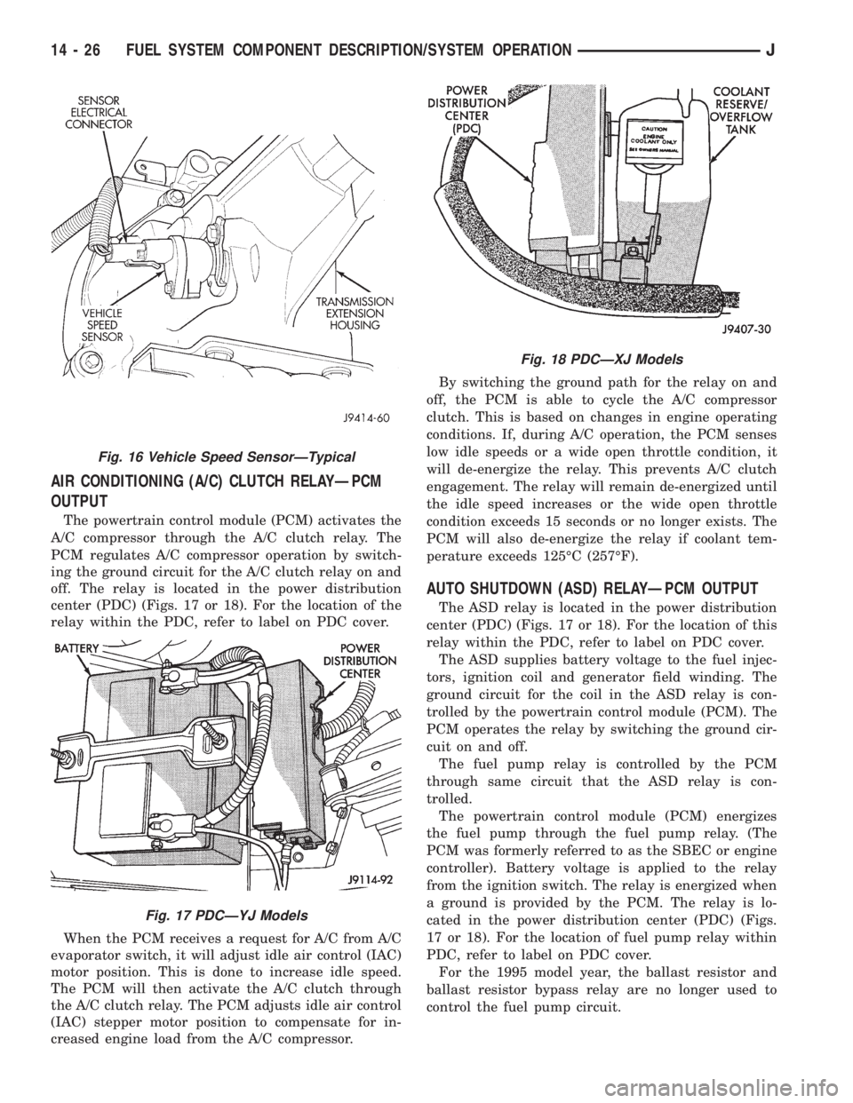
off. The relay is located in the power distribution
center (PDC) (Figs. 17 or 18). For the location of the
relay within the PDC, refer to label on PDC cover.
When the PCM receives a request for A/C from A/C
evaporator switch, it will adjust idle air control (IAC)
motor position. This is done to increase idle speed.
The PCM will then activate the A/C clutch through
the A/C clutch relay. The PCM adjusts idle air control
(IAC) stepper motor position to compensate for in-
creased engine load from the A/C compressor.By switching the ground path for the relay on and
off, the PCM is able to cycle the A/C compressor
clutch. This is based on changes in engine operating
conditions. If, during A/C operation, the PCM senses
low idle speeds or a wide open throttle condition, it
will de-energize the relay. This prevents A/C clutch
engagement. The relay will remain de-energized until
the idle speed increases or the wide open throttle
condition exceeds 15 seconds or no longer exists. The
PCM will also de-energize the relay if coolant tem-
perature exceeds 125ÉC (257ÉF).
AUTO SHUTDOWN (ASD) RELAYÐPCM OUTPUT
The ASD relay is located in the power distribution
center (PDC) (Figs. 17 or 18). For the location of this
relay within the PDC, refer to label on PDC cover.
The ASD supplies battery voltage to the fuel injec-
tors, ignition coil and generator field winding. The
ground circuit for the coil in the ASD relay is con-
trolled by the powertrain control module (PCM). The
PCM operates the relay by switching the ground cir-
cuit on and off.
The fuel pump relay is controlled by the PCM
through same circuit that the ASD relay is con-
trolled.
The powertrain control module (PCM) energizes
the fuel pump through the fuel pump relay. (The
PCM was formerly referred to as the SBEC or engine
controller). Battery voltage is applied to the relay
from the ignition switch. The relay is energized when
a ground is provided by the PCM. The relay is lo-
cated in the power distribution center (PDC) (Figs.
17 or 18). For the location of fuel pump relay within
PDC, refer to label on PDC cover.
For the 1995 model year, the ballast resistor and
ballast resistor bypass relay are no longer used to
control the fuel pump circuit.
Fig. 16 Vehicle Speed SensorÐTypical
Fig. 17 PDCÐYJ Models
Fig. 18 PDCÐXJ Models
14 - 26 FUEL SYSTEM COMPONENT DESCRIPTION/SYSTEM OPERATIONJ
Page 1430 of 2158
The throttle body has an air control passage that
provides air for the engine at idle (the throttle plate
is closed). The IAC motor pintle protrudes into the
air control passage and regulates air flow through it.
Based on various sensor inputs, the powertrain con-
trol module (PCM) adjusts engine idle speed by mov-
ing the IAC motor pintle in and out of the air control
passage. The IAC motor is positioned when the igni-
tion key is turned to the On position.
A (factory adjusted) set screw is used to mechani-
cally limit the position of the throttle body throttle
plate.Never attempt to adjust the engine idle
speed using this screw.All idle speed functions are
controlled by the PCM.
IGNITION COILÐPCM OUTPUT
System voltage is supplied to the ignition coil pos-
itive terminal. The powertrain control module (PCM)
operates the ignition coil.Base (initial) ignition
timing is not adjustable.The PCM adjusts ignition
timing to meet changing engine operating conditions.
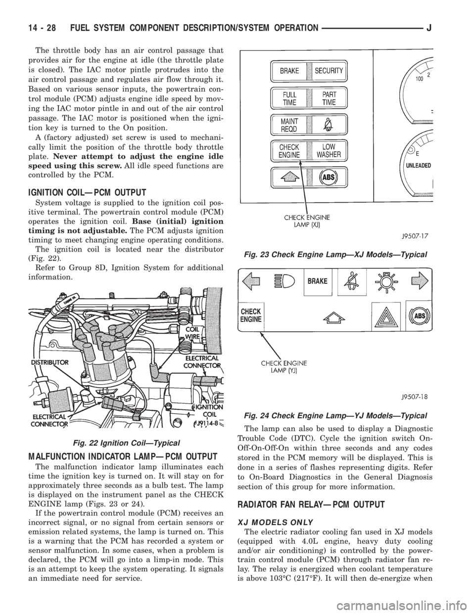
The ignition coil is located near the distributor
(Fig. 22).
Refer to Group 8D, Ignition System for additional
information.
MALFUNCTION INDICATOR LAMPÐPCM OUTPUT
The malfunction indicator lamp illuminates each
time the ignition key is turned on. It will stay on for
approximately three seconds as a bulb test. The lamp
is displayed on the instrument panel as the CHECK
ENGINE lamp (Figs. 23 or 24).
If the powertrain control module (PCM) receives an
incorrect signal, or no signal from certain sensors or
emission related systems, the lamp is turned on. This
is a warning that the PCM has recorded a system or
sensor malfunction. In some cases, when a problem is
declared, the PCM will go into a limp-in mode. This
is an attempt to keep the system operating. It signals
an immediate need for service.The lamp can also be used to display a Diagnostic
Trouble Code (DTC). Cycle the ignition switch On-
Off-On-Off-On within three seconds and any codes
stored in the PCM memory will be displayed. This is
done in a series of flashes representing digits. Refer
to On-Board Diagnostics in the General Diagnosis
section of this group for more information.
RADIATOR FAN RELAYÐPCM OUTPUT
XJ MODELS ONLY
The electric radiator cooling fan used in XJ models
(equipped with 4.0L engine, heavy duty cooling
and/or air conditioning) is controlled by the power-
train control module (PCM) through radiator fan re-
lay. The relay is energized when coolant temperature
is above 103ÉC (217ÉF). It will then de-energize when
Fig. 22 Ignition CoilÐTypical
Fig. 23 Check Engine LampÐXJ ModelsÐTypical
Fig. 24 Check Engine LampÐYJ ModelsÐTypical
14 - 28 FUEL SYSTEM COMPONENT DESCRIPTION/SYSTEM OPERATIONJ