1995 JEEP XJ ECO mode
[x] Cancel search: ECO modePage 188 of 2158

During normal braking, the master cylinder, power
booster and wheel brake units all function as they
would in a vehicle without ABS. The HCU compo-
nents are not activated.
ABS OPERATION IN ANTILOCK BRAKING MODE
The purpose of the antilock system is to prevent
wheel lockup during periods of high wheel slip. Pre-
venting lockup helps maintain vehicle braking action
and steering control.
The antilock ECU activates the system whenever
sensor signals indicate periods of high wheel slip.
High wheel slip can be described as the point where
wheel rotation begins approaching zero (or lockup)
during braking. Periods of high wheel slip may occur
when brake stops involve high pedal pressure and
rate of deceleration.
The antilock system prevents lockup during high
slip conditions by modulating fluid apply pressure to
the wheel brake units.
Brake fluid apply pressure is modulated according
to wheel speed, degree of slip and rate of decelera-
tion. A sensor at each wheel converts wheel speed
into electrical signals. These signals are transmitted
to the ECU for processing and determination of
wheel slip and deceleration rate.
The ABS system has three fluid pressure control
channels. The front brakes are controlled separately
and the rear brakes in tandem (Fig. 1). A speed sen-
sor input signal indicating a high slip condition acti-
vates the ECU antilock program.
Two solenoid valves are used in each antilock con-
trol channel. The valves are all located within the
HCU valve body and work in pairs to either increase,
hold, or decrease apply pressure as needed in the in-
dividual control channels.
The solenoid valves are not static during antilock
braking. They are cycled continuously to modulate
pressure. Solenoid cycle time in antilock mode can be
measured in milliseconds.
HCU OPERATION
Normal Braking
During normal braking, the HCU solenoid valves
and pump are not activated. The master cylinder and
power booster operate the same as a vehicle without
an ABS brake system.
Antilock Pressure Modulation
Solenoid valve pressure modulation occurs in three
stages which are: pressure increase, pressure hold,
and pressure decrease. The valves are all contained
in the valve body portion of the HCU.
Pressure Decrease
The outlet valve is opened and the inlet valve is
closed during the pressure decrease cycle (Fig. 6).A pressure decrease cycle is initiated when speed
sensor signals indicate high wheel slip at one or
more wheels. At this point, the ECU opens the outlet
valve, which also opens the return circuit to the ac-
cumulators. Fluid pressure is allowed to bleed off (de-
crease) as needed to prevent wheel lock.
Once the period of high wheel slip has ended, the
ECU closes the outlet valve and begins a pressure in-
crease or hold cycle as needed.
Pressure Hold
Both solenoid valves are closed in the pressure hold
cycle (Fig. 7). Fluid apply pressure in the control
channel is maintained at a constant rate. The ECU
maintains the hold cycle until sensor inputs indicate
a pressure change is necessary.
Pressure Increase
The inlet valve is open and the outlet valve is
closed during the pressure increase cycle (Fig. 8). The
pressure increase cycle is used to counteract unequal
wheel speeds. This cycle controls re-application of
fluid apply pressure due to changing road surfaces or
wheel speed.
Fig. 6 Pressure Decrease Cycle
5 - 36 ABS OPERATION AND SERVICEJ
Page 189 of 2158

WHEEL SPEED SENSOR OPERATION
Wheel speed input signals are generated by a sen-
sor and tone ring at each wheel. The sensors, which
are connected directly to the ECU, are mounted on
brackets attached to the front steering knuckles and
rear brake support plates.
The sensor triggering devices are the tone rings
which are similar in appearance to gears. The tone
rings are located on the outboard end of each front/rear axle shaft. The speed sensors generate a signal
whenever a tone ring tooth rotates past the sensor
pickup face.
The wheel speed sensors provide the input signal
to the ECU. If input signals indicate ABS mode brak-
ing, the ECU causes the HCU solenoids to decrease,
hold, or increase fluid apply pressure as needed.
The HCU solenoid valves are activated only when
wheel speed input signals indicate that a wheel is
approaching a high slip, or lockup condition. At this
point, the ECU will cycle the appropriate wheel con-
trol channel solenoid valves to prevent lockup.
The wheel sensors provide speed signals whenever
the vehicle wheels are rotating. The ECU examines
these signals for degree of deceleration and wheel
slip. If signals indicate normal braking, the solenoid
valves are not activated. However, when incoming
signals indicate the approach of wheel slip, or lockup,
the ECU cycles the solenoid valves as needed.
ACCELERATION SWITCH OPERATION
The ECU monitors the acceleration switch at all
times. The switch assembly contains three mercury
switches that monitor vehicle ride height and decel-
eration rates (G-force). Sudden, rapid changes in ve-
hicle and wheel deceleration rate, triggers the switch
sending a signal to the ECU. The switch assembly
provides three deceleration rates; two for forward
braking and one for rearward braking.
ECU OPERATION
The antilock ECU controls all phases of antilock
operation. It monitors and processes input signals
from the system sensors.
It is the ECU that activates the solenoid valves to
modulate apply pressure during antilock braking.
The ECU program is able to determine which wheel
control channel requires modulation and which fluid
pressure modulation cycle to use. The ECU cycles the
solenoid valves through the pressure decrease, hold
and increase phases.
ABS COMPONENT SERVICEABILITY
The ECU, acceleration sensor, wheel sensors, and
wire harnesses are serviced as assemblies only. The
axle shaft tone wheels are also not serviceable. If a
tone wheel becomes damaged, it will be necessary to
replace the axle shaft, or disc brake rotor and hub
assembly.
SPEED SENSOR AIR GAP
Front sensor air gap is fixed and not adjustable.
Only rear sensor air gap is adjustable.
Although front air gap is not adjustable, it can be
checked if diagnosis indicates this is necessary. Front
Fig. 7 Pressure Hold Cycle
Fig. 8 Pressure Increase Cycle
JABS OPERATION AND SERVICE 5 - 37
Page 213 of 2158
secondary brakeshoes move the shoes directly into
contact with the drum braking surface. The actuating
levers are interconnected by a system of cables and a
tensioner mechanism. The tensioner mechanism con-
trols parking brake adjustment.
A parking brake switch is used on all models. It is
mounted on the parking brake lever or foot pedal and
is actuated by movement of the lever/pedal. The
switch, which is in circuit with the red warning light
in the dash, will illuminate the warning light when-
ever the parking brakes are applied.
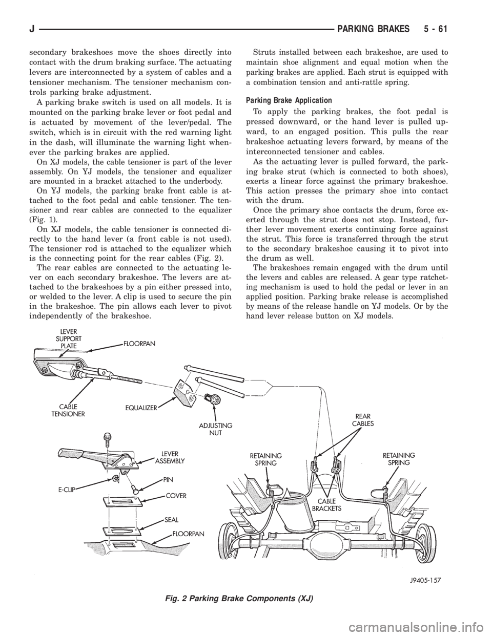
On XJ models, the cable tensioner is part of the lever
assembly. On YJ models, the tensioner and equalizer
are mounted in a bracket attached to the underbody.
On YJ models, the parking brake front cable is at-
tached to the foot pedal and cable tensioner. The ten-
sioner and rear cables are connected to the equalizer
(Fig. 1).
On XJ models, the cable tensioner is connected di-
rectly to the hand lever (a front cable is not used).
The tensioner rod is attached to the equalizer which
is the connecting point for the rear cables (Fig. 2).
The rear cables are connected to the actuating le-
ver on each secondary brakeshoe. The levers are at-
tached to the brakeshoes by a pin either pressed into,
or welded to the lever. A clip is used to secure the pin
in the brakeshoe. The pin allows each lever to pivot
independently of the brakeshoe.
Struts installed between each brakeshoe, are used to
maintain shoe alignment and equal motion when the
parking brakes are applied. Each strut is equipped with
a combination tension and anti-rattle spring.
Parking Brake Application
To apply the parking brakes, the foot pedal is
pressed downward, or the hand lever is pulled up-
ward, to an engaged position. This pulls the rear
brakeshoe actuating levers forward, by means of the
interconnected tensioner and cables.
As the actuating lever is pulled forward, the park-
ing brake strut (which is connected to both shoes),
exerts a linear force against the primary brakeshoe.
This action presses the primary shoe into contact
with the drum.
Once the primary shoe contacts the drum, force ex-
erted through the strut does not stop. Instead, fur-
ther lever movement exerts continuing force against
the strut. This force is transferred through the strut
to the secondary brakeshoe causing it to pivot into
the drum as well.
The brakeshoes remain engaged with the drum until
the levers and cables are released. A gear type ratchet-
ing mechanism is used to hold the pedal or lever in an
applied position. Parking brake release is accomplished
by means of the release handle on YJ models. Or by the
hand lever release button on XJ models.
Fig. 2 Parking Brake Components (XJ)
JPARKING BRAKES 5 - 61
Page 220 of 2158
PARKING BRAKE REAR CABLE REPLACEMENT (YJ)
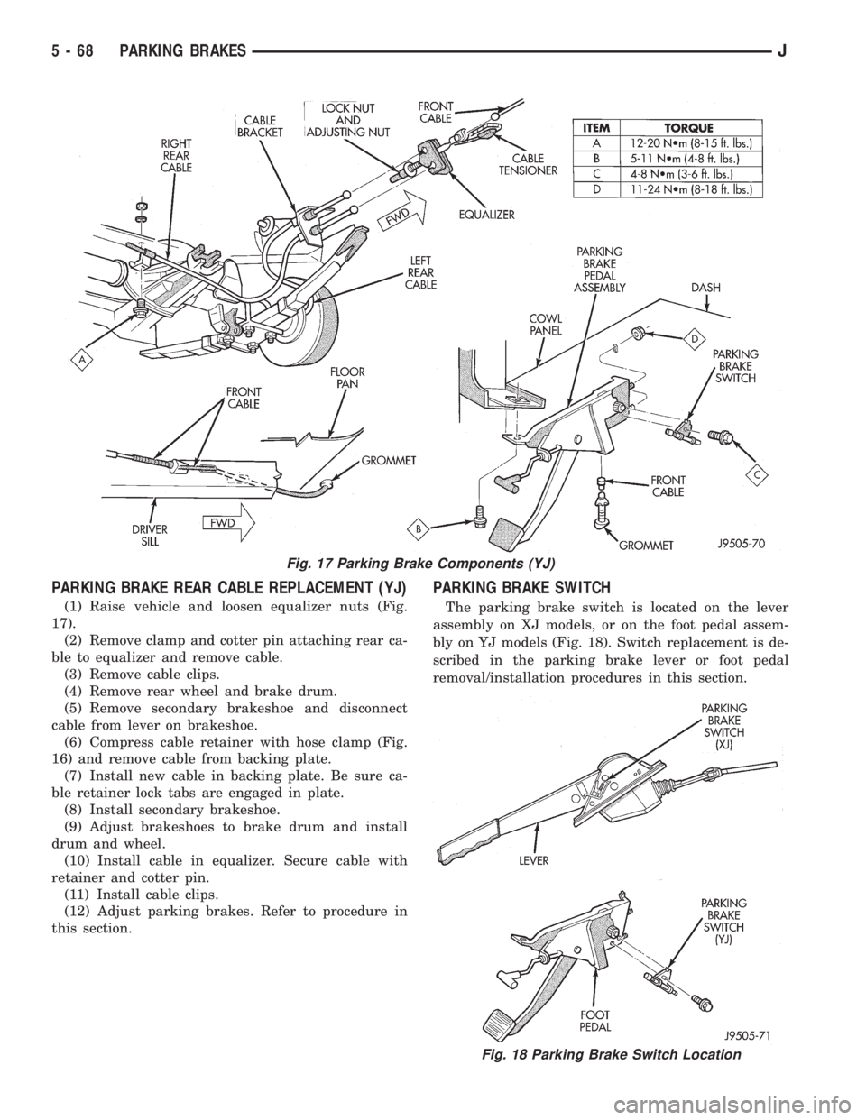
(1) Raise vehicle and loosen equalizer nuts (Fig.
17).
(2) Remove clamp and cotter pin attaching rear ca-
ble to equalizer and remove cable.
(3) Remove cable clips.
(4) Remove rear wheel and brake drum.
(5) Remove secondary brakeshoe and disconnect
cable from lever on brakeshoe.
(6) Compress cable retainer with hose clamp (Fig.
16) and remove cable from backing plate.
(7) Install new cable in backing plate. Be sure ca-
ble retainer lock tabs are engaged in plate.
(8) Install secondary brakeshoe.
(9) Adjust brakeshoes to brake drum and install
drum and wheel.
(10) Install cable in equalizer. Secure cable with
retainer and cotter pin.
(11) Install cable clips.
(12) Adjust parking brakes. Refer to procedure in
this section.
PARKING BRAKE SWITCH
The parking brake switch is located on the lever
assembly on XJ models, or on the foot pedal assem-
bly on YJ models (Fig. 18). Switch replacement is de-
scribed in the parking brake lever or foot pedal
removal/installation procedures in this section.
Fig. 17 Parking Brake Components (YJ)
Fig. 18 Parking Brake Switch Location
5 - 68 PARKING BRAKESJ
Page 235 of 2158
(8) Install transmission. Refer to Group 21 for pro-
cedure.
CLUTCH HOUSING REPLACEMENT
The clutch housing is removable and can be re-
placed when the transmission is out of the vehicle.
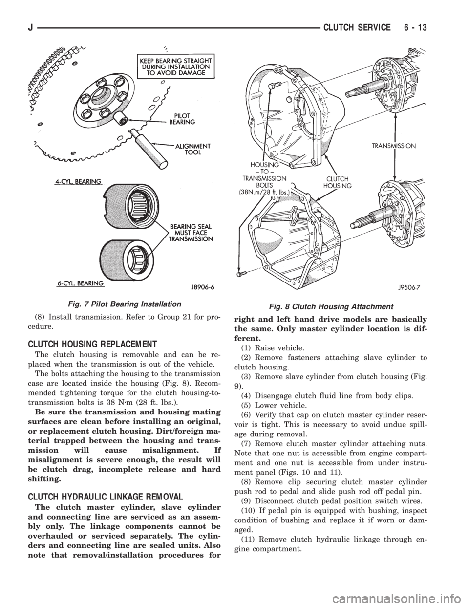
The bolts attaching the housing to the transmission
case are located inside the housing (Fig. 8). Recom-
mended tightening torque for the clutch housing-to-
transmission bolts is 38 Nzm (28 ft. lbs.).
Be sure the transmission and housing mating
surfaces are clean before installing an original,
or replacement clutch housing. Dirt/foreign ma-
terial trapped between the housing and trans-
mission will cause misalignment. If
misalignment is severe enough, the result will
be clutch drag, incomplete release and hard
shifting.
CLUTCH HYDRAULIC LINKAGE REMOVAL
The clutch master cylinder, slave cylinder
and connecting line are serviced as an assem-
bly only. The linkage components cannot be
overhauled or serviced separately. The cylin-
ders and connecting line are sealed units. Also
note that removal/installation procedures forright and left hand drive models are basically
the same. Only master cylinder location is dif-
ferent.
(1) Raise vehicle.
(2) Remove fasteners attaching slave cylinder to
clutch housing.
(3) Remove slave cylinder from clutch housing (Fig.
9).
(4) Disengage clutch fluid line from body clips.
(5) Lower vehicle.
(6) Verify that cap on clutch master cylinder reser-
voir is tight. This is necessary to avoid undue spill-
age during removal.
(7) Remove clutch master cylinder attaching nuts.
Note that one nut is accessible from engine compart-
ment and one nut is accessible from under instru-
ment panel (Figs. 10 and 11).
(8) Remove clip securing clutch master cylinder
push rod to pedal and slide push rod off pedal pin.
(9) Disconnect clutch pedal position switch wires.
(10) If pedal pin is equipped with bushing, inspect
condition of bushing and replace it if worn or dam-
aged.
(11) Remove clutch hydraulic linkage through en-
gine compartment.
Fig. 8 Clutch Housing AttachmentFig. 7 Pilot Bearing Installation
JCLUTCH SERVICE 6 - 13
Page 243 of 2158
DIAGNOSIS
INDEX
page page
DRB Scan Tool............................ 5
On-Board Diagnostics (OBD).................. 4Preliminary Checks......................... 5
ON-BOARD DIAGNOSTICS (OBD)
FOR CERTAIN COOLING SYSTEM
COMPONENTS
The powertrain control module (PCM) has been
programmed to monitor the certain following cooling
system components:
²If the engine has remained cool for too long a pe-
riod, such as with a stuck open thermostat, a Diag-
nostic Trouble Code (DTC) number 17 can be
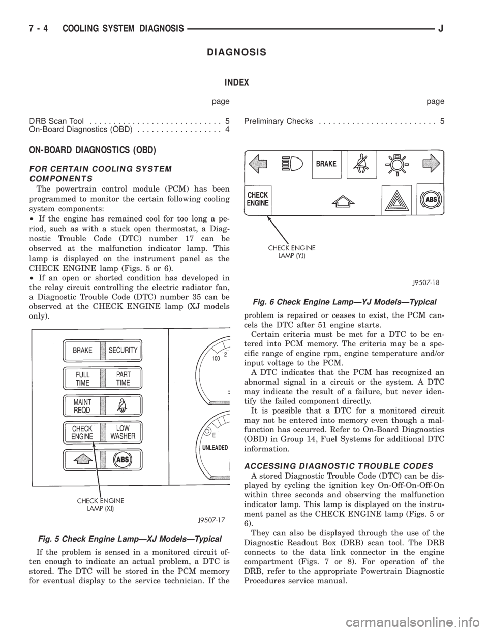
observed at the malfunction indicator lamp. This
lamp is displayed on the instrument panel as the
CHECK ENGINE lamp (Figs. 5 or 6).
²If an open or shorted condition has developed in
the relay circuit controlling the electric radiator fan,
a Diagnostic Trouble Code (DTC) number 35 can be
observed at the CHECK ENGINE lamp (XJ models
only).
If the problem is sensed in a monitored circuit of-
ten enough to indicate an actual problem, a DTC is
stored. The DTC will be stored in the PCM memory
for eventual display to the service technician. If theproblem is repaired or ceases to exist, the PCM can-
cels the DTC after 51 engine starts.
Certain criteria must be met for a DTC to be en-
tered into PCM memory. The criteria may be a spe-
cific range of engine rpm, engine temperature and/or
input voltage to the PCM.
A DTC indicates that the PCM has recognized an
abnormal signal in a circuit or the system. A DTC
may indicate the result of a failure, but never iden-
tify the failed component directly.
It is possible that a DTC for a monitored circuit
may not be entered into memory even though a mal-
function has occurred. Refer to On-Board Diagnostics
(OBD) in Group 14, Fuel Systems for additional DTC
information.
ACCESSING DIAGNOSTIC TROUBLE CODES
A stored Diagnostic Trouble Code (DTC) can be dis-
played by cycling the ignition key On-Off-On-Off-On
within three seconds and observing the malfunction
indicator lamp. This lamp is displayed on the instru-
ment panel as the CHECK ENGINE lamp (Figs. 5 or
6).
They can also be displayed through the use of the
Diagnostic Readout Box (DRB) scan tool. The DRB
connects to the data link connector in the engine
compartment (Figs. 7 or 8). For operation of the
DRB, refer to the appropriate Powertrain Diagnostic
Procedures service manual.
Fig. 5 Check Engine LampÐXJ ModelsÐTypical
Fig. 6 Check Engine LampÐYJ ModelsÐTypical
7 - 4 COOLING SYSTEM DIAGNOSISJ
Page 244 of 2158
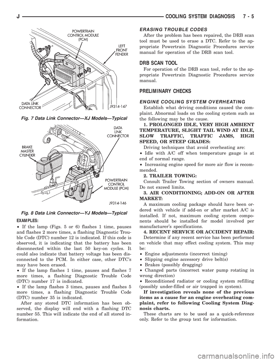
EXAMPLES:
²If the lamp (Figs. 5 or 6) flashes 1 time, pauses
and flashes 2 more times, a flashing Diagnostic Trou-
ble Code (DTC) number 12 is indicated. If this code is
observed, it is indicating that the battery has been
disconnected within the last 50 key-on cycles. It
could also indicate that battery voltage has been dis-
connected to the PCM. In either case, other DTC's
may have been erased.
²If the lamp flashes 1 time, pauses and flashes 7
more times, a flashing Diagnostic Trouble Code
(DTC) number 17 is indicated.
²If the lamp flashes 3 times, pauses and flashes 5
more times, a flashing Diagnostic Trouble Code
(DTC) number 35 is indicated.
After any stored DTC information has been ob-
served, the display will end with a flashing DTC
number 55. This will indicate the end of all stored in-
formation.
ERASING TROUBLE CODES
After the problem has been repaired, the DRB scan
tool must be used to erase a DTC. Refer to the ap-
propriate Powertrain Diagnostic Procedures service
manual for operation of the DRB scan tool.
DRB SCAN TOOL
For operation of the DRB scan tool, refer to the ap-
propriate Powertrain Diagnostic Procedures service
manual.
PRELIMINARY CHECKS
ENGINE COOLING SYSTEM OVERHEATING
Establish what driving conditions caused the com-
plaint. Abnormal loads on the cooling system such as
the following may be the cause.
1. PROLONGED IDLE, VERY HIGH AMBIENT
TEMPERATURE, SLIGHT TAIL WIND AT IDLE,
SLOW TRAFFIC, TRAFFIC JAMS, HIGH
SPEED, OR STEEP GRADES:
Driving techniques that avoid overheating are:
²Idle with A/C off when temperature gauge is at
end of normal range.
²Increasing engine speed for more air flow is recom-
mended.
2. TRAILER TOWING:
Consult Trailer Towing section of owners manual.
Do not exceed limits.
3. AIR CONDITIONING; ADD-ON OR AFTER
MARKET:
A maximum cooling package should have been or-
dered with vehicle if add-on or after market A/C is
installed. If not, maximum cooling system compo-
nents should be installed for model involved per
manufacturer's specifications.
4. RECENT SERVICE OR ACCIDENT REPAIR:
Determine if any recent service has been performed
on vehicle that may effect cooling system. This may
be:
²Engine adjustments (incorrect timing)
²Slipping engine accessory drive belt(s)
²Brakes (possibly dragging)
²Changed parts (incorrect water pump rotating in
wrong direction)
²Reconditioned radiator or cooling system refilling
(possibly under-filled or air trapped in system).
If investigation reveals none of the previous
items as a cause for an engine overheating com-
plaint, refer to following Cooling System Diag-
nosis charts.
These charts are to be used as a quick-reference
only. Refer to the group text for information.
Fig. 7 Data Link ConnectorÐXJ ModelsÐTypical
Fig. 8 Data Link ConnectorÐYJ ModelsÐTypical
JCOOLING SYSTEM DIAGNOSIS 7 - 5
Page 257 of 2158
temperature, coolant is allowed to flow to the radia-
tor. This provides quick engine warmup and overall
temperature control.
An arrow plus the wordUPis stamped on the
front flange next to the air bleed. The wordsTO
RADare stamped on one arm of the thermostat.
They indicate the proper installed position.
The same thermostat is used for winter and sum-
mer seasons. An engine should not be operated with-
out a thermostat, except for servicing or testing.
Operating without a thermostat causes other prob-
lems. These are: longer engine warmup time, unreli-
able warmup performance, increased exhaust
emissions and crankcase condensation. This conden-
sation can result in sludge formation.
CAUTION: Do not operate an engine without a ther-
mostat, except for servicing or testing.
ON-BOARD DIAGNOSTICS
XJ and YJ models are equipped with On-Board Di-
agnostics for certain cooling system components. Re-
fer to On-Board Diagnostics (OBD) in the Diagnosis
section of this group for additional information. If the
powertrain control module (PCM) detects low engine
coolant temperature, it will record a Diagnostic Trou-
ble Code (DTC) in the PCM memory. The DTC num-
ber for low coolant temperature is 17. Do not change
a thermostat for lack of heat as indicated by the in-
strument panel gauge or heater performance unless a
DTC number 17 is present. Refer to the Diagnosis
section of this group for other probable causes. For
other DTC numbers, refer to On-Board Diagnostics
in the General Diagnosis section of Group 14, Fuel
Systems.
The DTC can also be accessed through the DRB
scan tool. Refer to the appropriate Powertrain Diag-
nostic Procedures manual for diagnostic information
and operation of the DRB scan tool.
REMOVAL
WARNING: DO NOT LOOSEN THE RADIATOR
DRAINCOCK WITH THE SYSTEM HOT AND PRES-
SURIZED. SERIOUS BURNS FROM THE COOLANT
CAN OCCUR.
DO NOT WASTE reusable coolant. If the solution
is clean, drain the coolant into a clean container for
reuse.
(1) Drain the coolant from the radiator until the
level is below the thermostat housing.
WARNING: CONSTANT TENSION HOSE CLAMPS
ARE USED ON MOST COOLING SYSTEM HOSES.
WHEN REMOVING OR INSTALLING, USE ONLY
TOOLS DESIGNED FOR SERVICING THIS TYPE OF
CLAMP, SUCH AS SPECIAL CLAMP TOOL (NUMBER
6094) (FIG. 15). SNAP-ON CLAMP TOOL (NUMBER
HPC-20) MAY BE USED FOR LARGER CLAMPS. AL-
WAYS WEAR SAFETY GLASSES WHEN SERVICING
CONSTANT TENSION CLAMPS.
CAUTION: A number or letter is stamped into the
tongue of constant tension clamps (Fig. 16). If re-
placement is necessary, use only an original equip-
ment clamp with matching number or letter.
(2) Remove radiator upper hose and heater hose at
thermostat housing.
(3) Disconnect wiring connector at engine coolant
temperature sensor.
(4) Remove thermostat housing mounting bolts,
thermostat housing, gasket and thermostat (Fig. 17).
Discard old gasket.
(5) Clean the gasket mating surfaces.
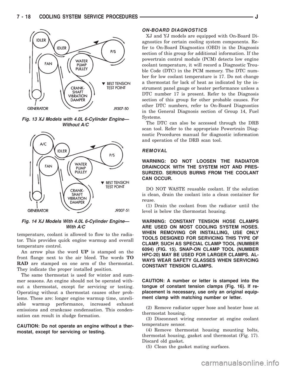
Fig. 13 XJ Models with 4.0L 6-Cylinder EngineÐ
Without A/C
Fig. 14 XJ Models With 4.0L 6-Cylinder EngineÐ
With A/C
7 - 18 COOLING SYSTEM SERVICE PROCEDURESJ