1995 JEEP XJ clutch
[x] Cancel search: clutchPage 3 of 2158
GROUP TAB LOCATOR
Introduction
0Lubrication and Maintenance
2Front Suspension and Axle
3Rear Suspension and Axles
5Brakes
6Clutch
7Cooling System
8Electrical
9Engines
11Exhaust System and Intake Manifold
13Frame and Bumpers
14Fuel System
16Propeller Shafts
19Steering
21Transmission and Transfer Cases
22Wheels and Tires
23Body Components
24Heating and Air Conditioning
25Emission Control Systems
Index
Service Manual Comment Forms (Rear of Manual)
Page 41 of 2158

DRIVETRAIN
INDEX
page page
Automatic Transmission.................... 23
Clutch and Brake Pedal Bushings............. 22
Clutch Master Cylinder..................... 22
Drive Shafts............................. 26Front and Rear Axles...................... 24
Manual Transmission...................... 22
Rubber and Plastic Hoses/Tubing............. 26
Transfer Case (4WD Vehicles)................ 24
CLUTCH AND BRAKE PEDAL BUSHINGS
If the clutch and brake pedal mechanism squeaks,
the pivot bushings should be lubricated. Use Mopar
Multi-Purpose Lubricant, or an equivalent. Refer to
Group 5, Brakes for location of bushings.
CLUTCH MASTER CYLINDER
LEVEL INSPECTION
WARNING: DO NOT ALLOW PETROLEUM OR WA-
TER BASE LIQUIDS TO CONTAMINATE CLUTCH
FLUID, SEAL DAMAGE AND CLUTCH FAILURE CAN
RESULT.
The clutch reservoir level should be inspected when
other underhood service is performed. (Fig. 1)
The fluid level is determined by its height in rela-
tion to the level indicator ring (Fig. 2) located inside
the reservoir. Add fluid until the height is level with
the indicator ring.
FLUID SPECIFICATION
Use Mopar, Brake And Hydraulic Clutch Fluid or
equivalent. Use only brake fluid conforming to DOT
3, Federal, Department of Transportation specifica-
tion. To avoid fluid contamination, use fluid from a
properly sealed container.CAUTION: Never use reclaimed brake fluid or fluid
from an unsealed container. In addition, do not use
fluid from a container that has been opened and al-
lowed to stand for an extended length of time.
Moisture in the air can be absorbed by the fluid,
which causes dilution with loss of effectiveness.
MANUAL TRANSMISSION
The manual transmission should be inspected for
oil leaks and proper oil level when other under vehi-
cle service is performed.
LUBRICANT SPECIFICATION
When it becomes necessary to add to or change the
lube oil in a Jeep manual transmission, use SAE
75W-90, API Quality Grade GL-5 gear lubricant.
LUBRICANT LEVEL
The fill-hole plug for all manual transmissions is
located on the right side of the case (Fig. 3). Deter-
mine the lubricant level according to the following
procedure.
(1) Remove the fill-hole plug (Fig. 3) from the
transmission. The lube oil should be level with the
bottom edge of the fill hole. The level can be slightly
below the bottom edge of the fill hole if the lube oil is
cold.
Fig. 1 Clutch Reservoir LocationÐTypical
Fig. 2 Hydraulic Clutch Fluid LevelÐTypical
0 - 22 LUBRICATION AND MAINTENANCEJ
Page 71 of 2158
Axle shaft bearings produce noise and vibration
when worn or damaged. The noise generally changes
when the bearings are loaded. Road test the vehicle.
Turn the vehicle sharply to the left and to the right.
This will load the bearings and change the noise
level. Where axle bearing damage is slight, the noise
is usually not noticeable at speeds above 30 mph.
LOW SPEED KNOCK
Low speed knock is generally caused by a worn U-
joint or by worn side-gear thrust washers. A worn
pinion gear shaft bore will also cause low speed
knock.
VIBRATION
Vibration at the rear of the vehicle is usually
caused by a:
²Damaged drive shaft
²Missing drive shaft balance weight
²Worn, out-of-balance wheels
²Loose wheel lug nuts
²Worn U-joint
²Loose spring U-bolts
²Loose/broken springs
²Damaged axle shaft bearings
²Loose pinion gear nut
²Excessive pinion yoke run out²Bent axle shaft
Check for loose or damaged front-end components
or engine/transmission mounts. These components
can contribute to what appears to be a rear-end vi-
bration. Do not overlook engine accessories, brackets
and drive belts.
All driveline components should be examined be-
fore starting any repair.
Refer to Group 22ÐTires And Wheels for addi-
tional information involving vibration diagnosis.
DRIVELINE SNAP
A snap or clunk noise when the vehicle is shifted
into gear (or the clutch engaged), can be caused by:
²High engine idle speed
²Loose engine/transmission/transfer case mounts
²Worn U-joints
²Loose spring mounts
²Loose pinion gear nut and yoke
²Excessive ring gear backlash
²Excessive differential side gear-to-case clearance
The source of a snap or a clunk noise can be deter-
mined with the assistance of a helper. Raise the ve-
hicle on a hoist with the wheels free to rotate.
Instruct the helper to shift the transmission into
gear. Listen for the noise, a mechanics stethoscope is
helpful in isolating the source of a noise.
JFRONT SUSPENSION AND AXLE 2 - 19
Page 111 of 2158
This will load the bearings and change the noise
level. Where axle bearing damage is slight, the noise
is usually not noticeable at speeds above 30 mph.
LOW SPEED KNOCK
Low speed knock is generally caused by a worn
U-joint or by worn side-gear thrust washers. A worn
pinion gear shaft bore will also cause low speed knock.
VIBRATION
Vibration at the rear of the vehicle is usually
caused by a:
²Damaged drive shaft
²Missing drive shaft balance weight
²Worn, out-of-balance wheels
²Loose wheel lug nuts
²Worn U-joint
²Loose spring U-bolts
²Loose/broken springs
²Damaged axle shaft bearings
²Loose pinion gear nut
²Excessive pinion yoke run out
²Bent axle shaft
Check for loose or damaged front-end components
or engine/transmission mounts. These components
can contribute to what appears to be a rear-end vi-
bration. Do not overlook engine accessories, brackets
and drive belts.
All driveline components should be examined be-
fore starting any repair.
Refer to Group 22, Wheels and Tires for additional
information.
DRIVELINE SNAP
A snap or clunk noise when the vehicle is shifted
into gear (or the clutch engaged), can be caused by:
²High engine idle speed
²Loose engine/transmission/transfer case mounts
²Worn U-joints
²Loose spring mounts
²Loose pinion gear nut and yoke
²Excessive ring gear backlash
²Excessive side gear\ase clearance
The source of a snap or a clunk noise can be deter-
mined with the assistance of a helper. Raise the ve-
hicle on a hoist with the wheels free to rotate.
Instruct the helper to shift the transmission into
gear. Listen for the noise, a mechanics stethoscope is
helpful in isolating the source of a noise.
REAR AXLE ALIGNMENT
MEASUREMENT
The following procedure can be used to determine
if abnormal rear tire tread wear is the result of a
bent or deformed rear axle shaft.
(1) Raise both rear wheels off the surface with a
frame contact hoist.
(2) Attach a one-inch long piece of masking tape at
the center of each tire tread for use as reference marks.
(3) Rotate the rear wheels until both reference
marks face the front of the vehicle. Measure the dis-
tance between the outside edges of the two pieces of
tape. Record this measurement as the front of tire
(FTR) measurement.
(4) Rotate the rear wheels until both reference
marks face the rear of the vehicle. Measure the dis-
tance between the outside edges of the two pieces of
tape. Record this measurement as the rear of tire
(RTR) measurement.
(5) Subtract the (RTR) measurement from the
(FTR) measurement to obtain the amount of wheel
toe. The acceptable rear wheel toe-in position is 1/16
inch (1.6 mm) to 3/16 inch (4.8 mm) toe-out.
(6) Rotate the rear wheels until the reference
marks are facing downward. Measure the distance
between the outside edges of the two pieces of tape.
Record this measurement as the bottom of tire (BTR)
measurement.
(7) Average the (FTR) and the (RTR) distance mea-
surements. Subtract the (BTR) measurement from
this average distance to obtain the camber. The ac-
ceptable amount of camber is 1/16 inch to 3/32 inch
(1.6 to 2.4 mm).
(FTR + RTR) DIVIDED BY 2 (TWO) MINUS
BTR EQUALS CAMBER
If the (BTR) distance measurement is less
than the average FTR and RTR distance mea-
surement, the camber will be positive(+).If
the (BTR) distance measurement is greater
than the average FTR and RTR distance, the
camber will be negative(-).
If the toe position or camber is not acceptable, a bent
or deformed rear axle shaft is most likely the cause.
LIMITED SLIP DIFFERENTIAL
Under normal traction conditions, engine torque is di-
vided evenly. With low-traction surfaces, engine torque
is transferred to the wheel with the most tire traction.
When diagnosing a limited-slip differential the wheel
with the least traction can continue spinning.
The most common problem is a chatter noise when
turning corners. Check for incorrect or contaminated
lubricant. Replace the gear lubricant if necessary.
²With Trac-LokŸ differentials add a container of
MOPAR Trac-Lok Lubricant.
This will correct the condition in most instances. If
the chatter persists, clutch damage could have oc-
curred.
After changing the lubricant, drive the vehicle and
make 10 to 12 slow, figure-eight turns. This maneu-
ver will pump lubricant through the clutches.
3 - 10 REAR SUSPENSION AND AXLESJ
Page 115 of 2158
CAUTION: Overfilling the differential can result in
lubricant foaming and overheating.
Trac-Lok Differentials; A container of Trac-Lok lu-
bricant (friction modifier) should be added after re-
pair service or a lubricant change.
(9) Install the fill hole plug and lower the vehicle.
LIMITED SLIP DIFFERENTIAL vehicles should
be road tested by making 10 to 12 slow figure-eight
turns. This maneuver will pump the lubricant
through the clutch discs to eliminate a possible chat-
ter noise complaint.
DRIVE AXLE ASSEMBLY REPLACEMENTÐXJ
VEHICLES
REMOVAL
(1) Raise the vehicle and position support stands
under the frame rails slightly in front the springs.
(2) Remove the rear wheels.
(3) Mark the drive shaft yoke and axle pinion yoke
for alignment reference. Disconnect the drive shaft
from the axle.
(4) Disconnect the axle vent hose.
(5) Disconnect the parking brake cables at the
equalizer or backing plate.
(6) Disconnect the shock absorbers from the axle
brackets.
(7) Disconnect the brake hose at the axle junction
block.Do not disconnect the wheel cylinder tub-
ing fittings.
(8) If equipped, disconnect ABS wiring connections
at the axle.(9) Support the axle with a hydraulic jack under
the differential.
(10) Remove the spring U-bolts from the plate
brackets.
(11) Lower the jack enough to remove the axle.
INSTALLATION
CAUTION: Suspension components with rubber
bushings should be tightened with the vehicle at
normal height. It is important to have the springs
supporting the weight of the vehicle when the fas-
teners are torqued. If springs are not at their normal
ride position, vehicle ride comfort could be affected
and premature bushing wear may occur. Rubber
bushings must never be lubricated.
(1) Support the axle on a hydraulic jack under the
differential. Position the axle under the vehicle.
(2) Raise the axle and align the spring center bolts
with the locating holes in the axle pads and plate
brackets.
(3) Install the spring U-bolts through the plate
brackets and tighten to 70 Nzm (52 ft. lbs.) torque.
(4) Install ABS wiring connections (if equipped) at
the axle.
(5) Connect the brake hose at the axle junction
block.
(6) Install the shock absorbers to the axle brackets
and tighten to 62 Nzm (46 ft. lbs.) torque.
(7) Connect the parking brake cables at the equal-
izer or backing plate.
(8) Connect the vent hose to the tube fitting.
(9) Align the reference marks and connect the
drive shaft to the axle yoke. Tighten the U-joint
clamp bolts to 19 Nzm (14 ft. lbs.) torque.
(10) Check differential lubricant and add if neces-
sary.
(11) Install the wheel and tire.
(12) Bleed the brakes.
(13) Remove the supports and lower the vehicle.
DRIVE AXLE ASSEMBLY REPLACEMENTÐYJ
VEHICLES
REMOVAL
(1) Raise the vehicle and position support stands
under the frame rails slightly in front the springs.
(2) Remove the rear wheels.
(3) Mark the drive shaft yoke and axle pinion yoke
for alignment reference. Disconnect the drive shaft
from the axle.
(4) Disconnect the axle vent hose.
(5) Disconnect the parking brake cables at the
equalizer or backing plate.
(6) Disconnect the shock absorbers from the plate
brackets.
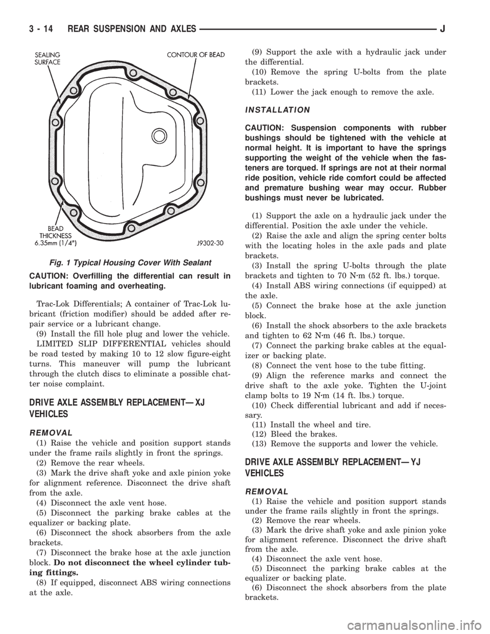
Fig. 1 Typical Housing Cover With Sealant
3 - 14 REAR SUSPENSION AND AXLESJ
Page 146 of 2158
TRAC-LOK DIFFERENTIAL
OPERATION
In a conventional differential, the torque applied to
the ring gear is transmitted to the axle shafts through
the differential gears. During normal operation, the
torque transmitted to each wheel is equal at all times.
However, if one wheel spins, the opposite wheel will
generate only as much torque as the spinning wheel.
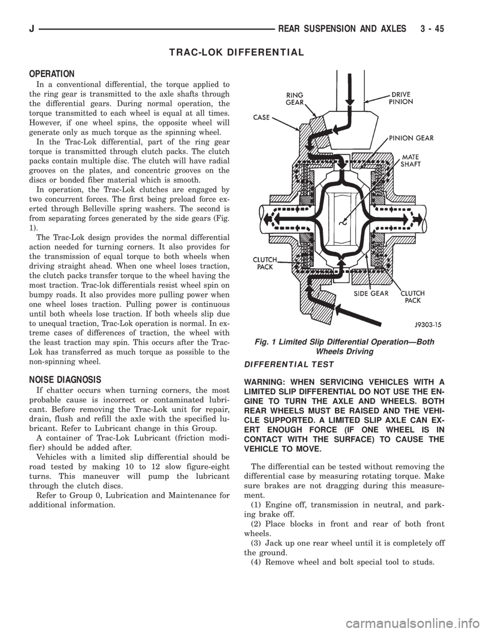
In the Trac-Lok differential, part of the ring gear
torque is transmitted through clutch packs. The clutch
packs contain multiple disc. The clutch will have radial
grooves on the plates, and concentric grooves on the
discs or bonded fiber material which is smooth.
In operation, the Trac-Lok clutches are engaged by
two concurrent forces. The first being preload force ex-
erted through Belleville spring washers. The second is
from separating forces generated by the side gears (Fig.
1).
The Trac-Lok design provides the normal differential
action needed for turning corners. It also provides for
the transmission of equal torque to both wheels when
driving straight ahead. When one wheel loses traction,
the clutch packs transfer torque to the wheel having the
most traction. Trac-lok differentials resist wheel spin on
bumpy roads. It also provides more pulling power when
one wheel loses traction. Pulling power is continuous
until both wheels lose traction. If both wheels slip due
to unequal traction, Trac-Lok operation is normal. In ex-
treme cases of differences of traction, the wheel with
the least traction may spin. This occurs after the Trac-
Lok has transferred as much torque as possible to the
non-spinning wheel.
NOISE DIAGNOSIS
If chatter occurs when turning corners, the most
probable cause is incorrect or contaminated lubri-
cant. Before removing the Trac-Lok unit for repair,
drain, flush and refill the axle with the specified lu-
bricant. Refer to Lubricant change in this Group.
A container of Trac-Lok Lubricant (friction modi-
fier) should be added after.
Vehicles with a limited slip differential should be
road tested by making 10 to 12 slow figure-eight
turns. This maneuver will pump the lubricant
through the clutch discs.
Refer to Group 0, Lubrication and Maintenance for
additional information.
DIFFERENTIAL TEST
WARNING: WHEN SERVICING VEHICLES WITH A
LIMITED SLIP DIFFERENTIAL DO NOT USE THE EN-
GINE TO TURN THE AXLE AND WHEELS. BOTH
REAR WHEELS MUST BE RAISED AND THE VEHI-
CLE SUPPORTED. A LIMITED SLIP AXLE CAN EX-
ERT ENOUGH FORCE (IF ONE WHEEL IS IN
CONTACT WITH THE SURFACE) TO CAUSE THE
VEHICLE TO MOVE.
The differential can be tested without removing the
differential case by measuring rotating torque. Make
sure brakes are not dragging during this measure-
ment.
(1) Engine off, transmission in neutral, and park-
ing brake off.
(2) Place blocks in front and rear of both front
wheels.
(3) Jack up one rear wheel until it is completely off
the ground.
(4) Remove wheel and bolt special tool to studs.
Fig. 1 Limited Slip Differential OperationÐBoth
Wheels Driving
JREAR SUSPENSION AND AXLES 3 - 45
Page 149 of 2158

(8) Position a small screw driver in slot of
Threaded Adapter C-4487-3 (Fig. 10 to prevent
adapter from turning.
(9) Tighten forcing screw tool enough to relieve
clutch pack tension. Remove both pinion thrust
washers (Fig. 11).
(10) Loosen the forcing screw tool until the clutch
pack tension is relieved.
(11) Insert Turning Bar C-4487-4 in case. Rotate
case with tool until pinion gears can be removed (Fig.
12).(12) Remove top side gear and clutch pack. Keep
plates in correct order during removal (Fig. 13).
(13) Remove case from fixture. Remove remaining
clutch pack.
(14) Remove clutch pack retaining clips. Mark each
clutch pack for installation reference.
CLEANING AND INSPECTION
(1) Clean all components in cleaning solvent. Dry
components with compressed air.
Fig. 10 Threaded Adapter Installation
Fig. 11 Remove Pinion Thrust Washer
Fig. 12 Pinion Gear Removal
Fig. 13 Side Gear & Clutch Disc Removal
3 - 48 REAR SUSPENSION AND AXLESJ
Page 150 of 2158
(2) Inspect clutch pack plates for wear, scoring or
damage. Replace both clutch packs if any one compo-
nent in either pack is damaged.
(3) Inspect side and pinion gears. Replace any gear
that is worn, cracked, chipped or damaged.
(4) Inspect differential case and pinion shaft. Re-
place if worn or damaged.
PRESOAK PLATES AND DISC
Plates and dics with fiber coating (no groves or
lines) must be presoaked in Friction Modifier before
assembly. Soak plates and discs for a minimum of 20
minutes. Add remaining Friction Modifier to differen-
tial after assembly.
ASSEMBLY
(1) The clutch discs are replaceable as complete
sets only. If one clutch disc pack is damaged, both
packs must be replaced. Lubricate each component
with gear lubricant before assembly and installation.
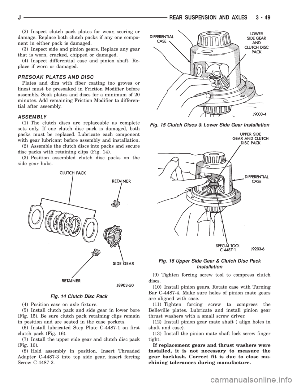
(2) Assemble the clutch discs into packs and secure
disc packs with retaining clips (Fig. 14).
(3) Position assembled clutch disc packs on the
side gear hubs.
(4) Position case on axle fixture.
(5) Install clutch pack and side gear in lower bore
(Fig. 15). Be sure clutch pack retaining clips remain
in position and are seated in the case pockets.
(6) Install lubricated Step Plate C-4487-1 on first
clutch pack (Fig. 16).
(7) Install the upper side gear and clutch disc pack
(Fig. 16).
(8) Hold assembly in position. Insert Threaded
Adapter C-4487-3 into top side gear, insert forcing
Screw C-4487-2.(9) Tighten forcing screw tool to compress clutch
discs.
(10) Install pinion gears. Rotate case with Turning
Bar C-4487-4. Make sure holes of pinion mate gears
are aligned with case.
(11) Tighten forcing screw to compress the
Belleville plates. Lubricate and install pinion gear
thrust washers with a small screw driver.
(12) Install pinion gear mate shaft ( align holes in
shaft and case).
(13) Install the pinion mate shaft lock screw finger
tight.
If replacement gears and thrust washers were
installed, it is not necessary to measure the
gear backlash. Correct fit is due to close ma-
chining tolerances during manufacture.
Fig. 14 Clutch Disc Pack
Fig. 15 Clutch Discs & Lower Side Gear Installation
Fig. 16 Upper Side Gear & Clutch Disc Pack
Installation
JREAR SUSPENSION AND AXLES 3 - 49