1995 JEEP XJ ECO mode
[x] Cancel search: ECO modePage 1715 of 2158
VALVE BODY ASSEMBLY AND ADJUSTMENT
CAUTION: Do not force valves or plugs into place
during reassembly. If the valve body bores, valves
and plugs are free of distortion or burrs, the valve
body components should all slide into place easily.
In addition, do not overtighten the transfer plate
and valve body screws during reassembly. Over-
tightening can distort the valve body resulting in
valve sticking, cross leakage and unsatisfactory op-
eration. Tighten valve body screws to recom-
mended torque only.
(1) Lubricate valve body bores, valves and plugs
with Mopar ATF Plus transmission fluid.
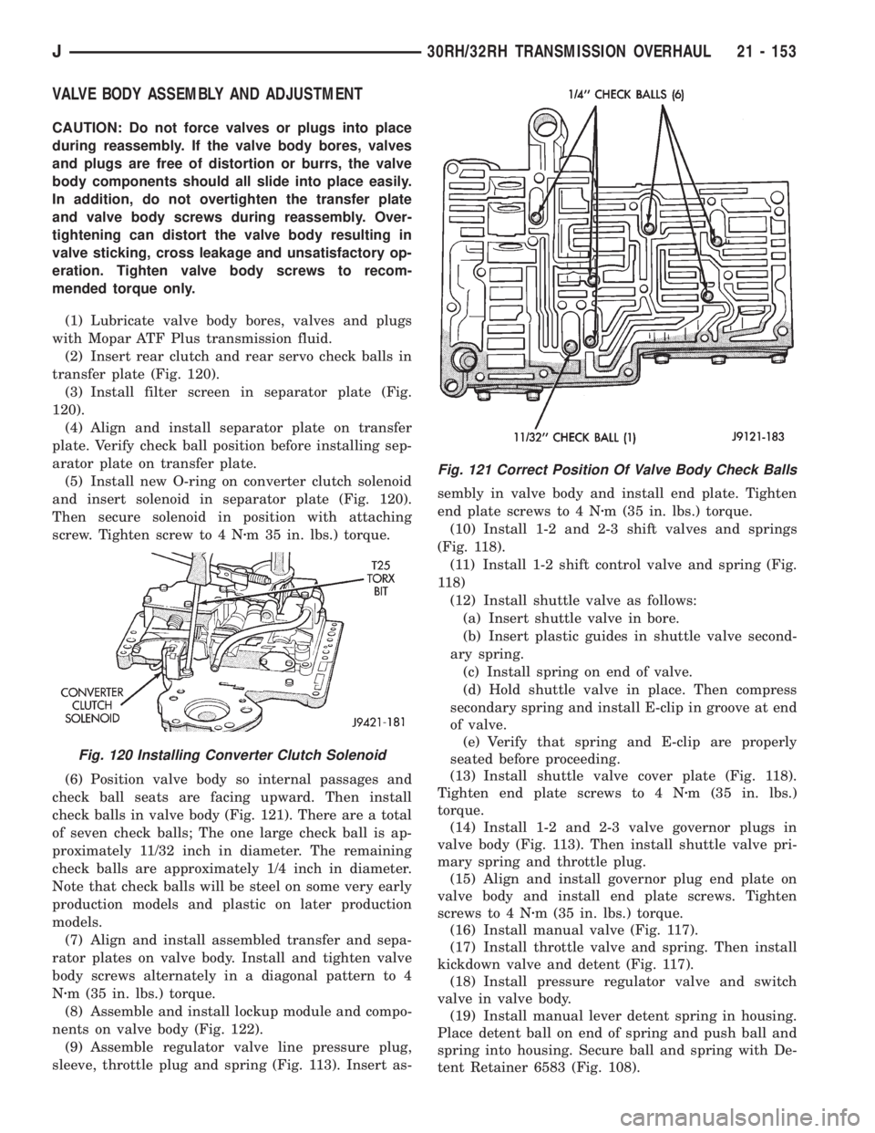
(2) Insert rear clutch and rear servo check balls in
transfer plate (Fig. 120).
(3) Install filter screen in separator plate (Fig.
120).
(4) Align and install separator plate on transfer
plate. Verify check ball position before installing sep-
arator plate on transfer plate.
(5) Install new O-ring on converter clutch solenoid
and insert solenoid in separator plate (Fig. 120).
Then secure solenoid in position with attaching
screw. Tighten screw to 4 Nzm 35 in. lbs.) torque.
(6) Position valve body so internal passages and
check ball seats are facing upward. Then install
check balls in valve body (Fig. 121). There are a total
of seven check balls; The one large check ball is ap-
proximately 11/32 inch in diameter. The remaining
check balls are approximately 1/4 inch in diameter.
Note that check balls will be steel on some very early
production models and plastic on later production
models.
(7) Align and install assembled transfer and sepa-
rator plates on valve body. Install and tighten valve
body screws alternately in a diagonal pattern to 4
Nzm (35 in. lbs.) torque.
(8) Assemble and install lockup module and compo-
nents on valve body (Fig. 122).
(9) Assemble regulator valve line pressure plug,
sleeve, throttle plug and spring (Fig. 113). Insert as-sembly in valve body and install end plate. Tighten
end plate screws to 4 Nzm (35 in. lbs.) torque.
(10) Install 1-2 and 2-3 shift valves and springs
(Fig. 118).
(11) Install 1-2 shift control valve and spring (Fig.
118)
(12) Install shuttle valve as follows:
(a) Insert shuttle valve in bore.
(b) Insert plastic guides in shuttle valve second-
ary spring.
(c) Install spring on end of valve.
(d) Hold shuttle valve in place. Then compress
secondary spring and install E-clip in groove at end
of valve.
(e) Verify that spring and E-clip are properly
seated before proceeding.
(13) Install shuttle valve cover plate (Fig. 118).
Tighten end plate screws to 4 Nzm (35 in. lbs.)
torque.
(14) Install 1-2 and 2-3 valve governor plugs in
valve body (Fig. 113). Then install shuttle valve pri-
mary spring and throttle plug.
(15) Align and install governor plug end plate on
valve body and install end plate screws. Tighten
screws to 4 Nzm (35 in. lbs.) torque.
(16) Install manual valve (Fig. 117).
(17) Install throttle valve and spring. Then install
kickdown valve and detent (Fig. 117).
(18) Install pressure regulator valve and switch
valve in valve body.
(19) Install manual lever detent spring in housing.
Place detent ball on end of spring and push ball and
spring into housing. Secure ball and spring with De-
tent Retainer 6583 (Fig. 108).
Fig. 120 Installing Converter Clutch Solenoid
Fig. 121 Correct Position Of Valve Body Check Balls
J30RH/32RH TRANSMISSION OVERHAUL 21 - 153
Page 1727 of 2158
AW-4 AUTOMATIC TRANSMISSION
CONTENTS
page page
AW-4 AUTOMATIC TRANSMISSION........ 165
AW-4 IN-VEHICLE SERVICE.............. 182
AW-4 TRANSMISSION DIAGNOSIS......... 176
AW-4 TRANSMISSION OVERHAUL......... 201AW-4 TRANSMISSION REMOVAL AND
INSTALLATION....................... 198
GENERAL INFORMATION................ 165
GENERAL INFORMATION
INDEX
page page
Components and Operation................. 166
Description............................. 165
First/Second/Third/Reverse Components....... 168
Fourth Gear Overdrive Components.......... 167
Geartrain Operation and Application Charts..... 169Hydraulic System........................ 169
Recommended Fluid and Capacity........... 166
Torque Converter........................ 167
Transmission Identification.................. 166
Transmission Ranges and Shift Lever Positions . . 166
DESCRIPTION
AW-4 Transmission Overhaul
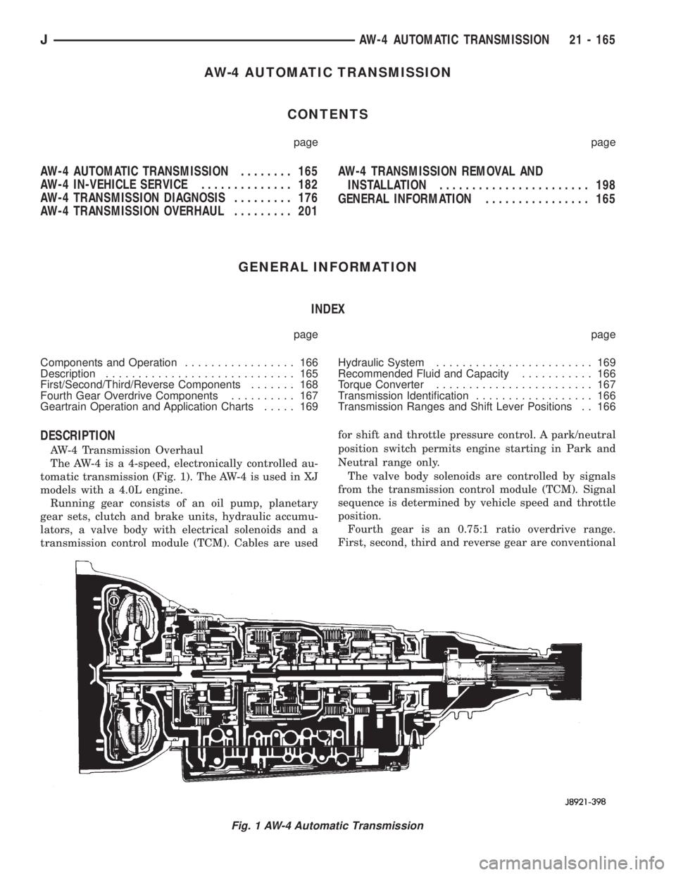
The AW-4 is a 4-speed, electronically controlled au-
tomatic transmission (Fig. 1). The AW-4 is used in XJ
models with a 4.0L engine.
Running gear consists of an oil pump, planetary
gear sets, clutch and brake units, hydraulic accumu-
lators, a valve body with electrical solenoids and a
transmission control module (TCM). Cables are usedfor shift and throttle pressure control. A park/neutral
position switch permits engine starting in Park and
Neutral range only.
The valve body solenoids are controlled by signals
from the transmission control module (TCM). Signal
sequence is determined by vehicle speed and throttle
position.
Fourth gear is an 0.75:1 ratio overdrive range.
First, second, third and reverse gear are conventional
Fig. 1 AW-4 Automatic Transmission
JAW-4 AUTOMATIC TRANSMISSION 21 - 165
Page 1728 of 2158
ranges. Third gear ratio is 1:1. A separate planetary
gear set provides overdrive operation in fourth gear.
TRANSMISSION RANGES AND SHIFT LEVER
POSITIONS
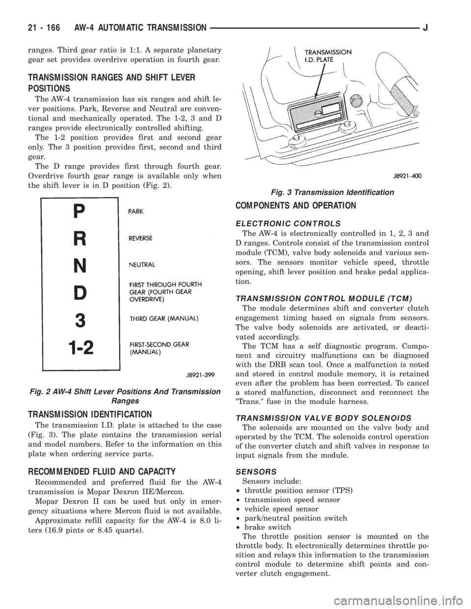
The AW-4 transmission has six ranges and shift le-
ver positions. Park, Reverse and Neutral are conven-
tional and mechanically operated. The 1-2, 3 and D
ranges provide electronically controlled shifting.
The 1-2 position provides first and second gear
only. The 3 position provides first, second and third
gear.
The D range provides first through fourth gear.
Overdrive fourth gear range is available only when
the shift lever is in D position (Fig. 2).
TRANSMISSION IDENTIFICATION
The transmission I.D. plate is attached to the case
(Fig. 3). The plate contains the transmission serial
and model numbers. Refer to the information on this
plate when ordering service parts.
RECOMMENDED FLUID AND CAPACITY
Recommended and preferred fluid for the AW-4
transmission is Mopar Dexron IIE/Mercon.
Mopar Dexron II can be used but only in emer-
gency situations where Mercon fluid is not available.
Approximate refill capacity for the AW-4 is 8.0 li-
ters (16.9 pints or 8.45 quarts).
COMPONENTS AND OPERATION
ELECTRONIC CONTROLS
The AW-4 is electronically controlled in 1, 2, 3 and
D ranges. Controls consist of the transmission control
module (TCM), valve body solenoids and various sen-
sors. The sensors monitor vehicle speed, throttle
opening, shift lever position and brake pedal applica-
tion.
TRANSMISSION CONTROL MODULE (TCM)
The module determines shift and converter clutch
engagement timing based on signals from sensors.
The valve body solenoids are activated, or deacti-
vated accordingly.
The TCM has a self diagnostic program. Compo-
nent and circuitry malfunctions can be diagnosed
with the DRB scan tool. Once a malfunction is noted
and stored in control module memory, it is retained
even after the problem has been corrected. To cancel
a stored malfunction, disconnect and reconnect the
9Trans.9fuse in the module harness.
TRANSMISSION VALVE BODY SOLENOIDS
The solenoids are mounted on the valve body and
operated by the TCM. The solenoids control operation
of the converter clutch and shift valves in response to
input signals from the module.
SENSORS
Sensors include:
²throttle position sensor (TPS)
²transmission speed sensor
²vehicle speed sensor
²park/neutral position switch
²brake switch
The throttle position sensor is mounted on the
throttle body. It electronically determines throttle po-
sition and relays this information to the transmission
control module to determine shift points and con-
verter clutch engagement.
Fig. 2 AW-4 Shift Lever Positions And Transmission
Ranges
Fig. 3 Transmission Identification
21 - 166 AW-4 AUTOMATIC TRANSMISSIONJ
Page 1745 of 2158
(6) Let engine run at normal curb idle speed, apply
service brakes. Then shift transmission through all
gear ranges and back to PARK (leave engine run-
ning).
(7) Remove dipstick and check fluid level. Add only
enough fluid to bring level to Full mark on dipstick.
Do not overfill.If too much fluid is added, excess
amount can be removed with suction gun and
plastic tubing. Tubing only has to be long
enough to extend into oil pan.
(8) When fluid level is correct, shut engine off, re-
lease park brake, remove funnel, and reseat dipstick
in fill tube.
TRANSMISSION CONTROL MODULE (TCM)
SERVICE
Use the DRB scan tool to diagnose transmission
control module function whenever a fault is sus-
pected. Replace the module only when the scan tool
indicates the module is actually faulty.
TRANSMISSION CONTROL MODULE
REPLACEMENT
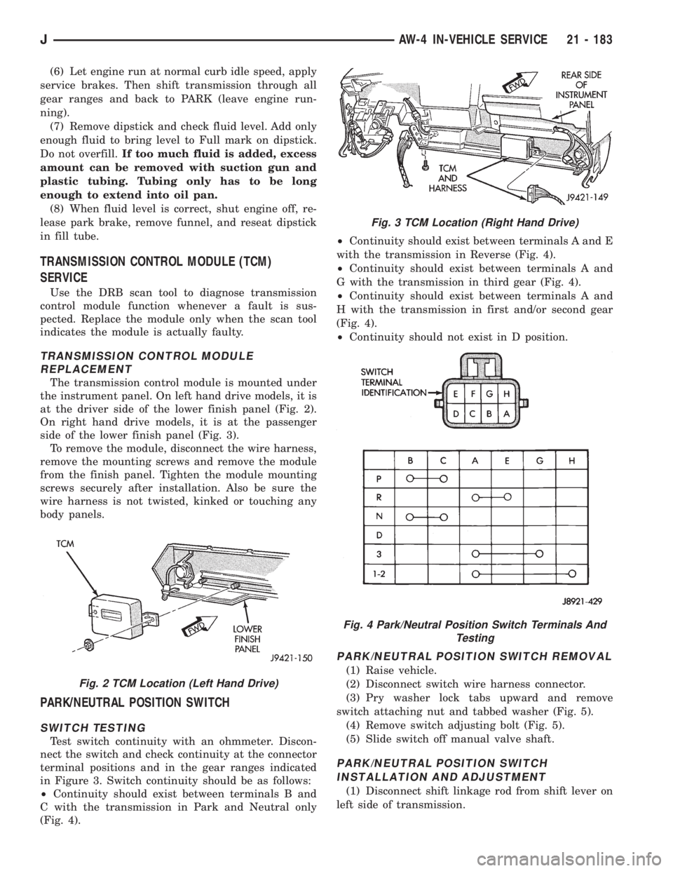
The transmission control module is mounted under
the instrument panel. On left hand drive models, it is
at the driver side of the lower finish panel (Fig. 2).
On right hand drive models, it is at the passenger
side of the lower finish panel (Fig. 3).
To remove the module, disconnect the wire harness,
remove the mounting screws and remove the module
from the finish panel. Tighten the module mounting
screws securely after installation. Also be sure the
wire harness is not twisted, kinked or touching any
body panels.
PARK/NEUTRAL POSITION SWITCH
SWITCH TESTING
Test switch continuity with an ohmmeter. Discon-
nect the switch and check continuity at the connector
terminal positions and in the gear ranges indicated
in Figure 3. Switch continuity should be as follows:
²Continuity should exist between terminals B and
C with the transmission in Park and Neutral only
(Fig. 4).²Continuity should exist between terminals A and E
with the transmission in Reverse (Fig. 4).
²Continuity should exist between terminals A and
G with the transmission in third gear (Fig. 4).
²Continuity should exist between terminals A and
H with the transmission in first and/or second gear
(Fig. 4).
²Continuity should not exist in D position.
PARK/NEUTRAL POSITION SWITCH REMOVAL
(1) Raise vehicle.
(2) Disconnect switch wire harness connector.
(3) Pry washer lock tabs upward and remove
switch attaching nut and tabbed washer (Fig. 5).
(4) Remove switch adjusting bolt (Fig. 5).
(5) Slide switch off manual valve shaft.
PARK/NEUTRAL POSITION SWITCH
INSTALLATION AND ADJUSTMENT
(1) Disconnect shift linkage rod from shift lever on
left side of transmission.
Fig. 2 TCM Location (Left Hand Drive)
Fig. 3 TCM Location (Right Hand Drive)
Fig. 4 Park/Neutral Position Switch Terminals And
Testing
JAW-4 IN-VEHICLE SERVICE 21 - 183
Page 1846 of 2158
OPERATING RANGES
NP231 operating ranges are: 2-wheel drive high;
4-wheel drive high and 4-wheel drive low.
2-wheel drive range is for use on all road surfaces.
The 4-wheel drive high and low ranges are undiffer-
entiated and should only be used on unpaved, low
traction surfaces only. The only exception being when
hard surface roads are snow and ice covered.
SHIFT MECHANISM
Operating ranges are selected with a floor mounted
shift lever. The shift lever is connected to the trans-
fer case range lever by an adjustable linkage rod. A
straight line shift pattern is used. Range positions
are marked on the shifter bezel cover plate, or on the
shift knob.
TRANSFER CASE IDENTIFICATION
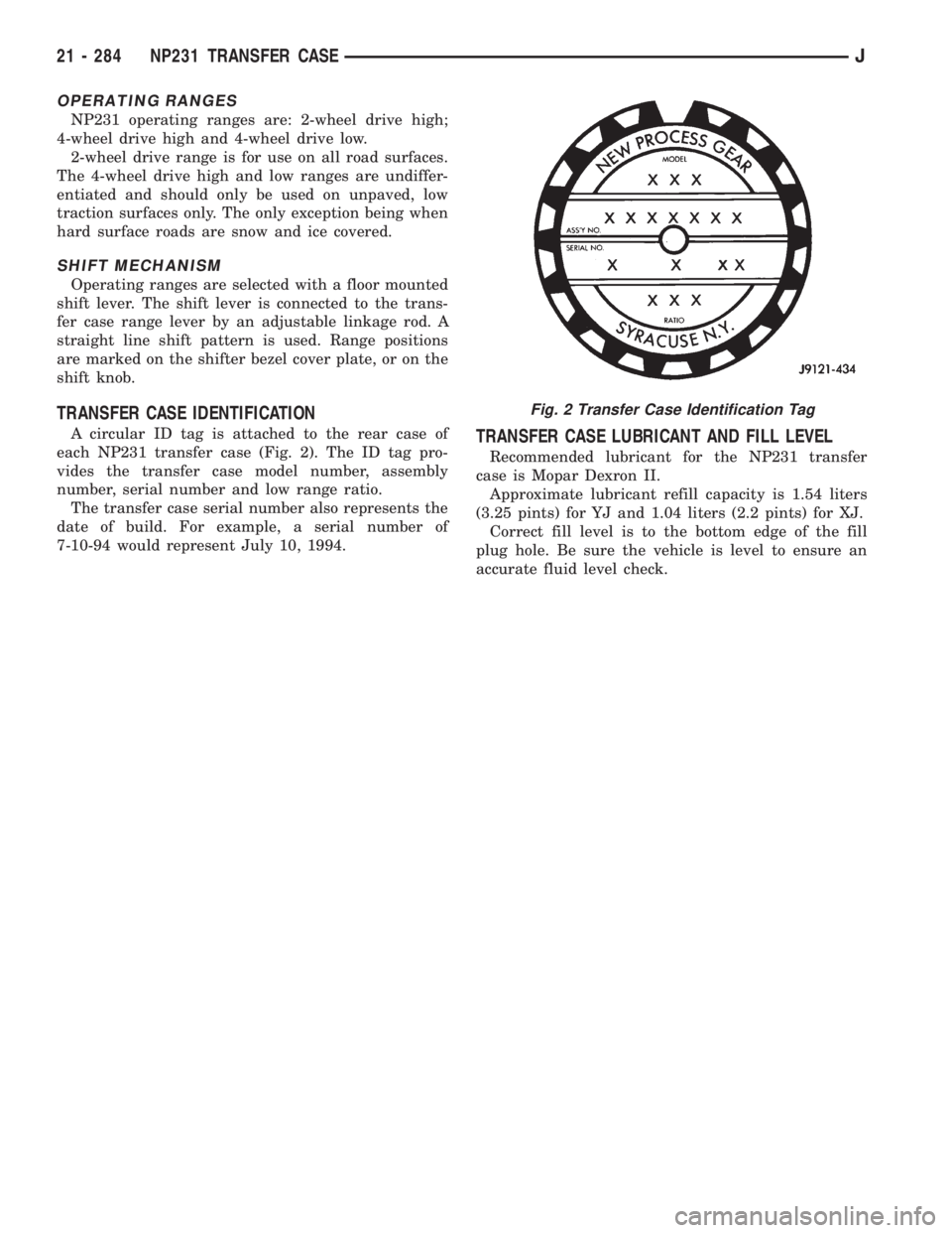
A circular ID tag is attached to the rear case of
each NP231 transfer case (Fig. 2). The ID tag pro-
vides the transfer case model number, assembly
number, serial number and low range ratio.
The transfer case serial number also represents the
date of build. For example, a serial number of
7-10-94 would represent July 10, 1994.TRANSFER CASE LUBRICANT AND FILL LEVEL
Recommended lubricant for the NP231 transfer
case is Mopar Dexron II.
Approximate lubricant refill capacity is 1.54 liters
(3.25 pints) for YJ and 1.04 liters (2.2 pints) for XJ.
Correct fill level is to the bottom edge of the fill
plug hole. Be sure the vehicle is level to ensure an
accurate fluid level check.
Fig. 2 Transfer Case Identification Tag
21 - 284 NP231 TRANSFER CASEJ
Page 1856 of 2158
OVERHAUL CLEANING AND INSPECTION
Clean the transfer case components thoroughly
with solvent. Remove all traces of sealer from the
case and retainer seal surfaces.
Clean the oil pickup screen with solvent. Shake ex-
cess solvent from screen and allow it air dry. Use
compressed air to remove solvent residue from all oil
feed passages and channels in the case halves.
Inspect the splines and bearing surfaces on the
both shafts. Replace either shaft as necessary if wear,
or damage is evident.
Check condition of the shift forks, fork pads and
shift rail. Minor scratches/nicks on the rail can be
smoothed with 320/400 grit emery cloth. Replace the
mode fork pads if worn. Replace the range fork if the
pads are worn, missing, or damaged.
On synchro equipped models, inspect the synchro
sleeve, hub, struts, springs, and the stop ring. Re-
place worn, or damaged parts as necessary.
Do not attempt to salvage and reuse snap rings
that were bent, or distorted. It is recommended that
all snap rings be replaced during overhaul.Replace the front yoke nut as it should not be re-
used. Also replace the rubber seal if worn, cut, or
torn.
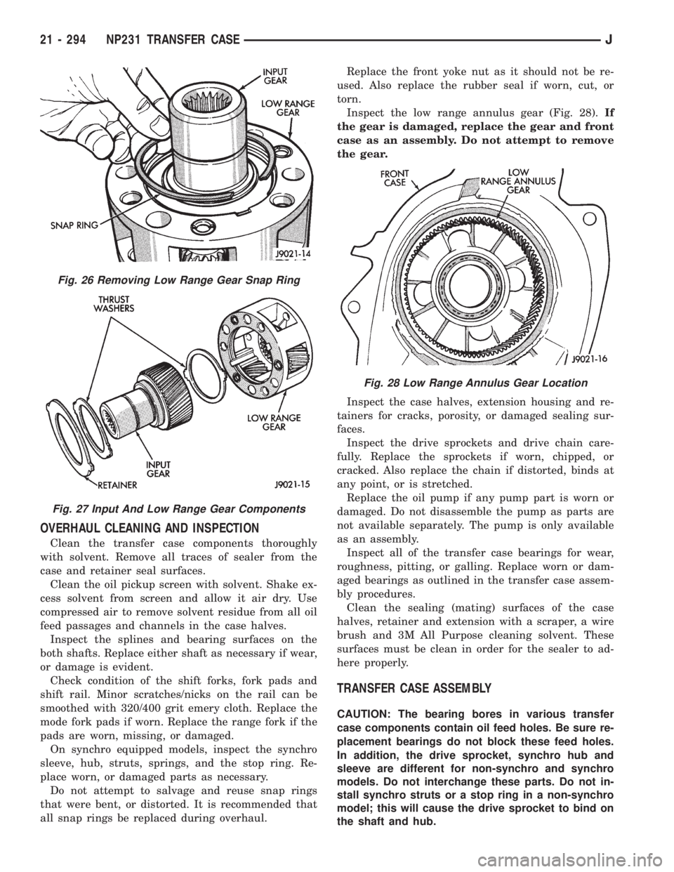
Inspect the low range annulus gear (Fig. 28).If
the gear is damaged, replace the gear and front
case as an assembly. Do not attempt to remove
the gear.
Inspect the case halves, extension housing and re-
tainers for cracks, porosity, or damaged sealing sur-
faces.
Inspect the drive sprockets and drive chain care-
fully. Replace the sprockets if worn, chipped, or
cracked. Also replace the chain if distorted, binds at
any point, or is stretched.
Replace the oil pump if any pump part is worn or
damaged. Do not disassemble the pump as parts are
not available separately. The pump is only available
as an assembly.
Inspect all of the transfer case bearings for wear,
roughness, pitting, or galling. Replace worn or dam-
aged bearings as outlined in the transfer case assem-
bly procedures.
Clean the sealing (mating) surfaces of the case
halves, retainer and extension with a scraper, a wire
brush and 3M All Purpose cleaning solvent. These
surfaces must be clean in order for the sealer to ad-
here properly.
TRANSFER CASE ASSEMBLY
CAUTION: The bearing bores in various transfer
case components contain oil feed holes. Be sure re-
placement bearings do not block these feed holes.
In addition, the drive sprocket, synchro hub and
sleeve are different for non-synchro and synchro
models. Do not interchange these parts. Do not in-
stall synchro struts or a stop ring in a non-synchro
model; this will cause the drive sprocket to bind on
the shaft and hub.
Fig. 26 Removing Low Range Gear Snap Ring
Fig. 27 Input And Low Range Gear Components
Fig. 28 Low Range Annulus Gear Location
21 - 294 NP231 TRANSFER CASEJ
Page 1869 of 2158
NP242 TRANSFER CASE
INDEX
page page
General Information....................... 307
Operating Ranges........................ 307
Overhaul Cleaning and Inspection............ 318
Recommended Lubricant/Capacity/Fill Level..... 307
Shift Lever Installation (XJ)................. 309
Shift Lever Removal (XJ)................... 309
Shift Linkage Adjustment................... 309
Shift Mechanism......................... 307Speedometer Service..................... 309
Transfer Case Assembly................... 319
Transfer Case Changes.................... 307
Transfer Case Disassembly and Overhaul...... 310
Transfer Case Identification................. 307
Transfer Case Installation.................. 309
Transfer Case Removal.................... 309
GENERAL INFORMATION
The NP242 is a full and part-time transfer case
(Fig. 1). It provides full time 2-wheel, or 4-wheel
drive operation. The NP242 is used in XJ models.
A differential in the transfer case is used to control
torque transfer to the front and rear axles. A low
range gear provides increased low speed torque capa-
bility for off road operation. The low range provides a
2.72:1 reduction ratio.
OPERATING RANGES
NP242 operating ranges are 2WD (2-wheel drive),
4x4 part-time, 4x4 full time, and 4 Lo.
The 2WD and 4x4 full time ranges can be used at
any time and on any road surface.
The 4x4 part-time and 4 Lo ranges are for off road use
only. The only time these ranges can be used on hard sur-
face roads, is when the surface is covered with snow and
ice.
SHIFT MECHANISM
Transfer case operating ranges are selected with a floor
mounted shift lever. The shift lever is connected to the trans-fer case range lever by an adjustable linkage rod. Range po-
sitions are marked on the shift knob or shifter bezel plate.
TRANSFER CASE IDENTIFICATION
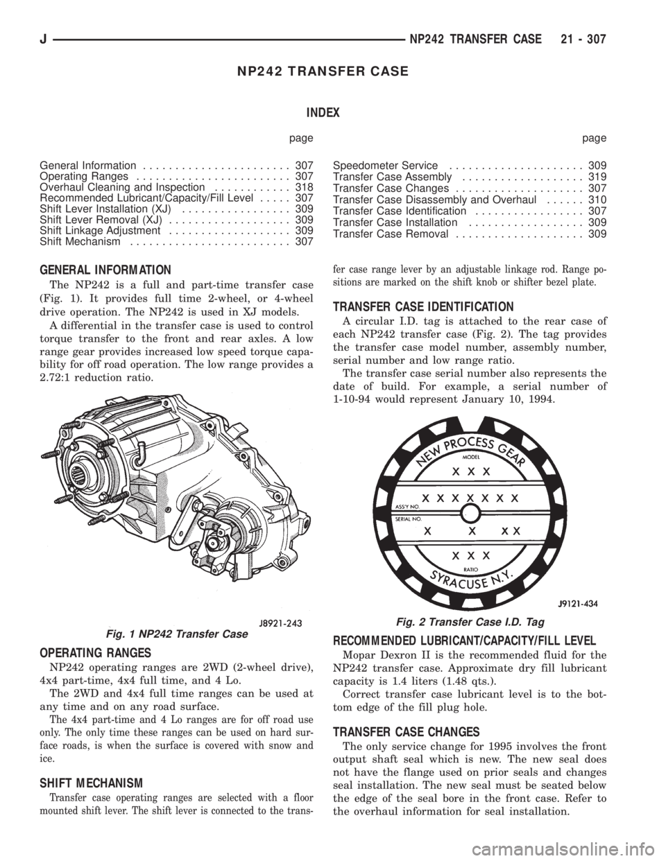
A circular I.D. tag is attached to the rear case of
each NP242 transfer case (Fig. 2). The tag provides
the transfer case model number, assembly number,
serial number and low range ratio.
The transfer case serial number also represents the
date of build. For example, a serial number of
1-10-94 would represent January 10, 1994.
RECOMMENDED LUBRICANT/CAPACITY/FILL LEVEL
Mopar Dexron II is the recommended fluid for the
NP242 transfer case. Approximate dry fill lubricant
capacity is 1.4 liters (1.48 qts.).
Correct transfer case lubricant level is to the bot-
tom edge of the fill plug hole.
TRANSFER CASE CHANGES
The only service change for 1995 involves the front
output shaft seal which is new. The new seal does
not have the flange used on prior seals and changes
seal installation. The new seal must be seated below
the edge of the seal bore in the front case. Refer to
the overhaul information for seal installation.
Fig. 1 NP242 Transfer Case
Fig. 2 Transfer Case I.D. Tag
JNP242 TRANSFER CASE 21 - 307
Page 1908 of 2158
TIRE CHAINS
Tire snow chains may be used on certain models.
Refer to Owner's Manual for more information.
CLEANING OF TIRES
Steam cleaning may be used for cleaning.
DO NOT use gasoline or wire brush for cleaning.
DO NOT use mineral oil or an oil-based solvent.
PRESSURE GAUGES
High-quality, dial-type, air-pressure gauges are rec-
ommended. After checking with the gauge, replace
valve cap and finger tight.
TIRE INFLATION PRESSURES
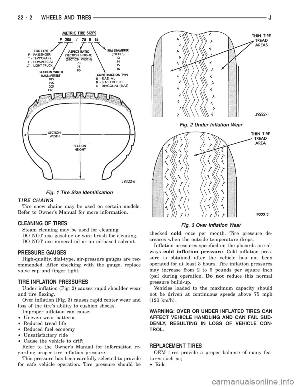
Under inflation (Fig. 2) causes rapid shoulder wear
and tire flexing.
Over inflation (Fig. 3) causes rapid center wear and
loss of the tire's ability to cushion shocks.
Improper inflation can cause;
²Uneven wear patterns
²Reduced tread life
²Reduced fuel economy
²Unsatisfactory ride
²Cause the vehicle to drift
Refer to the Owner's Manual for information re-
garding proper tire inflation pressure.
This pressure has been carefully selected to provide
for safe vehicle operation. Tire pressure should becheckedcoldonce per month. Tire pressure de-
creases when the outside temperature drops.
Inflation pressures specified on the placards are al-
wayscold inflation pressure. Cold inflation pres-
sure is obtained after the vehicle has not been
operated for at least 3 hours. Tire inflation pressures
may increase from 2 to 6 pounds per square inch
(psi) during operation.Do notreduce this normal
pressure build-up.
Vehicles loaded to the maximum capacity should
not be driven at continuous speeds above 75 mph
(120 km/h).
WARNING: OVER OR UNDER INFLATED TIRES CAN
AFFECT VEHICLE HANDLING AND CAN FAIL SUD-
DENLY, RESULTING IN LOSS OF VEHICLE CON-
TROL.
REPLACEMENT TIRES
OEM tires provide a proper balance of many fea-
tures such as;
²Ride
Fig. 1 Tire Size Identification
Fig. 2 Under Inflation Wear
Fig. 3 Over Inflation Wear
22 - 2 WHEELS AND TIRESJ