1995 JEEP XJ ECO mode
[x] Cancel search: ECO modePage 1456 of 2158
EXAMPLES:
²If the lamp (Figs. 45 or 46) flashes 1 time, pauses
and flashes 2 more times, a flashing Diagnostic Trou-
ble Code (DTC) number 12 is indicated. If this code is
observed, it is indicating that the battery has been
disconnected within the last 50 key-on cycles. It
could also indicate that battery voltage has been dis-
connected to the PCM. In either case, other DTC's
may have been erased.
²If the lamp flashes 4 times, pauses and flashes 1
more time, a flashing Diagnostic Trouble Code (DTC)
number 41 is indicated.
²If the lamp flashes 4 times, pauses and flashes 6
more times, a flashing Diagnostic Trouble Code
(DTC) number 46 is indicated.
After any stored DTC information has been ob-
served, the display will end with a flashing DTC
number 55. This will indicate the end of all stored in-
formation.
Refer to the Diagnostic Trouble Code (DTC) charts
for DTC identification.If the problem is repaired or ceases to exist, the
Powertrain Control Module (PCM) cancels the DTC
after 51 engine starts.
Diagnostic Trouble Codes indicate the results of a
failure, but never identify the failed component di-
rectly.
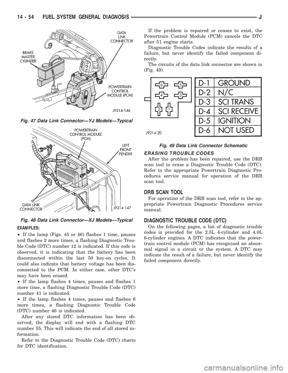
The circuits of the data link connector are shown in
(Fig. 49).
ERASING TROUBLE CODES
After the problem has been repaired, use the DRB
scan tool to erase a Diagnostic Trouble Code (DTC).
Refer to the appropriate Powertrain Diagnostic Pro-
cedures service manual for operation of the DRB
scan tool.
DRB SCAN TOOL
For operation of the DRB scan tool, refer to the ap-
propriate Powertrain Diagnostic Procedures service
manual.
DIAGNOSTIC TROUBLE CODE (DTC)
On the following pages, a list of diagnostic trouble
codes is provided for the 2.5L 4-cylinder and 4.0L
6-cylinder engines. A DTC indicates that the power-
train control module (PCM) has recognized an abnor-
mal signal in a circuit or the system. A DTC may
indicate the result of a failure, but never identify the
failed component directly.
Fig. 47 Data Link ConnectorÐYJ ModelsÐTypical
Fig. 48 Data Link ConnectorÐXJ ModelsÐTypical
Fig. 49 Data Link Connector Schematic
14 - 54 FUEL SYSTEM GENERAL DIAGNOSISJ
Page 1465 of 2158
INTAKE MANIFOLD
Refer to Group 11, Exhaust System and Intake
Manifold for removal/installation procedures.
MANIFOLD ABSOLUTE PRESSURE (MAP) SENSOR
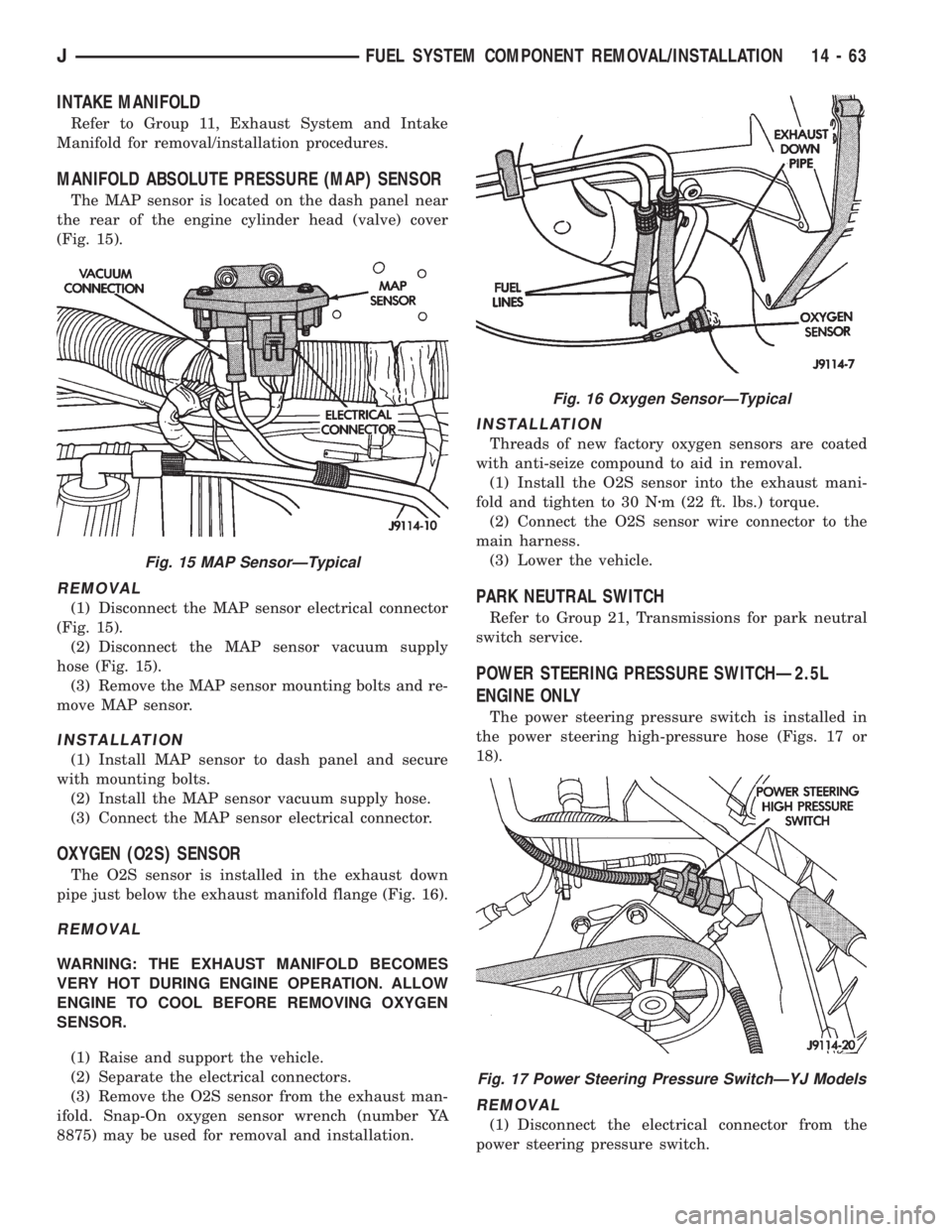
The MAP sensor is located on the dash panel near
the rear of the engine cylinder head (valve) cover
(Fig. 15).
REMOVAL
(1) Disconnect the MAP sensor electrical connector
(Fig. 15).
(2) Disconnect the MAP sensor vacuum supply
hose (Fig. 15).
(3) Remove the MAP sensor mounting bolts and re-
move MAP sensor.
INSTALLATION
(1) Install MAP sensor to dash panel and secure
with mounting bolts.
(2) Install the MAP sensor vacuum supply hose.
(3) Connect the MAP sensor electrical connector.
OXYGEN (O2S) SENSOR
The O2S sensor is installed in the exhaust down
pipe just below the exhaust manifold flange (Fig. 16).
REMOVAL
WARNING: THE EXHAUST MANIFOLD BECOMES
VERY HOT DURING ENGINE OPERATION. ALLOW
ENGINE TO COOL BEFORE REMOVING OXYGEN
SENSOR.
(1) Raise and support the vehicle.
(2) Separate the electrical connectors.
(3) Remove the O2S sensor from the exhaust man-
ifold. Snap-On oxygen sensor wrench (number YA
8875) may be used for removal and installation.
INSTALLATION
Threads of new factory oxygen sensors are coated
with anti-seize compound to aid in removal.
(1) Install the O2S sensor into the exhaust mani-
fold and tighten to 30 Nzm (22 ft. lbs.) torque.
(2) Connect the O2S sensor wire connector to the
main harness.
(3) Lower the vehicle.
PARK NEUTRAL SWITCH
Refer to Group 21, Transmissions for park neutral
switch service.
POWER STEERING PRESSURE SWITCHÐ2.5L
ENGINE ONLY
The power steering pressure switch is installed in
the power steering high-pressure hose (Figs. 17 or
18).
REMOVAL
(1) Disconnect the electrical connector from the
power steering pressure switch.
Fig. 15 MAP SensorÐTypical
Fig. 16 Oxygen SensorÐTypical
Fig. 17 Power Steering Pressure SwitchÐYJ Models
JFUEL SYSTEM COMPONENT REMOVAL/INSTALLATION 14 - 63
Page 1563 of 2158
TRANSMISSION AND TRANSFER CASE
CONTENTS
page page
30RH/32RH AUTOMATIC TRANSMISSION.... 67
AW 4 AUTOMATIC TRANSMISSION........ 165
AX 15 MANUAL TRANSMISSION........... 33
AX 4/5 MANUAL TRANSMISSION............ 1NP231 TRANSFER CASE................. 283
NP242 TRANSFER CASE................. 306
TRANSMISSION/TRANSFER CASE
SPECIFICATIONS..................... 333
AX 4/5 MANUAL TRANSMISSION
INDEX
page page
Cleaning and Inspection.................... 13
Gear Ratios.............................. 2
General Information........................ 1
Recommended Lubricant.................... 2
Service Diagnosis.......................... 2
Shift Pattern.............................. 2Transmission Assembly and Adjustment......... 16
Transmission Disassembly and Overhaul......... 5
Transmission Identification................... 2
Transmission Installation..................... 5
Transmission Removal...................... 3
GENERAL INFORMATION
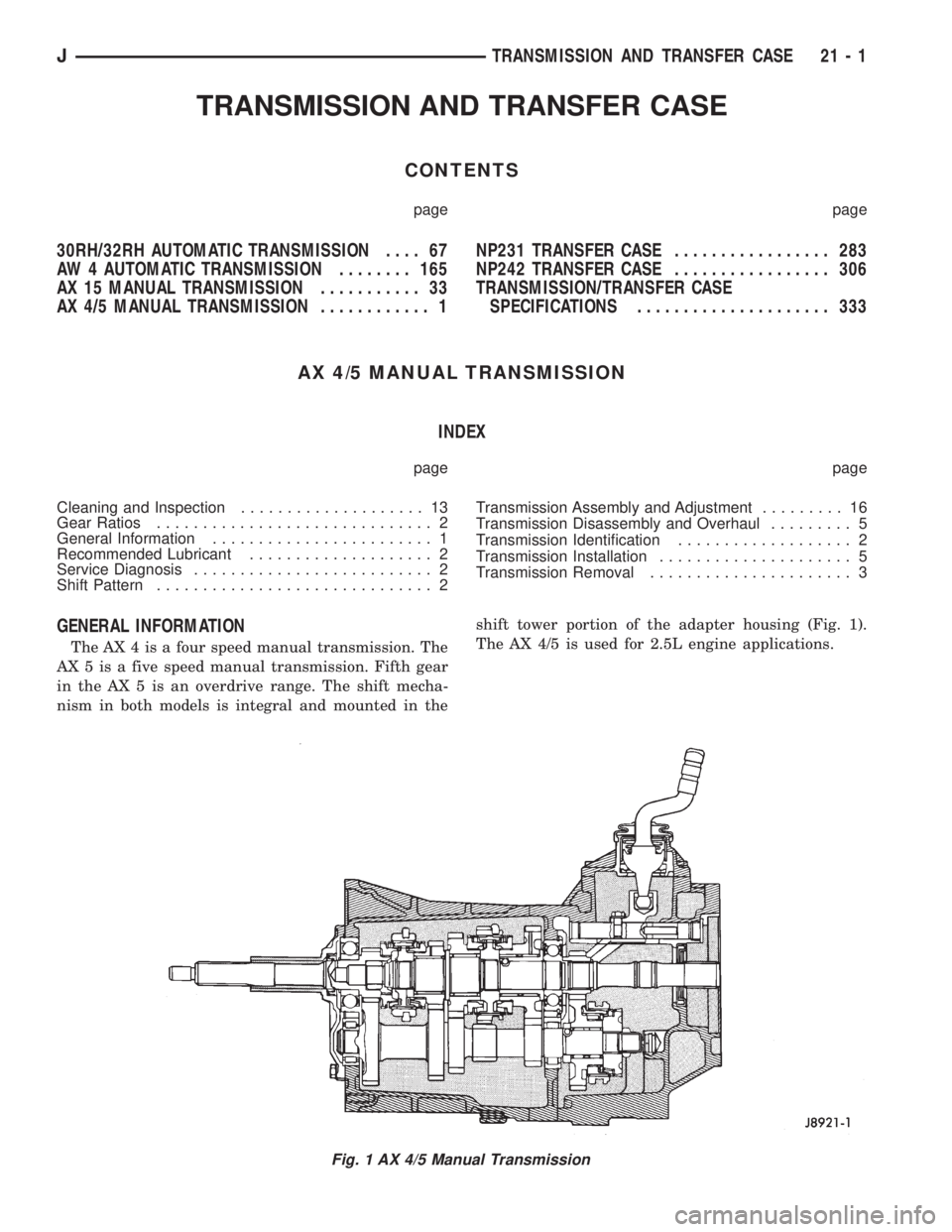
The AX 4 is a four speed manual transmission. The
AX 5 is a five speed manual transmission. Fifth gear
in the AX 5 is an overdrive range. The shift mecha-
nism in both models is integral and mounted in theshift tower portion of the adapter housing (Fig. 1).
The AX 4/5 is used for 2.5L engine applications.
Fig. 1 AX 4/5 Manual Transmission
JTRANSMISSION AND TRANSFER CASE 21 - 1
Page 1596 of 2158
The first number is year of manufacture. The sec-
ond and third numbers indicate month of manufac-
ture. The next series of numbers is the transmission
serial number.
TRANSMISSION SHIFT PATTERN
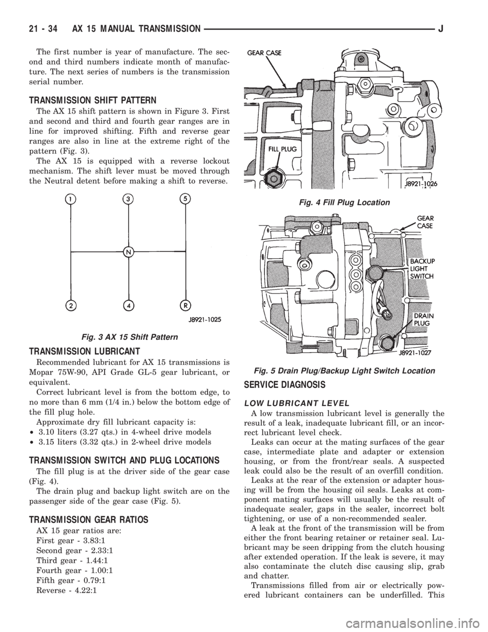
The AX 15 shift pattern is shown in Figure 3. First
and second and third and fourth gear ranges are in
line for improved shifting. Fifth and reverse gear
ranges are also in line at the extreme right of the
pattern (Fig. 3).
The AX 15 is equipped with a reverse lockout
mechanism. The shift lever must be moved through
the Neutral detent before making a shift to reverse.
TRANSMISSION LUBRICANT
Recommended lubricant for AX 15 transmissions is
Mopar 75W-90, API Grade GL-5 gear lubricant, or
equivalent.
Correct lubricant level is from the bottom edge, to
no more than 6 mm (1/4 in.) below the bottom edge of
the fill plug hole.
Approximate dry fill lubricant capacity is:
²3.10 liters (3.27 qts.) in 4-wheel drive models
²3.15 liters (3.32 qts.) in 2-wheel drive models
TRANSMISSION SWITCH AND PLUG LOCATIONS
The fill plug is at the driver side of the gear case
(Fig. 4).
The drain plug and backup light switch are on the
passenger side of the gear case (Fig. 5).
TRANSMISSION GEAR RATIOS
AX 15 gear ratios are:
First gear - 3.83:1
Second gear - 2.33:1
Third gear - 1.44:1
Fourth gear - 1.00:1
Fifth gear - 0.79:1
Reverse - 4.22:1
SERVICE DIAGNOSIS
LOW LUBRICANT LEVEL
A low transmission lubricant level is generally the
result of a leak, inadequate lubricant fill, or an incor-
rect lubricant level check.
Leaks can occur at the mating surfaces of the gear
case, intermediate plate and adapter or extension
housing, or from the front/rear seals. A suspected
leak could also be the result of an overfill condition.
Leaks at the rear of the extension or adapter hous-
ing will be from the housing oil seals. Leaks at com-
ponent mating surfaces will usually be the result of
inadequate sealer, gaps in the sealer, incorrect bolt
tightening, or use of a non-recommended sealer.
A leak at the front of the transmission will be from
either the front bearing retainer or retainer seal. Lu-
bricant may be seen dripping from the clutch housing
after extended operation. If the leak is severe, it may
also contaminate the clutch disc causing slip, grab
and chatter.
Transmissions filled from air or electrically pow-
ered lubricant containers can be underfilled. This
Fig. 3 AX 15 Shift Pattern
Fig. 4 Fill Plug Location
Fig. 5 Drain Plug/Backup Light Switch Location
21 - 34 AX 15 MANUAL TRANSMISSIONJ
Page 1629 of 2158
30RH/32RH AUTOMATIC TRANSMISSION
GENERAL INFORMATION
INDEX
page page
Recommended Fluid....................... 67
Torque Converter......................... 67
Transmission Application.................... 67
Transmission Changes and Parts Interchangeability.. 67
Transmission Controls and Components........ 67
Transmission Identification.................. 67
TRANSMISSION APPLICATION
Chrysler 30RH and 32RH automatic transmissions
are used in XJ/YJ models. Both are 3-speed auto-
matic transmissions with a gear-type oil pump, two
clutches and bands and a planetary gear system (Fig.
1).
The 30RH is used in XJ/YJ models with a 2.5L en-
gine. The 32RH is used in YJ models with a 4.0L en-
gine.
TORQUE CONVERTER
A three element, torque converter is used for all
applications. The converter consists of an impeller,
stator, and turbine.
The converter used with 30RH/32RH transmissions
has a converter clutch. The clutch is engaged by an
electrical solenoid and mechanical module on the
valve body. The solenoid is operated by the power-
train control module.
The torque converter is a welded assembly and is
not a repairable component. The converter is serviced
as an assembly.
RECOMMENDED FLUID
The recommended and preferred fluid for 30RH/
32RH transmissions is Mopar ATF Plus, Type 7176.
Dexron II is not really recommended and should
only be used when ATF Plus is not available.
TRANSMISSION IDENTIFICATION
The transmission identification numbers are
stamped on the left side of the case just above the oil
pan gasket surface (Fig. 2). The first set of numbers
is the transmission part number. The next set of code
numbers set is the date of build. The final set of code
numbers represents the transmission serial number.
TRANSMISSION CHANGES AND PARTS
INTERCHANGEABILITY
1995 transmissions are similar to previous models
but only in appearance. Current transmissions are
dimensionally different. Do not interchange new/oldparts. Different dimensions, fluid passages, input/
output shafts, cases, bands, valve bodies and gover-
nor assemblies are just a few of the changed items.
CAUTION: Special bolts are used to attach the
driveplate to the crankshaft on models with a 2.5L
engine and 30RH transmission,. These bolts have a
smaller hex head for torque converter clearance.
DO NOT interchange these bolts with similar size
bolts for any reason.
Different governor weight assemblies are used in
30RH/32RH transmissions. The 30RH weight assem-
bly is much the same as in previous years. However,
the 32RH has a three stage governor weight assem-
bly consisting of the outer weight, a smaller weight
spring, and a new intermediate weight. Refer to the
overhaul and in-vehicle service sections for more de-
tailed information.
Plastic check balls are now used in many 30RH/
32RH valve bodies. The new check balls entered pro-
duction as a running change. Plastic and steel check
balls are not interchangeable.
A converter drainback check valve has been added
to the fluid cooler system. The one-way valve is lo-
cated in the transmission outlet (pressure) line. The
valve prevents fluid drainback when the vehicle is
parked for lengthy periods.
TRANSMISSION CONTROLS AND COMPONENTS
The transmission hydraulic control system per-
forms five basic functions, which are:
²pressure supply
²pressure regulation
²flow control
²clutch/band apply and release
²lubrication
Pressure Supply And Regulation
The oil pump generates the fluid working pressure
needed for operation and lubrication. The pump is
J30RH/32RH AUTOMATIC TRANSMISSION 21 - 67
Page 1670 of 2158
bind if misalignment occurs. Remove and repo-
sition governor body if necessary.
(9) Verify that shaft bore in governor body and out-
put shaft are aligned.
(10) Verify that governor valve will be indexed
with spotface in output shaft. Reposition valve, shaft
and body if necessary.
(11) Install an E-clip on one end of governor valve
shaft. Be sure rounded side of E-clip is facing out
(away from weight).
(12) Insert governor valve shaft through governor
weight. Be sure shaft slides freely in bore.
(13) Install governor valve on shaft and in gover-
nor body bore.
(14) Install remaining E-clip on governor valve
shaft. Be sure rounded side of E-clip is facing out
(away from valve).
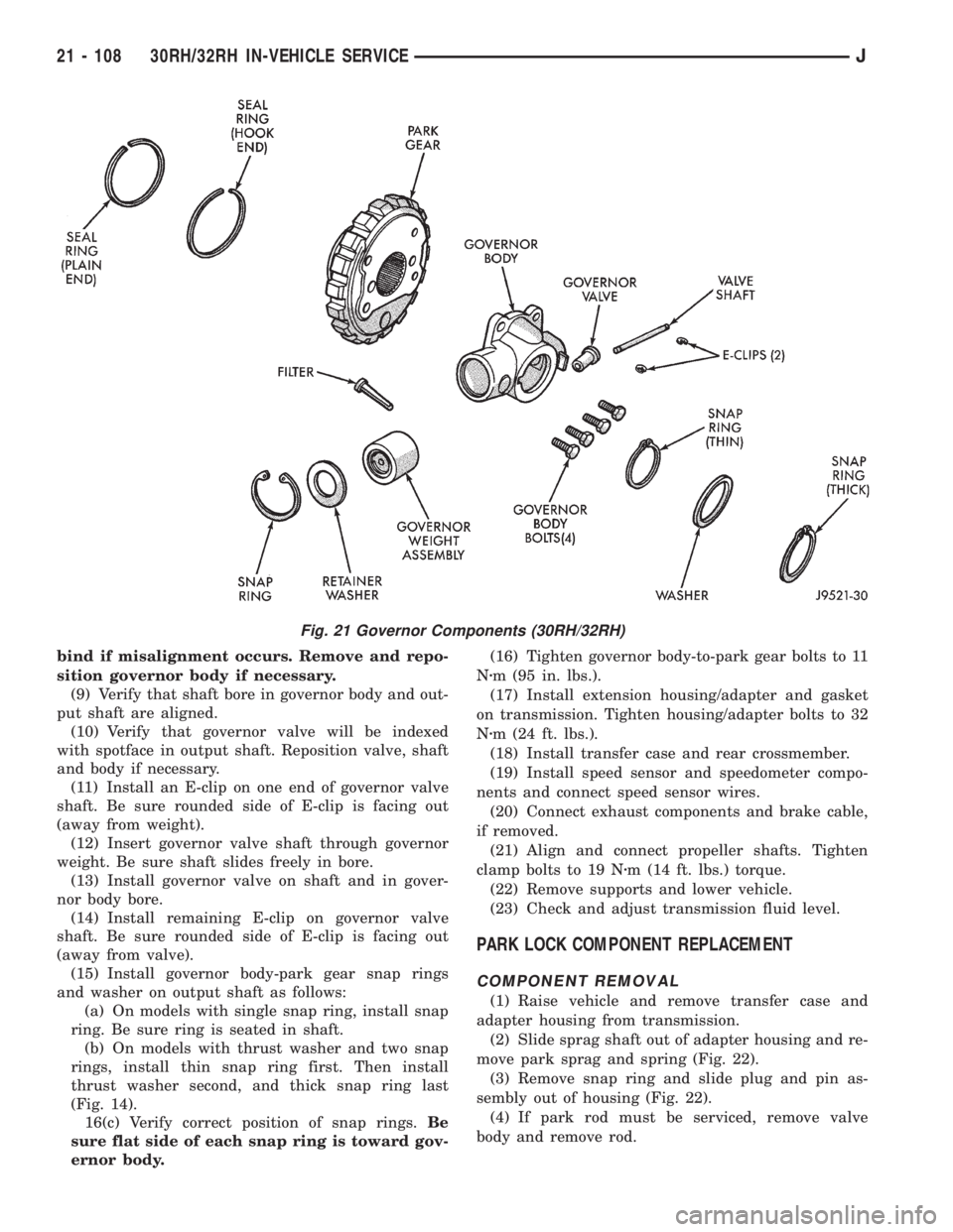
(15) Install governor body-park gear snap rings
and washer on output shaft as follows:
(a) On models with single snap ring, install snap
ring. Be sure ring is seated in shaft.
(b) On models with thrust washer and two snap
rings, install thin snap ring first. Then install
thrust washer second, and thick snap ring last
(Fig. 14).
16(c) Verify correct position of snap rings.Be
sure flat side of each snap ring is toward gov-
ernor body.(16) Tighten governor body-to-park gear bolts to 11
Nzm (95 in. lbs.).
(17) Install extension housing/adapter and gasket
on transmission. Tighten housing/adapter bolts to 32
Nzm (24 ft. lbs.).
(18) Install transfer case and rear crossmember.
(19) Install speed sensor and speedometer compo-
nents and connect speed sensor wires.
(20) Connect exhaust components and brake cable,
if removed.
(21) Align and connect propeller shafts. Tighten
clamp bolts to 19 Nzm (14 ft. lbs.) torque.
(22) Remove supports and lower vehicle.
(23) Check and adjust transmission fluid level.
PARK LOCK COMPONENT REPLACEMENT
COMPONENT REMOVAL
(1) Raise vehicle and remove transfer case and
adapter housing from transmission.
(2) Slide sprag shaft out of adapter housing and re-
move park sprag and spring (Fig. 22).
(3) Remove snap ring and slide plug and pin as-
sembly out of housing (Fig. 22).
(4) If park rod must be serviced, remove valve
body and remove rod.
Fig. 21 Governor Components (30RH/32RH)
21 - 108 30RH/32RH IN-VEHICLE SERVICEJ
Page 1689 of 2158
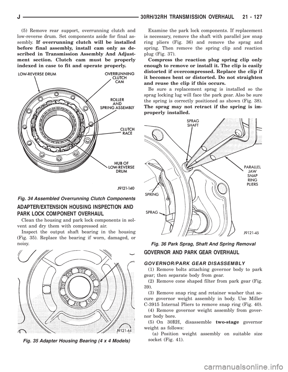
(5) Remove rear support, overrunning clutch and
low-reverse drum. Set components aside for final as-
sembly.If overrunning clutch will be installed
before final assembly, install cam only as de-
scribed in Transmission Assembly And Adjust-
ment section. Clutch cam must be properly
indexed in case to fit and operate properly.
ADAPTER/EXTENSION HOUSING INSPECTION AND
PARK LOCK COMPONENT OVERHAUL
Clean the housing and park lock components in sol-
vent and dry them with compressed air.
Inspect the output shaft bearing in the housing
(Fig. 35). Replace the bearing if worn, damaged, or
noisy.Examine the park lock components. If replacement
is necessary, remove the shaft with parallel jaw snap
ring pliers (Fig. 36) and remove the sprag and
spring. Then remove the spring clip and reaction
plug (Fig. 37).
Compress the reaction plug spring clip only
enough to remove or install it. The clip is easily
distorted if overcompressed. Replace the clip if
it becomes bent or distorted. Do not straighten
and reuse the clip if this occurs.
Be sure a replacement sprag is installed so the
sprag locking lug will face the park gear. Also be sure
the spring is correctly positioned as shown (Fig. 38).
The sprag may not retract if the spring is im-
properly installed.
GOVERNOR AND PARK GEAR OVERHAUL
GOVERNOR/PARK GEAR DISASSEMBLY
(1) Remove bolts attaching governor body to park
gear; then separate body from gear.
(2) Remove cone shaped filter from park gear (Fig.
39).
(3) Remove snap ring and retainer washer that se-
cure governor weight assembly in body. Use Miller
C-3915 Internal Pliers to remove snap ring (Fig. 40).
(4) Remove governor weight assembly from gover-
nor body bore.
(5) On 30RH, disassembletwo-stagegovernor
weight as follows:
(a) Position weight assembly on suitable size
socket (Fig. 41).
Fig. 34 Assembled Overrunning Clutch Components
Fig. 35 Adapter Housing Bearing (4 x 4 Models)
Fig. 36 Park Sprag, Shaft And Spring Removal
J30RH/32RH TRANSMISSION OVERHAUL 21 - 127
Page 1711 of 2158
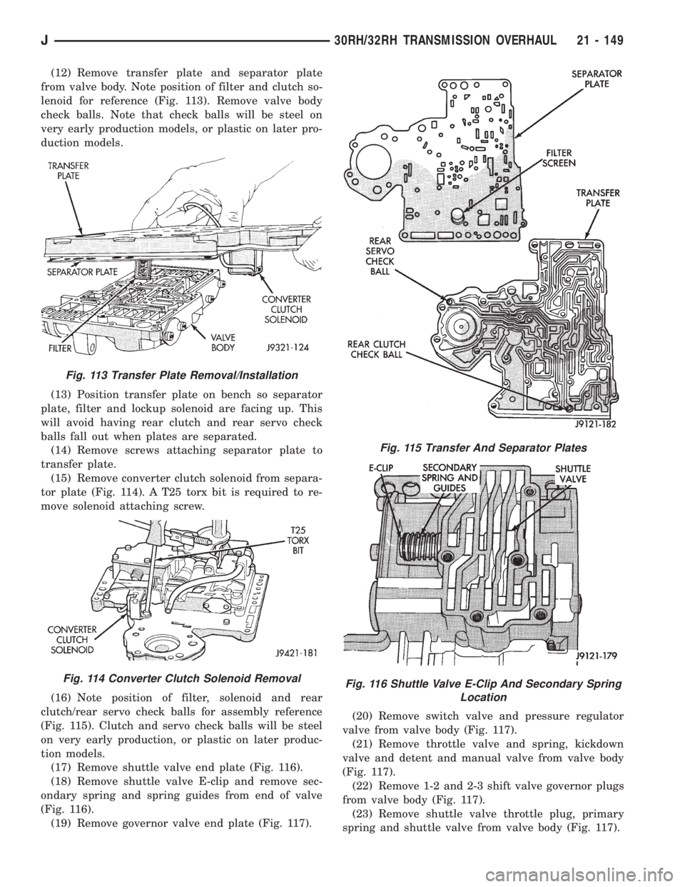
(12) Remove transfer plate and separator plate
from valve body. Note position of filter and clutch so-
lenoid for reference (Fig. 113). Remove valve body
check balls. Note that check balls will be steel on
very early production models, or plastic on later pro-
duction models.
(13) Position transfer plate on bench so separator
plate, filter and lockup solenoid are facing up. This
will avoid having rear clutch and rear servo check
balls fall out when plates are separated.
(14) Remove screws attaching separator plate to
transfer plate.
(15) Remove converter clutch solenoid from separa-
tor plate (Fig. 114). A T25 torx bit is required to re-
move solenoid attaching screw.
(16) Note position of filter, solenoid and rear
clutch/rear servo check balls for assembly reference
(Fig. 115). Clutch and servo check balls will be steel
on very early production, or plastic on later produc-
tion models.
(17) Remove shuttle valve end plate (Fig. 116).
(18) Remove shuttle valve E-clip and remove sec-
ondary spring and spring guides from end of valve
(Fig. 116).
(19) Remove governor valve end plate (Fig. 117).(20) Remove switch valve and pressure regulator
valve from valve body (Fig. 117).
(21) Remove throttle valve and spring, kickdown
valve and detent and manual valve from valve body
(Fig. 117).
(22) Remove 1-2 and 2-3 shift valve governor plugs
from valve body (Fig. 117).
(23) Remove shuttle valve throttle plug, primary
spring and shuttle valve from valve body (Fig. 117).
Fig. 113 Transfer Plate Removal/Installation
Fig. 114 Converter Clutch Solenoid Removal
Fig. 115 Transfer And Separator Plates
Fig. 116 Shuttle Valve E-Clip And Secondary Spring
Location
J30RH/32RH TRANSMISSION OVERHAUL 21 - 149