1995 JEEP CHEROKEE display
[x] Cancel search: displayPage 1243 of 2198
The throttle body has an air control passage that
provides air for the engine at idle (the throttle plate
is closed). The IAC motor pintle protrudes into the
air control passage and regulates air flow through it.
Based on various sensor inputs, the powertrain con-
trol module (PCM) adjusts engine idle speed by mov-
ing the IAC motor pintle in and out of the air control
passage. The IAC motor is positioned when the igni-
tion key is turned to the On position.
A (factory adjusted) set screw is used to mechani-
cally limit the position of the throttle body throttle
plate.Never attempt to adjust the engine idle
speed using this screw.All idle speed functions are
controlled by the PCM.
IGNITION COILÐPCM OUTPUT
System voltage is supplied to the ignition coil pos-
itive terminal. The powertrain control module (PCM)
operates the ignition coil.Base (initial) ignition
timing is not adjustable.The PCM adjusts ignition
timing to meet changing engine operating conditions.
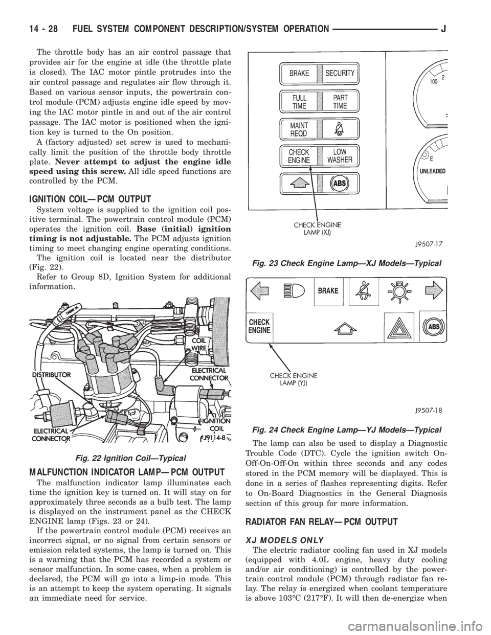
The ignition coil is located near the distributor
(Fig. 22).
Refer to Group 8D, Ignition System for additional
information.
MALFUNCTION INDICATOR LAMPÐPCM OUTPUT
The malfunction indicator lamp illuminates each
time the ignition key is turned on. It will stay on for
approximately three seconds as a bulb test. The lamp
is displayed on the instrument panel as the CHECK
ENGINE lamp (Figs. 23 or 24).
If the powertrain control module (PCM) receives an
incorrect signal, or no signal from certain sensors or
emission related systems, the lamp is turned on. This
is a warning that the PCM has recorded a system or
sensor malfunction. In some cases, when a problem is
declared, the PCM will go into a limp-in mode. This
is an attempt to keep the system operating. It signals
an immediate need for service.The lamp can also be used to display a Diagnostic
Trouble Code (DTC). Cycle the ignition switch On-
Off-On-Off-On within three seconds and any codes
stored in the PCM memory will be displayed. This is
done in a series of flashes representing digits. Refer
to On-Board Diagnostics in the General Diagnosis
section of this group for more information.
RADIATOR FAN RELAYÐPCM OUTPUT
XJ MODELS ONLY
The electric radiator cooling fan used in XJ models
(equipped with 4.0L engine, heavy duty cooling
and/or air conditioning) is controlled by the power-
train control module (PCM) through radiator fan re-
lay. The relay is energized when coolant temperature
is above 103ÉC (217ÉF). It will then de-energize when
Fig. 22 Ignition CoilÐTypical
Fig. 23 Check Engine LampÐXJ ModelsÐTypical
Fig. 24 Check Engine LampÐYJ ModelsÐTypical
14 - 28 FUEL SYSTEM COMPONENT DESCRIPTION/SYSTEM OPERATIONJ
Page 1256 of 2198
PCM SYSTEM SCHEMATICS
Powertrain control system schematics for the 2.5L
4-cylinder and 4.0L 6-cylinder engines are shown in
figures 29, 30, 31 and 32.
These schematics are displayed as a quick refer-
ence only. They are not intended to be all-inclusive.
Refer to the Wiring Diagrams section for detailed in-
formation.
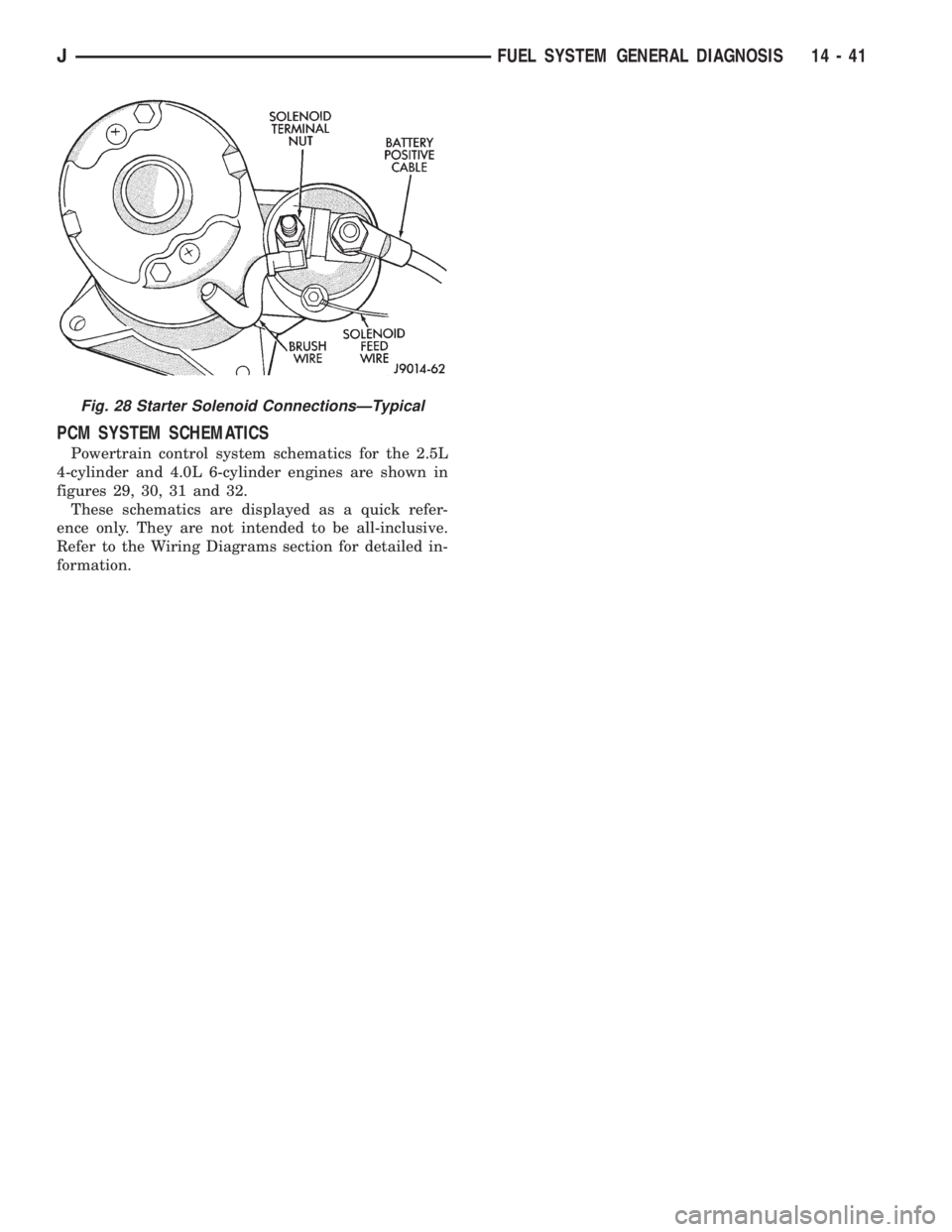
Fig. 28 Starter Solenoid ConnectionsÐTypical
JFUEL SYSTEM GENERAL DIAGNOSIS 14 - 41
Page 1263 of 2198
EXTENDED IDLE SWITCH TEST
OPTIONAL POLICE PACKAGE ONLY
OPERATION
The extended idle switch is used to raise the en-
gine idle speed to approximately 1000 rpm when the
shifter is in either the Park or Neutral position. A
rocker-type 2-wire switch (extended idle switch) is
mounted to the instrument panel.This switch is
available only with 4.0L engine when supplied
with the optional police package.
TESTING
The extended idle switch will control a ground cir-
cuit going to the powertrain control module (PCM).
When a ground signal (through this switch) has been
received at pin number 10 in the PCM, engine idle
speed will increase.
Bring the engine to normal operating temperature
and turn the extended idle switch to the ON position.
Engine speed should now increase to approximately
1000 rpm when the shifter is in either the Park or
Neutral position. If engine speed does not increase,
apply a good ground to pin number 10 at the PCM
using a small paper clip. Be careful not to damage
the wiring with the paper clip. If the engine speed
now increases, it can be assumed that the PCM is
functioning correctly. Check the instrument panel
mounted switch for a closed ground circuit when in
the ON position. If the engine speed will not increase
after applying a ground to pin number 10, replace
the PCM. Refer to Group 8W, Wiring Diagrams for
circuit and wiring information.
THROTTLE POSITION SENSOR (TPS) TEST
To perform a complete test of the sensor and its cir-
cuitry, refer to DRB scan tool and appropriate Pow-
ertrain Diagnostics Procedures manual. To test the
sensor only, refer to the following:
The throttle position sensor (TPS) can be tested
with a digital voltmeter. The center terminal of the
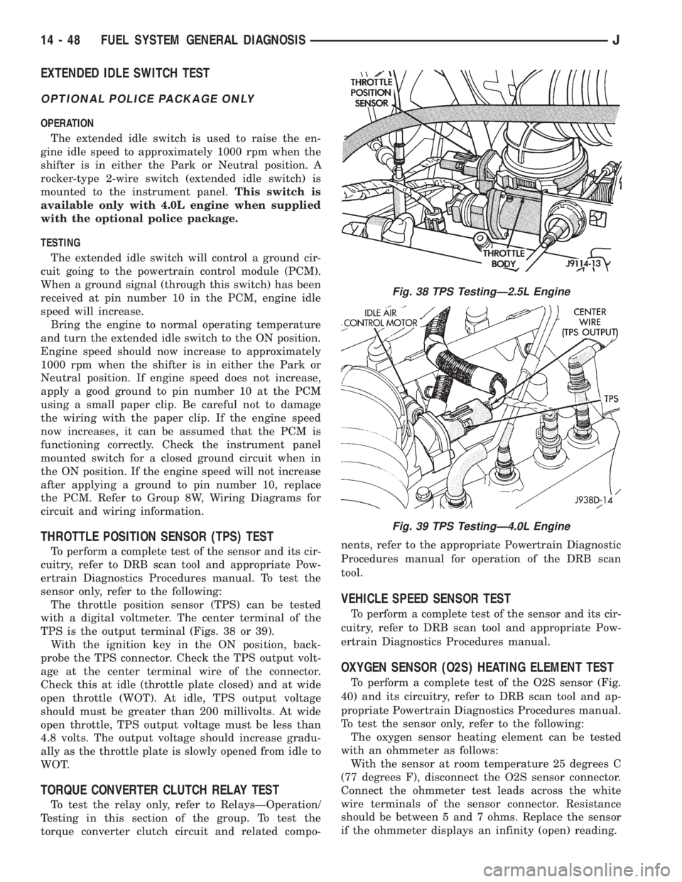
TPS is the output terminal (Figs. 38 or 39).
With the ignition key in the ON position, back-
probe the TPS connector. Check the TPS output volt-
age at the center terminal wire of the connector.
Check this at idle (throttle plate closed) and at wide
open throttle (WOT). At idle, TPS output voltage
should must be greater than 200 millivolts. At wide
open throttle, TPS output voltage must be less than
4.8 volts. The output voltage should increase gradu-
ally as the throttle plate is slowly opened from idle to
WOT.
TORQUE CONVERTER CLUTCH RELAY TEST
To test the relay only, refer to RelaysÐOperation/
Testing in this section of the group. To test the
torque converter clutch circuit and related compo-nents, refer to the appropriate Powertrain Diagnostic
Procedures manual for operation of the DRB scan
tool.
VEHICLE SPEED SENSOR TEST
To perform a complete test of the sensor and its cir-
cuitry, refer to DRB scan tool and appropriate Pow-
ertrain Diagnostics Procedures manual.
OXYGEN SENSOR (O2S) HEATING ELEMENT TEST
To perform a complete test of the O2S sensor (Fig.
40) and its circuitry, refer to DRB scan tool and ap-
propriate Powertrain Diagnostics Procedures manual.
To test the sensor only, refer to the following:
The oxygen sensor heating element can be tested
with an ohmmeter as follows:
With the sensor at room temperature 25 degrees C
(77 degrees F), disconnect the O2S sensor connector.
Connect the ohmmeter test leads across the white
wire terminals of the sensor connector. Resistance
should be between 5 and 7 ohms. Replace the sensor
if the ohmmeter displays an infinity (open) reading.
Fig. 38 TPS TestingÐ2.5L Engine
Fig. 39 TPS TestingÐ4.0L Engine
14 - 48 FUEL SYSTEM GENERAL DIAGNOSISJ
Page 1266 of 2198
(8) Disconnect jumper wires from relay and 12 Volt
power source.
If continuity or resistance tests did not pass, re-
place relay. If tests passed, refer to Group 8W, Wiring
Diagrams for additional circuit information. Also re-
fer to the appropriate Powertrain Diagnostic Proce-
dures manual for operation of the DRB scan tool.
STARTER MOTOR RELAY TEST
Refer to Group 8A, Battery/Starting/Charging/Sys-
tem Diagnostics, for starter motor relay testing.
FUEL INJECTOR TEST
To perform a complete test of the fuel injectors and
their circuitry, refer to DRB scan tool and appropri-
ate Powertrain Diagnostics Procedures manual. To
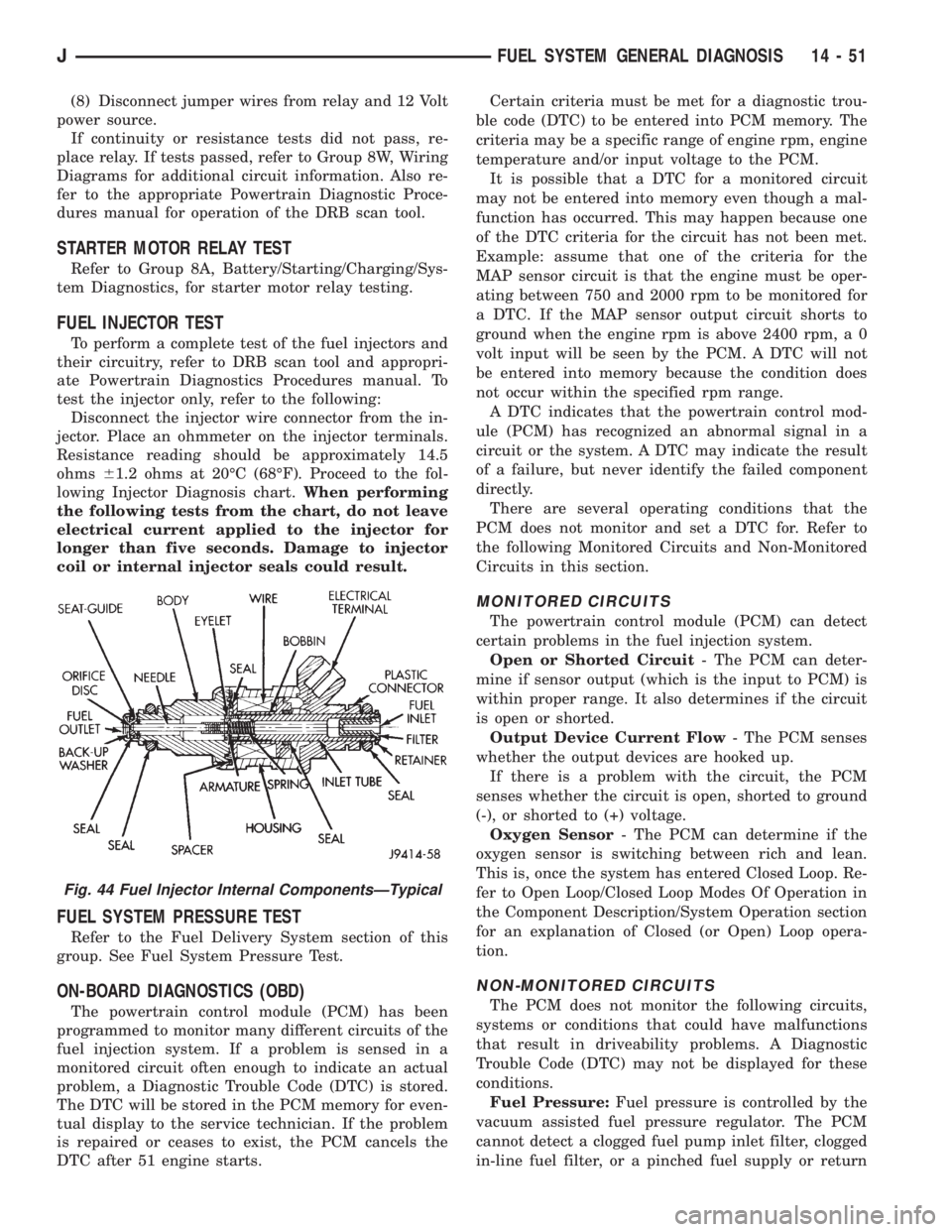
test the injector only, refer to the following:
Disconnect the injector wire connector from the in-
jector. Place an ohmmeter on the injector terminals.
Resistance reading should be approximately 14.5
ohms61.2 ohms at 20ÉC (68ÉF). Proceed to the fol-
lowing Injector Diagnosis chart.When performing
the following tests from the chart, do not leave
electrical current applied to the injector for
longer than five seconds. Damage to injector
coil or internal injector seals could result.
FUEL SYSTEM PRESSURE TEST
Refer to the Fuel Delivery System section of this
group. See Fuel System Pressure Test.
ON-BOARD DIAGNOSTICS (OBD)
The powertrain control module (PCM) has been
programmed to monitor many different circuits of the
fuel injection system. If a problem is sensed in a
monitored circuit often enough to indicate an actual
problem, a Diagnostic Trouble Code (DTC) is stored.
The DTC will be stored in the PCM memory for even-
tual display to the service technician. If the problem
is repaired or ceases to exist, the PCM cancels the
DTC after 51 engine starts.Certain criteria must be met for a diagnostic trou-
ble code (DTC) to be entered into PCM memory. The
criteria may be a specific range of engine rpm, engine
temperature and/or input voltage to the PCM.
It is possible that a DTC for a monitored circuit
may not be entered into memory even though a mal-
function has occurred. This may happen because one
of the DTC criteria for the circuit has not been met.
Example: assume that one of the criteria for the
MAP sensor circuit is that the engine must be oper-
ating between 750 and 2000 rpm to be monitored for
a DTC. If the MAP sensor output circuit shorts to
ground when the engine rpm is above 2400 rpm, a 0
volt input will be seen by the PCM. A DTC will not
be entered into memory because the condition does
not occur within the specified rpm range.
A DTC indicates that the powertrain control mod-
ule (PCM) has recognized an abnormal signal in a
circuit or the system. A DTC may indicate the result
of a failure, but never identify the failed component
directly.
There are several operating conditions that the
PCM does not monitor and set a DTC for. Refer to
the following Monitored Circuits and Non-Monitored
Circuits in this section.
MONITORED CIRCUITS
The powertrain control module (PCM) can detect
certain problems in the fuel injection system.
Open or Shorted Circuit- The PCM can deter-
mine if sensor output (which is the input to PCM) is
within proper range. It also determines if the circuit
is open or shorted.
Output Device Current Flow- The PCM senses
whether the output devices are hooked up.
If there is a problem with the circuit, the PCM
senses whether the circuit is open, shorted to ground
(-), or shorted to (+) voltage.
Oxygen Sensor- The PCM can determine if the
oxygen sensor is switching between rich and lean.
This is, once the system has entered Closed Loop. Re-
fer to Open Loop/Closed Loop Modes Of Operation in
the Component Description/System Operation section
for an explanation of Closed (or Open) Loop opera-
tion.
NON-MONITORED CIRCUITS
The PCM does not monitor the following circuits,
systems or conditions that could have malfunctions
that result in driveability problems. A Diagnostic
Trouble Code (DTC) may not be displayed for these
conditions.
Fuel Pressure:Fuel pressure is controlled by the
vacuum assisted fuel pressure regulator. The PCM
cannot detect a clogged fuel pump inlet filter, clogged
in-line fuel filter, or a pinched fuel supply or return
Fig. 44 Fuel Injector Internal ComponentsÐTypical
JFUEL SYSTEM GENERAL DIAGNOSIS 14 - 51
Page 1268 of 2198
line. However, these could result in a rich or lean
condition causing an oxygen sensor DTC to be stored
in the PCM.
Secondary Ignition Circuit:The PCM cannot
detect an inoperative ignition coil, fouled or worn
spark plugs, ignition cross firing, or open circuited
spark plug cables.
Engine Timing:The PCM cannot detect an incor-
rectly indexed timing chain, camshaft sprocket or
crankshaft sprocket. The PCM also cannot detect an
incorrectly indexed distributor. However, these could
result in a rich or lean condition causing an oxygen
sensor DTC to be stored in the PCM.
Cylinder Compression:The PCM cannot detect
uneven, low, or high engine cylinder compression.
Exhaust System:The PCM cannot detect a
plugged, restricted or leaking exhaust system.
Fuel Injector Malfunctions:The PCM cannot de-
termine if the fuel injector is clogged, or the wrong
injector is installed. However, these could result in a
rich or lean condition causing an oxygen sensor DTC
to be stored in the PCM.
Excessive Oil Consumption:Although the PCM
monitors exhaust stream oxygen content through ox-
ygen sensor (closed loop), it cannot determine exces-
sive oil consumption.
Throttle Body Air Flow:The PCM cannot detect
a clogged or restricted air cleaner inlet or air cleaner
element.
Evaporative System:The PCM will not detect a
restricted, plugged or loaded EVAP canister.
Vacuum Assist:Leaks or restrictions in the vac-
uum circuits of vacuum assisted engine control sys-
tem devices are not monitored by the PCM. However,
a vacuum leak at the MAP sensor will be monitored
and a diagnostic trouble code (DTC) will be gener-
ated by the PCM.
Powertrain Control Module (PCM) System
Ground:The PCM cannot determine a poor system
ground. However, a DTC may be generated as a re-
sult of this condition.
Powertrain Control Module (PCM) Connector
Engagement:The PCM cannot determine spread or
damaged connector pins. However, a DTC may be
generated as a result of this condition.
HIGH AND LOW LIMITS
The powertrain control module (PCM) compares in-
put signal voltages from each input device. It will es-
tablish high and low limits that are programmed into
it for that device. If the input voltage is not within
specifications and other Diagnostic Trouble Code
(DTC) criteria are met, a DTC will be stored in mem-
ory. Other DTC criteria might include engine rpm
limits or input voltages from other sensors or
switches. The other inputs might have to be sensed
by the PCM when it senses a high or low input volt-
age from the control system device in question.
ACCESSING DIAGNOSTIC TROUBLE CODES
A stored diagnostic trouble code (DTC) can be dis-
played by cycling the ignition key On-Off-On-Off-On
within three seconds and observing the malfunction
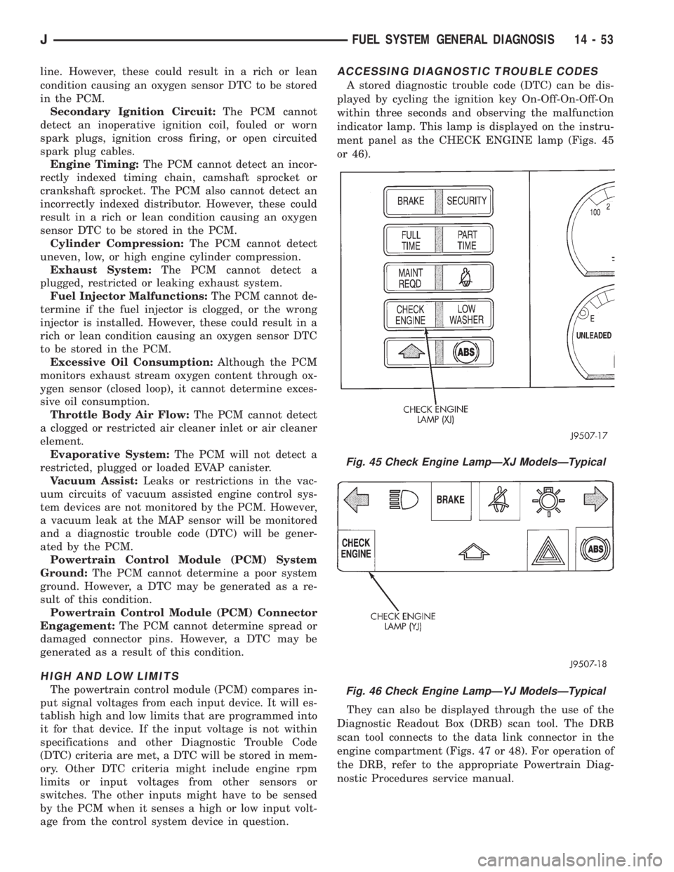
indicator lamp. This lamp is displayed on the instru-
ment panel as the CHECK ENGINE lamp (Figs. 45
or 46).
They can also be displayed through the use of the
Diagnostic Readout Box (DRB) scan tool. The DRB
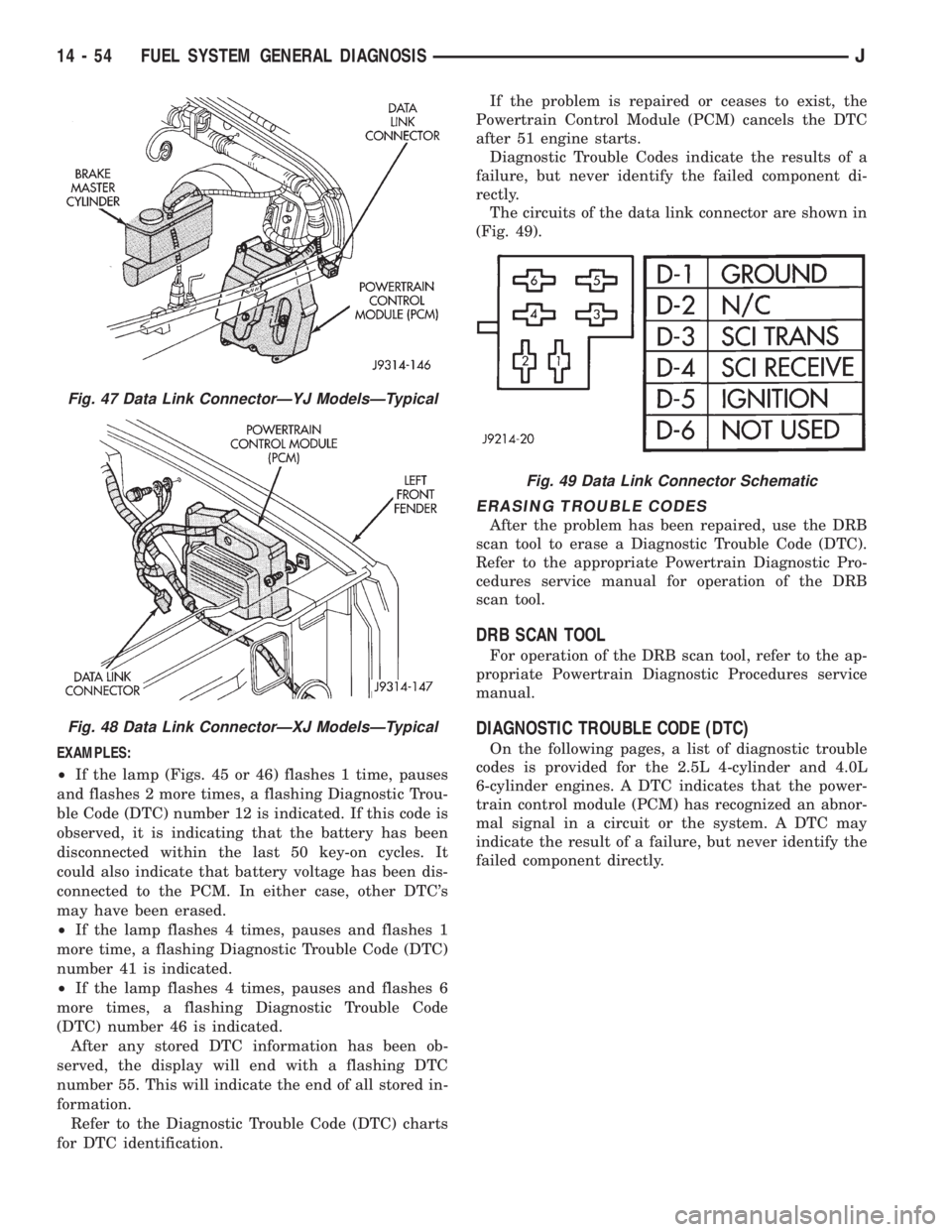
scan tool connects to the data link connector in the
engine compartment (Figs. 47 or 48). For operation of
the DRB, refer to the appropriate Powertrain Diag-
nostic Procedures service manual.
Fig. 45 Check Engine LampÐXJ ModelsÐTypical
Fig. 46 Check Engine LampÐYJ ModelsÐTypical
JFUEL SYSTEM GENERAL DIAGNOSIS 14 - 53
Page 1269 of 2198
EXAMPLES:
²If the lamp (Figs. 45 or 46) flashes 1 time, pauses
and flashes 2 more times, a flashing Diagnostic Trou-
ble Code (DTC) number 12 is indicated. If this code is
observed, it is indicating that the battery has been
disconnected within the last 50 key-on cycles. It
could also indicate that battery voltage has been dis-
connected to the PCM. In either case, other DTC's
may have been erased.
²If the lamp flashes 4 times, pauses and flashes 1
more time, a flashing Diagnostic Trouble Code (DTC)
number 41 is indicated.
²If the lamp flashes 4 times, pauses and flashes 6
more times, a flashing Diagnostic Trouble Code
(DTC) number 46 is indicated.
After any stored DTC information has been ob-
served, the display will end with a flashing DTC
number 55. This will indicate the end of all stored in-
formation.
Refer to the Diagnostic Trouble Code (DTC) charts
for DTC identification.If the problem is repaired or ceases to exist, the
Powertrain Control Module (PCM) cancels the DTC
after 51 engine starts.
Diagnostic Trouble Codes indicate the results of a
failure, but never identify the failed component di-
rectly.
The circuits of the data link connector are shown in
(Fig. 49).
ERASING TROUBLE CODES
After the problem has been repaired, use the DRB
scan tool to erase a Diagnostic Trouble Code (DTC).
Refer to the appropriate Powertrain Diagnostic Pro-
cedures service manual for operation of the DRB
scan tool.
DRB SCAN TOOL
For operation of the DRB scan tool, refer to the ap-
propriate Powertrain Diagnostic Procedures service
manual.
DIAGNOSTIC TROUBLE CODE (DTC)
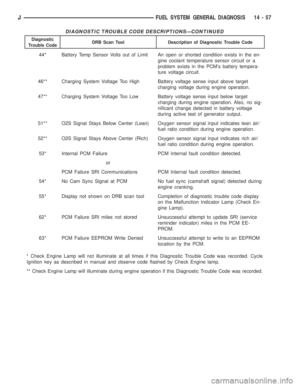
On the following pages, a list of diagnostic trouble
codes is provided for the 2.5L 4-cylinder and 4.0L
6-cylinder engines. A DTC indicates that the power-
train control module (PCM) has recognized an abnor-
mal signal in a circuit or the system. A DTC may
indicate the result of a failure, but never identify the
failed component directly.
Fig. 47 Data Link ConnectorÐYJ ModelsÐTypical
Fig. 48 Data Link ConnectorÐXJ ModelsÐTypical
Fig. 49 Data Link Connector Schematic
14 - 54 FUEL SYSTEM GENERAL DIAGNOSISJ
Page 1272 of 2198
DIAGNOSTIC TROUBLE CODE DESCRIPTIONSÐCONTINUED
Diagnostic
Trouble CodeDRB Scan Tool Description of Diagnostic Trouble Code
44* Battery Temp Sensor Volts out of Limit An open or shorted condition exists in the en-
gine coolant temperature sensor circuit or a
problem exists in the PCM's battery tempera-
ture voltage circuit.
46** Charging System Voltage Too High Battery voltage sense input above target
charging voltage during engine operation.
47** Charging System Voltage Too Low Battery voltage sense input below target
charging during engine operation. Also, no sig-
nificant change detected in battery voltage
during active test of generator output.
51** O2S Signal Stays Below Center (Lean) Oxygen sensor signal input indicates lean air/
fuel ratio condition during engine operation.
52** O2S Signal Stays Above Center (Rich) Oxygen sensor signal input indicates rich air/
fuel ratio condition during engine operation.
53* Internal PCM Failure PCM Internal fault condition detected.
or
PCM Failure SRI Communications PCM Internal fault condition detected.
54* No Cam Sync Signal at PCM No fuel sync (camshaft signal) detected during
engine cranking.
55* Display not shown on DRB scan tool Completion of diagnostic trouble code display
on the Malfunction Indicator Lamp (Check En-
gine Lamp).
62* PCM Failure SRI miles not stored Unsuccessful attempt to update SRI (service
reminder indicator) miles in the PCM EE-
PROM.
63* PCM Failure EEPROM Write Denied Unsuccessful attempt to write to an EEPROM
location by the PCM.
* Check Engine Lamp will not illuminate at all times if this Diagnostic Trouble Code was recorded. Cycle
Ignition key as described in manual and observe code flashed by Check Engine lamp.
** Check Engine Lamp will illuminate during engine operation if this Diagnostic Trouble Code was recorded.
JFUEL SYSTEM GENERAL DIAGNOSIS 14 - 57
Page 1569 of 2198
SPEED SENSOR
SPEED SENSOR TESTING
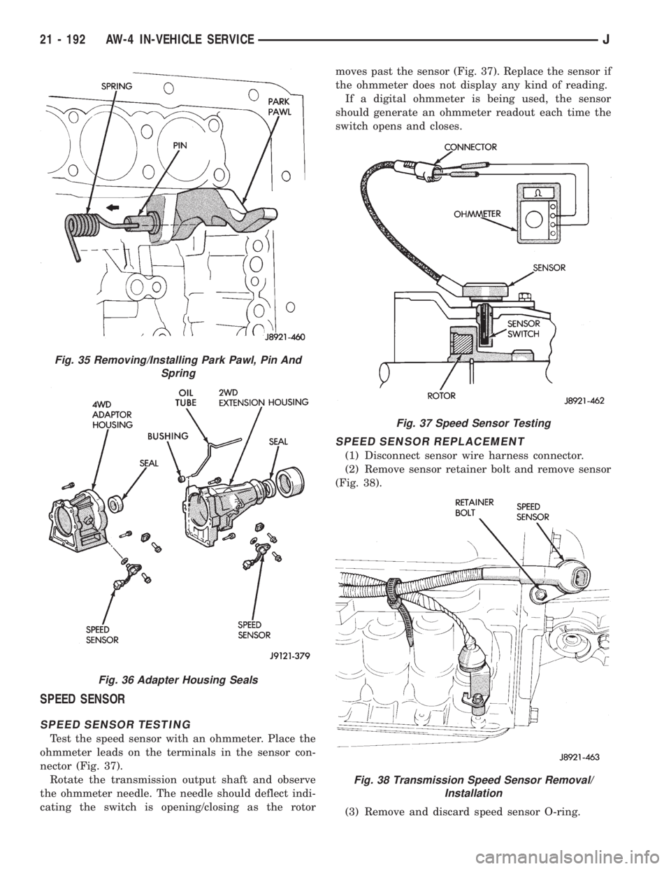
Test the speed sensor with an ohmmeter. Place the
ohmmeter leads on the terminals in the sensor con-
nector (Fig. 37).
Rotate the transmission output shaft and observe
the ohmmeter needle. The needle should deflect indi-
cating the switch is opening/closing as the rotormoves past the sensor (Fig. 37). Replace the sensor if
the ohmmeter does not display any kind of reading.
If a digital ohmmeter is being used, the sensor
should generate an ohmmeter readout each time the
switch opens and closes.
SPEED SENSOR REPLACEMENT
(1) Disconnect sensor wire harness connector.
(2) Remove sensor retainer bolt and remove sensor
(Fig. 38).
(3) Remove and discard speed sensor O-ring.
Fig. 35 Removing/Installing Park Pawl, Pin And
Spring
Fig. 36 Adapter Housing Seals
Fig. 37 Speed Sensor Testing
Fig. 38 Transmission Speed Sensor Removal/
Installation
21 - 192 AW-4 IN-VEHICLE SERVICEJ