1995 JEEP CHEROKEE display
[x] Cancel search: displayPage 3 of 2198
CLASSIFICATION OF LUBRICANTS
Lubricating fluids and chassis lubricants are clas-
sified according to standards recommended by the:
²Society of Automotive Engineers (SAE)
²American Petroleum Institute (API)
²National Lubricating Grease Institute (NLGI)
ENGINE OIL
API CERTIFICATION MARK
For maximum engine protection during all driving
conditions, install an engine oil that contains the API
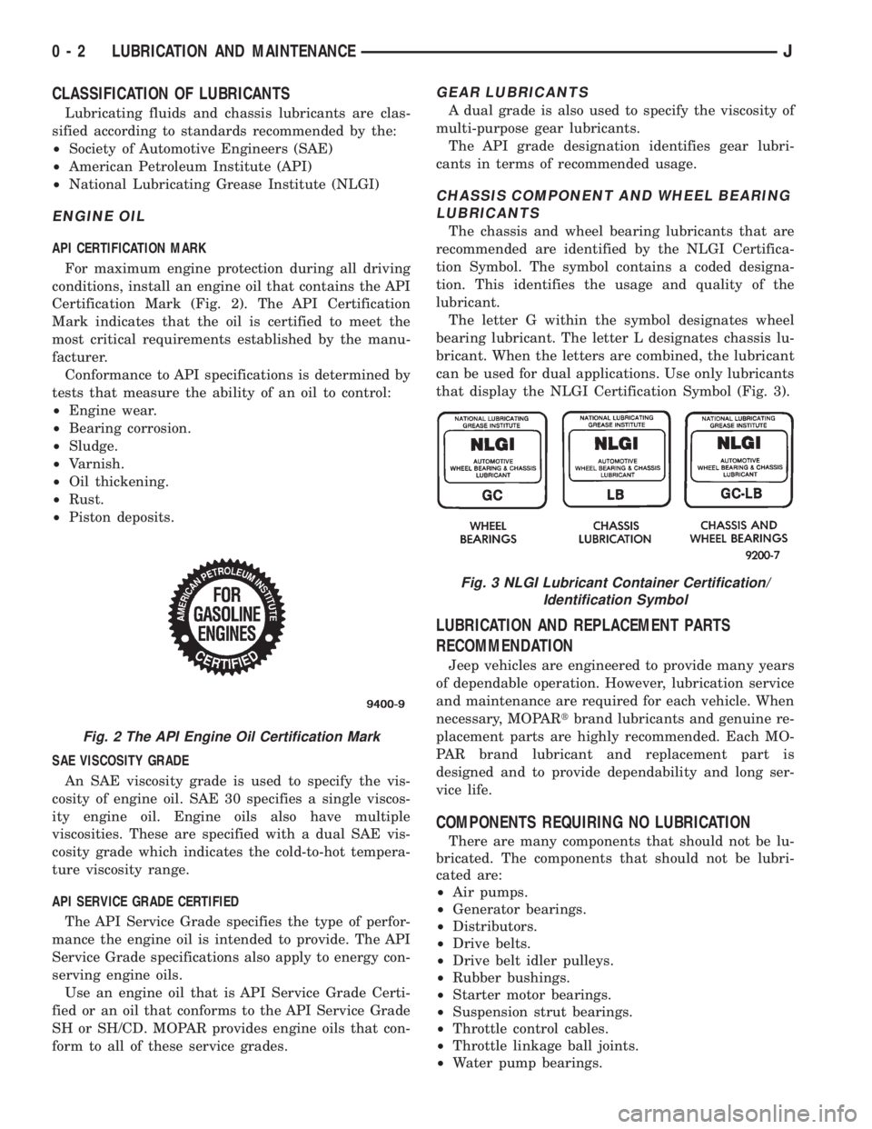
Certification Mark (Fig. 2). The API Certification
Mark indicates that the oil is certified to meet the
most critical requirements established by the manu-
facturer.
Conformance to API specifications is determined by
tests that measure the ability of an oil to control:
²Engine wear.
²Bearing corrosion.
²Sludge.
²Varnish.
²Oil thickening.
²Rust.
²Piston deposits.
SAE VISCOSITY GRADE
An SAE viscosity grade is used to specify the vis-
cosity of engine oil. SAE 30 specifies a single viscos-
ity engine oil. Engine oils also have multiple
viscosities. These are specified with a dual SAE vis-
cosity grade which indicates the cold-to-hot tempera-
ture viscosity range.
API SERVICE GRADE CERTIFIED
The API Service Grade specifies the type of perfor-
mance the engine oil is intended to provide. The API
Service Grade specifications also apply to energy con-
serving engine oils.
Use an engine oil that is API Service Grade Certi-
fied or an oil that conforms to the API Service Grade
SH or SH/CD. MOPAR provides engine oils that con-
form to all of these service grades.
GEAR LUBRICANTS
A dual grade is also used to specify the viscosity of
multi-purpose gear lubricants.
The API grade designation identifies gear lubri-
cants in terms of recommended usage.
CHASSIS COMPONENT AND WHEEL BEARING
LUBRICANTS
The chassis and wheel bearing lubricants that are
recommended are identified by the NLGI Certifica-
tion Symbol. The symbol contains a coded designa-
tion. This identifies the usage and quality of the
lubricant.
The letter G within the symbol designates wheel
bearing lubricant. The letter L designates chassis lu-
bricant. When the letters are combined, the lubricant
can be used for dual applications. Use only lubricants
that display the NLGI Certification Symbol (Fig. 3).
LUBRICATION AND REPLACEMENT PARTS
RECOMMENDATION
Jeep vehicles are engineered to provide many years
of dependable operation. However, lubrication service
and maintenance are required for each vehicle. When
necessary, MOPARtbrand lubricants and genuine re-
placement parts are highly recommended. Each MO-
PAR brand lubricant and replacement part is
designed and to provide dependability and long ser-
vice life.
COMPONENTS REQUIRING NO LUBRICATION
There are many components that should not be lu-
bricated. The components that should not be lubri-
cated are:
²Air pumps.
²Generator bearings.
²Distributors.
²Drive belts.
²Drive belt idler pulleys.
²Rubber bushings.
²Starter motor bearings.
²Suspension strut bearings.
²Throttle control cables.
²Throttle linkage ball joints.
²Water pump bearings.
Fig. 2 The API Engine Oil Certification Mark
Fig. 3 NLGI Lubricant Container Certification/
Identification Symbol
0 - 2 LUBRICATION AND MAINTENANCEJ
Page 140 of 2198
ABS BRAKE DIAGNOSIS
INDEX
page page
ABS Diagnostic Connector................... 3
ABS Warning Light Display................... 3
Antilock ECU and Hcu Diagnosis............... 3
DRB Scan Tool............................ 3General Information........................ 3
Normal Operating Conditions.................. 3
Wheel/Tire Size and Input Signals.............. 3
GENERAL INFORMATION
The DRB scan tool is required for ABS diagnosis.
The scan tool is used to identify ABS circuit faults.
Once a faulty circuit has been identified, refer to
the appropriate chassis/body diagnostic manual for
individual component testing.
ABS WARNING LIGHT DISPLAY
The amber antilock light illuminates at startup as
part of the system self check feature. The light illu-
minates for 2-3 seconds then goes off as part of the
normal check routine.
An ABS circuit fault is indicated when the amber
light remains on after startup, or illuminates during
vehicle operation.
Verify that a fault is actually related to the ABS
system before making repairs. For example, if the
red warning illuminates but the ABS light does not,
the problem is related to a service brake component
and not the ABS system. Or, if neither light illumi-
nates but a brake problem is noted, again, the prob-
lem is with a service brake component and not with
the ABS system.
ABS DIAGNOSTIC CONNECTOR
The ABS diagnostic connector is inside the vehicle.
The connector is the access point for the DRB scan tool.
On XJ models, the connector is located under the
instrument panel to the right of the steering column.
On some models, the connecter may be tucked under
the carpeting on the transmission tunnel. The con-
necter is a black, 6-way type.
On YJ models, the connector is under the instru-
ment panel by the the driver side kick panel. The
connecter is a black, 6 or 8-way type.
The DRB scan tool kit contains adapter cords for
both types of connecter. Use the appropriate cord for
test hookup.
DRB SCAN TOOL
ABS diagnosis is performed with the DRB scan tool.
Refer to the DRB scan tool manual for test hookup and
procedures. Diagnosis information is provided in the ap-
propriate chassis/body diagnostic manual.
WHEEL/TIRE SIZE AND INPUT SIGNALS
Antilock system operation is dependant on accurate
signals from the wheel speed sensors. Ideally, the ve-
hicle wheels and tires should all be the same size
and type. However, the Jeep ABS system is designed
to operate with a compact spare tire installed.
NORMAL OPERATING CONDITIONS
Sound Levels
The hydraulic control unit pump and solenoid valves
may produce some sound as they cycle on and off. This
is a normal condition and should not be mistaken for
faulty operation. Under most conditions, pump and so-
lenoid valve operating sounds will not be audible.
Vehicle Response In Antilock Mode
During antilock braking, the hydraulic control unit
solenoid valves cycle rapidly in response to antilock
electronic control unit signals.
The driver will experience a pulsing sensation
within the vehicle as the solenoids decrease, hold, or
increase pressure as needed. Brake pedal pulsing will
also be noted and is anormal condition.
Steering Response
A modest amount of steering input is required dur-
ing extremely high deceleration braking, or when
braking on differing traction surfaces. An example of
differing traction surfaces would be when the left
side wheels are on ice and the right side wheels are
on dry pavement.
Owner Induced Faults
Driving away with the parking brakes still applied
will cause warning light illumination. Pumping the
brake pedal will also generate a system fault and in-
terfere with ABS system operation.
ANTILOCK ECU AND HCU DIAGNOSIS
An ECU or HCU fault can only be determined
through testing with the DRB scan tool. Do not re-
place either component unless a fault is actually in-
dicated.
JABS BRAKE DIAGNOSIS 5 - 3
Page 148 of 2198
bubbles that are distributed throughout the hydrau-
lic system. This will make extra bleeding operations
necessary.
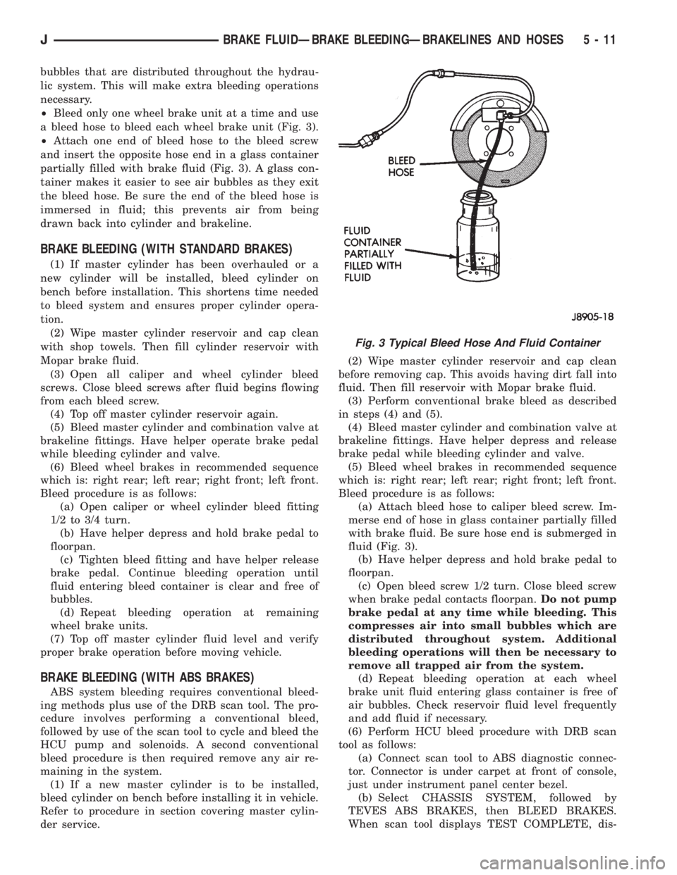
²Bleed only one wheel brake unit at a time and use
a bleed hose to bleed each wheel brake unit (Fig. 3).
²Attach one end of bleed hose to the bleed screw
and insert the opposite hose end in a glass container
partially filled with brake fluid (Fig. 3). A glass con-
tainer makes it easier to see air bubbles as they exit
the bleed hose. Be sure the end of the bleed hose is
immersed in fluid; this prevents air from being
drawn back into cylinder and brakeline.
BRAKE BLEEDING (WITH STANDARD BRAKES)
(1) If master cylinder has been overhauled or a
new cylinder will be installed, bleed cylinder on
bench before installation. This shortens time needed
to bleed system and ensures proper cylinder opera-
tion.
(2) Wipe master cylinder reservoir and cap clean
with shop towels. Then fill cylinder reservoir with
Mopar brake fluid.
(3) Open all caliper and wheel cylinder bleed
screws. Close bleed screws after fluid begins flowing
from each bleed screw.
(4) Top off master cylinder reservoir again.
(5) Bleed master cylinder and combination valve at
brakeline fittings. Have helper operate brake pedal
while bleeding cylinder and valve.
(6) Bleed wheel brakes in recommended sequence
which is: right rear; left rear; right front; left front.
Bleed procedure is as follows:
(a) Open caliper or wheel cylinder bleed fitting
1/2 to 3/4 turn.
(b) Have helper depress and hold brake pedal to
floorpan.
(c) Tighten bleed fitting and have helper release
brake pedal. Continue bleeding operation until
fluid entering bleed container is clear and free of
bubbles.
(d) Repeat bleeding operation at remaining
wheel brake units.
(7) Top off master cylinder fluid level and verify
proper brake operation before moving vehicle.
BRAKE BLEEDING (WITH ABS BRAKES)
ABS system bleeding requires conventional bleed-
ing methods plus use of the DRB scan tool. The pro-
cedure involves performing a conventional bleed,
followed by use of the scan tool to cycle and bleed the
HCU pump and solenoids. A second conventional
bleed procedure is then required remove any air re-
maining in the system.
(1) If a new master cylinder is to be installed,
bleed cylinder on bench before installing it in vehicle.
Refer to procedure in section covering master cylin-
der service.(2) Wipe master cylinder reservoir and cap clean
before removing cap. This avoids having dirt fall into
fluid. Then fill reservoir with Mopar brake fluid.
(3) Perform conventional brake bleed as described
in steps (4) and (5).
(4) Bleed master cylinder and combination valve at
brakeline fittings. Have helper depress and release
brake pedal while bleeding cylinder and valve.
(5) Bleed wheel brakes in recommended sequence
which is: right rear; left rear; right front; left front.
Bleed procedure is as follows:
(a) Attach bleed hose to caliper bleed screw. Im-
merse end of hose in glass container partially filled
with brake fluid. Be sure hose end is submerged in
fluid (Fig. 3).
(b) Have helper depress and hold brake pedal to
floorpan.
(c) Open bleed screw 1/2 turn. Close bleed screw
when brake pedal contacts floorpan.Do not pump
brake pedal at any time while bleeding. This
compresses air into small bubbles which are
distributed throughout system. Additional
bleeding operations will then be necessary to
remove all trapped air from the system.
(d) Repeat bleeding operation at each wheel
brake unit fluid entering glass container is free of
air bubbles. Check reservoir fluid level frequently
and add fluid if necessary.
(6) Perform HCU bleed procedure with DRB scan
tool as follows:
(a) Connect scan tool to ABS diagnostic connec-
tor. Connector is under carpet at front of console,
just under instrument panel center bezel.
(b) Select CHASSIS SYSTEM, followed by
TEVES ABS BRAKES, then BLEED BRAKES.
When scan tool displays TEST COMPLETE, dis-
Fig. 3 Typical Bleed Hose And Fluid Container
JBRAKE FLUIDÐBRAKE BLEEDINGÐBRAKELINES AND HOSES 5 - 11
Page 149 of 2198
connect scan tool and proceed to next step.
(7)Repeatconventional bleed procedure described
in steps (4) and (5).
(8) Top off master cylinder fluid level and verify
proper brake operation before moving vehicle.
BRAKELINES AND HOSES
Metal brakelines and rubber brake hoses should be
inspected periodically and replaced if damaged.
Rubber brake hoses should be replaced if cut,
cracked, swollen, or leaking. Rubber hoses must be
replaced as they are not repairable.
Steel brakelines should be inspected any time the
vehicle is in for normal maintenance. This is impor-
tant on high mileage vehicles. It is especially impor-
tant when the vehicle is operated on roads that are
salted during winter months.
Heavily rusted/corroded brake rotors, drums,
support plates, and brakelines should be
cleaned and carefully inspected. Heavy rust
buildup can hide severe damage to a compo-
nent. Severely rusted parts should be replaced
if condition is suspect.
BRAKELINE CHARTS
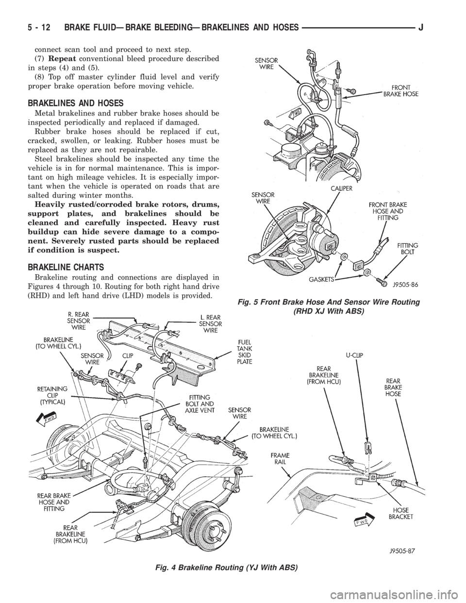
Brakeline routing and connections are displayed in
Figures 4 through 10. Routing for both right hand drive
(RHD) and left hand drive (LHD) models is provided.
Fig. 4 Brakeline Routing (YJ With ABS)
Fig. 5 Front Brake Hose And Sensor Wire Routing
(RHD XJ With ABS)
5 - 12 BRAKE FLUIDÐBRAKE BLEEDINGÐBRAKELINES AND HOSESJ
Page 229 of 2198
DIAGNOSIS
INDEX
page page
DRB Scan Tool............................ 5
On-Board Diagnostics (OBD).................. 4Preliminary Checks......................... 5
ON-BOARD DIAGNOSTICS (OBD)
FOR CERTAIN COOLING SYSTEM
COMPONENTS
The powertrain control module (PCM) has been
programmed to monitor the certain following cooling
system components:
²If the engine has remained cool for too long a pe-
riod, such as with a stuck open thermostat, a Diag-
nostic Trouble Code (DTC) number 17 can be
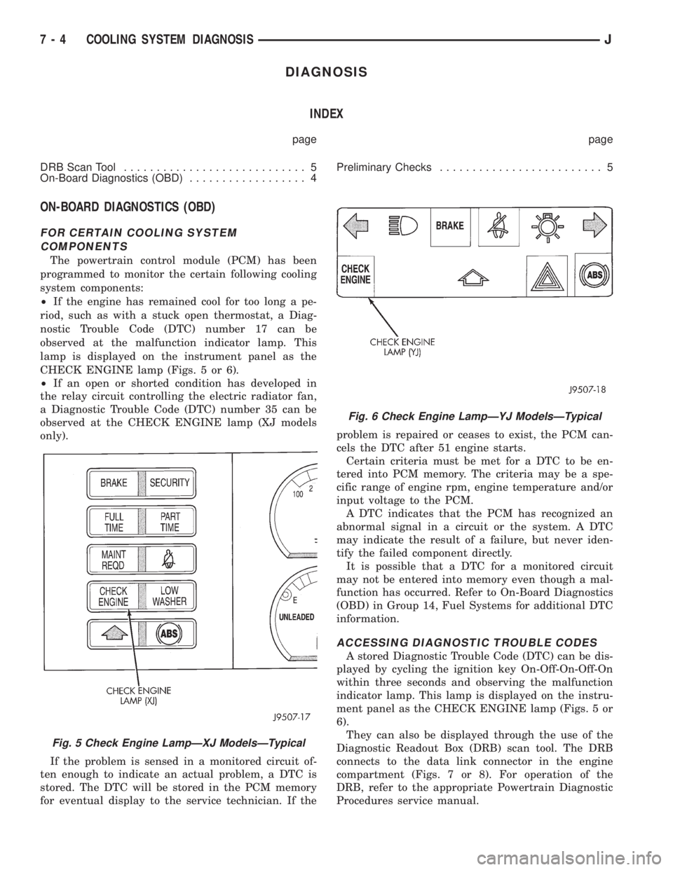
observed at the malfunction indicator lamp. This
lamp is displayed on the instrument panel as the
CHECK ENGINE lamp (Figs. 5 or 6).
²If an open or shorted condition has developed in
the relay circuit controlling the electric radiator fan,
a Diagnostic Trouble Code (DTC) number 35 can be
observed at the CHECK ENGINE lamp (XJ models
only).
If the problem is sensed in a monitored circuit of-
ten enough to indicate an actual problem, a DTC is
stored. The DTC will be stored in the PCM memory
for eventual display to the service technician. If theproblem is repaired or ceases to exist, the PCM can-
cels the DTC after 51 engine starts.
Certain criteria must be met for a DTC to be en-
tered into PCM memory. The criteria may be a spe-
cific range of engine rpm, engine temperature and/or
input voltage to the PCM.
A DTC indicates that the PCM has recognized an
abnormal signal in a circuit or the system. A DTC
may indicate the result of a failure, but never iden-
tify the failed component directly.
It is possible that a DTC for a monitored circuit
may not be entered into memory even though a mal-
function has occurred. Refer to On-Board Diagnostics
(OBD) in Group 14, Fuel Systems for additional DTC
information.
ACCESSING DIAGNOSTIC TROUBLE CODES
A stored Diagnostic Trouble Code (DTC) can be dis-
played by cycling the ignition key On-Off-On-Off-On
within three seconds and observing the malfunction
indicator lamp. This lamp is displayed on the instru-
ment panel as the CHECK ENGINE lamp (Figs. 5 or
6).
They can also be displayed through the use of the
Diagnostic Readout Box (DRB) scan tool. The DRB
connects to the data link connector in the engine
compartment (Figs. 7 or 8). For operation of the
DRB, refer to the appropriate Powertrain Diagnostic
Procedures service manual.
Fig. 5 Check Engine LampÐXJ ModelsÐTypical
Fig. 6 Check Engine LampÐYJ ModelsÐTypical
7 - 4 COOLING SYSTEM DIAGNOSISJ
Page 230 of 2198

EXAMPLES:
²If the lamp (Figs. 5 or 6) flashes 1 time, pauses
and flashes 2 more times, a flashing Diagnostic Trou-
ble Code (DTC) number 12 is indicated. If this code is
observed, it is indicating that the battery has been
disconnected within the last 50 key-on cycles. It
could also indicate that battery voltage has been dis-
connected to the PCM. In either case, other DTC's
may have been erased.
²If the lamp flashes 1 time, pauses and flashes 7
more times, a flashing Diagnostic Trouble Code
(DTC) number 17 is indicated.
²If the lamp flashes 3 times, pauses and flashes 5
more times, a flashing Diagnostic Trouble Code
(DTC) number 35 is indicated.
After any stored DTC information has been ob-
served, the display will end with a flashing DTC
number 55. This will indicate the end of all stored in-
formation.
ERASING TROUBLE CODES
After the problem has been repaired, the DRB scan
tool must be used to erase a DTC. Refer to the ap-
propriate Powertrain Diagnostic Procedures service
manual for operation of the DRB scan tool.
DRB SCAN TOOL
For operation of the DRB scan tool, refer to the ap-
propriate Powertrain Diagnostic Procedures service
manual.
PRELIMINARY CHECKS
ENGINE COOLING SYSTEM OVERHEATING
Establish what driving conditions caused the com-
plaint. Abnormal loads on the cooling system such as
the following may be the cause.
1. PROLONGED IDLE, VERY HIGH AMBIENT
TEMPERATURE, SLIGHT TAIL WIND AT IDLE,
SLOW TRAFFIC, TRAFFIC JAMS, HIGH
SPEED, OR STEEP GRADES:
Driving techniques that avoid overheating are:
²Idle with A/C off when temperature gauge is at
end of normal range.
²Increasing engine speed for more air flow is recom-
mended.
2. TRAILER TOWING:
Consult Trailer Towing section of owners manual.
Do not exceed limits.
3. AIR CONDITIONING; ADD-ON OR AFTER
MARKET:
A maximum cooling package should have been or-
dered with vehicle if add-on or after market A/C is
installed. If not, maximum cooling system compo-
nents should be installed for model involved per
manufacturer's specifications.
4. RECENT SERVICE OR ACCIDENT REPAIR:
Determine if any recent service has been performed
on vehicle that may effect cooling system. This may
be:
²Engine adjustments (incorrect timing)
²Slipping engine accessory drive belt(s)
²Brakes (possibly dragging)
²Changed parts (incorrect water pump rotating in
wrong direction)
²Reconditioned radiator or cooling system refilling
(possibly under-filled or air trapped in system).
If investigation reveals none of the previous
items as a cause for an engine overheating com-
plaint, refer to following Cooling System Diag-
nosis charts.
These charts are to be used as a quick-reference
only. Refer to the group text for information.
Fig. 7 Data Link ConnectorÐXJ ModelsÐTypical
Fig. 8 Data Link ConnectorÐYJ ModelsÐTypical
JCOOLING SYSTEM DIAGNOSIS 7 - 5
Page 260 of 2198
(5) Be sure that the air conditioner (if equipped) is
turned off.
WARNING: USE EXTREME CAUTION WHEN THE
ENGINE IS OPERATING. DO NOT STAND IN A DI-
RECT LINE WITH THE FAN. DO NOT PUT YOUR
HANDS NEAR THE PULLEYS, BELTS OR FAN. DO
NOT WEAR LOOSE CLOTHING.
(6) Start the engine and operate at 2400 rpm.
Within ten minutes the air temperature (indicated on
the dial thermometer) should be up to 88É C (190É F).
Fan driveengagementshould have started to occur
at between 74É to 82É C (165É to 180É F). Engage-
ment is distinguishable by a definiteincreasein fan
flow noise (roaring). The timing light also will indi-
cate an increase in the speed of the fan.
(7) When the air temperature reaches 88É C (190É
F), remove the plastic sheet. Fan drivedisengage-
mentshould have started to occur at between 57É to
79É C (135É to 175É F). A definitedecreaseof fan
flow noise (roaring) should be noticed. If not, replace
the defective viscous fan drive unit.
VISCOUS FAN DRIVE REMOVAL/INSTALLATION
Refer to the previous section on Cooling System
Fan for removal and installation procedures of the
viscous drive unit.
Viscous Fan Drive Fluid Pump Out Require-
ment:After installing anewviscous fan drive, bring
the engine speed up to approximately 2000 rpm and
hold for approximately two minutes. This will ensure
proper fluid distribution within the drive.
AUXILIARY ELECTRIC COOLING FANÐXJ MODELS
WITH 4.0L 6-CYLINDER ENGINE
OPERATION
XJ models equipped with a 4.0L 6-cylinder engine
may also have an auxiliary electrical cooling fan.
This is with models that have air conditioning and/or
heavy duty cooling. The fan is controlled by the cool-
ing fan relay, which is located in the power distribu-
tion center (PDC). For the location of relay within
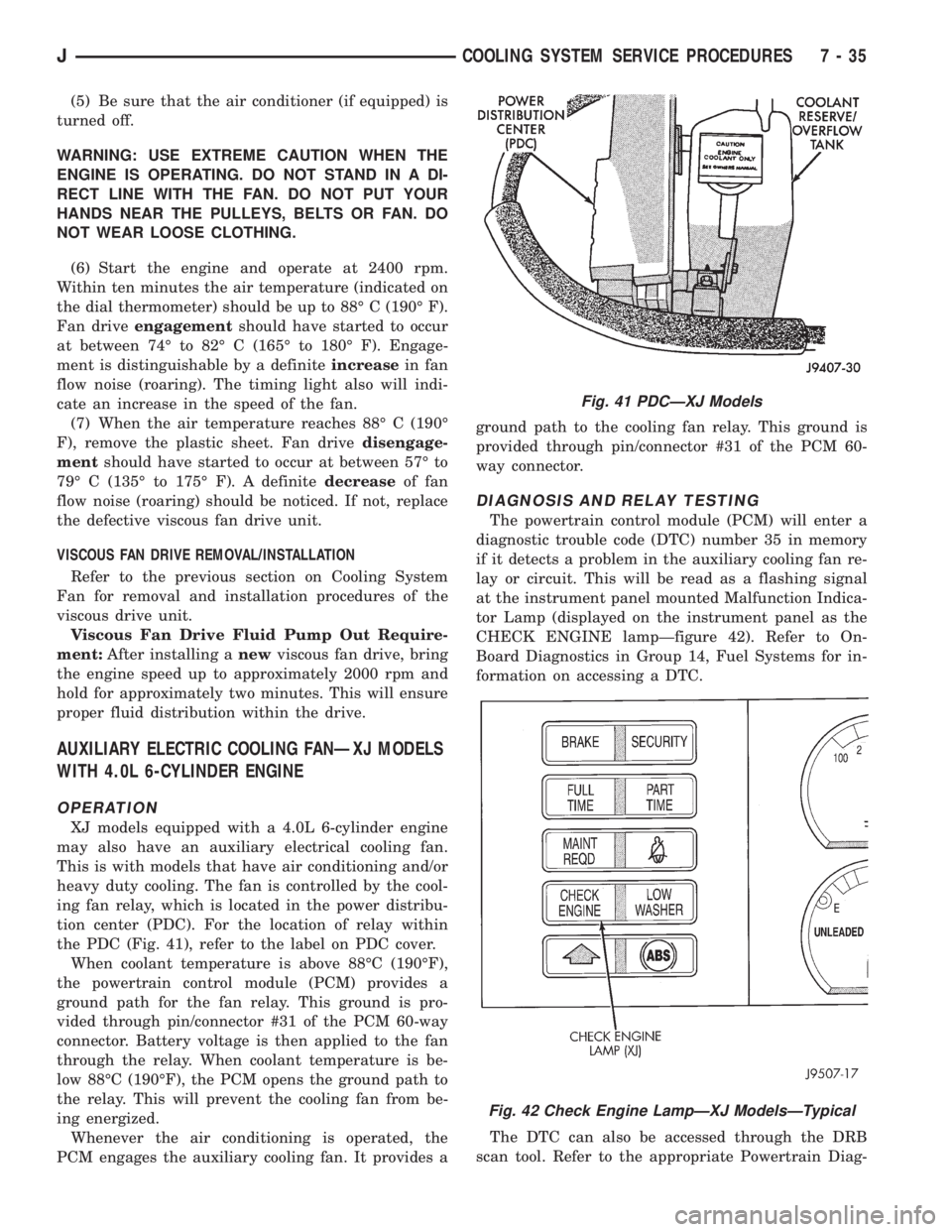
the PDC (Fig. 41), refer to the label on PDC cover.
When coolant temperature is above 88ÉC (190ÉF),
the powertrain control module (PCM) provides a
ground path for the fan relay. This ground is pro-
vided through pin/connector #31 of the PCM 60-way
connector. Battery voltage is then applied to the fan
through the relay. When coolant temperature is be-
low 88ÉC (190ÉF), the PCM opens the ground path to
the relay. This will prevent the cooling fan from be-
ing energized.
Whenever the air conditioning is operated, the
PCM engages the auxiliary cooling fan. It provides aground path to the cooling fan relay. This ground is
provided through pin/connector #31 of the PCM 60-
way connector.
DIAGNOSIS AND RELAY TESTING
The powertrain control module (PCM) will enter a
diagnostic trouble code (DTC) number 35 in memory
if it detects a problem in the auxiliary cooling fan re-
lay or circuit. This will be read as a flashing signal
at the instrument panel mounted Malfunction Indica-
tor Lamp (displayed on the instrument panel as the
CHECK ENGINE lampÐfigure 42). Refer to On-
Board Diagnostics in Group 14, Fuel Systems for in-
formation on accessing a DTC.
The DTC can also be accessed through the DRB
scan tool. Refer to the appropriate Powertrain Diag-
Fig. 41 PDCÐXJ Models
Fig. 42 Check Engine LampÐXJ ModelsÐTypical
JCOOLING SYSTEM SERVICE PROCEDURES 7 - 35
Page 293 of 2198
USING ON-BOARD DIAGNOSTIC SYSTEM
GENERAL INFORMATION
The Powertrain Control Module (PCM) monitors
critical input and output circuits of the charging sys-
tem, making sure they are operational. A Diagnostic
Trouble Code (DTC) is assigned to each input and
output circuit monitored by the OBD system. Some
circuits are checked continuously and some are
checked only under certain conditions.
If the OBD system senses that a monitored circuit
is bad, it will put a DTC into electronic memory. The
DTC will stay in electronic memory as long as the
circuit continues to be bad. The PCM is programmed
to clear the memory after 50 engine starts, if the
problem does not occur again.
DIAGNOSTIC TROUBLE CODES
Diagnostic Trouble Codes (DTC) are two-digit num-
bers flashed on the malfunction indicator (Check En-
gine) lamp that identify which circuit is bad. A DTC
description can also be read using the DRB scan tool.
Refer to Group 14 - Fuel Systems for more informa-
tion.
A DTC does not identify which component in a cir-
cuit is bad. Thus, a DTC should be treated as a
symptom, not as the cause for the problem. In some
cases, because of the design of the diagnostic test
procedure, a DTC can be the reason for another DTCto be set. Therefore, it is important that the test pro-
cedures be followed in sequence, to understand what
caused a DTC to be set.
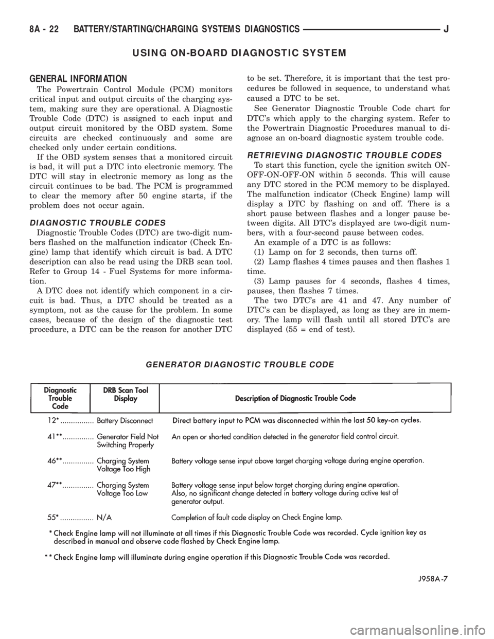
See Generator Diagnostic Trouble Code chart for
DTC's which apply to the charging system. Refer to
the Powertrain Diagnostic Procedures manual to di-
agnose an on-board diagnostic system trouble code.
RETRIEVING DIAGNOSTIC TROUBLE CODES
To start this function, cycle the ignition switch ON-
OFF-ON-OFF-ON within 5 seconds. This will cause
any DTC stored in the PCM memory to be displayed.
The malfunction indicator (Check Engine) lamp will
display a DTC by flashing on and off. There is a
short pause between flashes and a longer pause be-
tween digits. All DTC's displayed are two-digit num-
bers, with a four-second pause between codes.
An example of a DTC is as follows:
(1) Lamp on for 2 seconds, then turns off.
(2) Lamp flashes 4 times pauses and then flashes 1
time.
(3) Lamp pauses for 4 seconds, flashes 4 times,
pauses, then flashes 7 times.
The two DTC's are 41 and 47. Any number of
DTC's can be displayed, as long as they are in mem-
ory. The lamp will flash until all stored DTC's are
displayed (55 = end of test).
GENERATOR DIAGNOSTIC TROUBLE CODE
8A - 22 BATTERY/STARTING/CHARGING SYSTEMS DIAGNOSTICSJ