1995 JEEP CHEROKEE display
[x] Cancel search: displayPage 580 of 2198
Circuit T17 from fuse 3 in the power distribution
center supplies voltage to the coil and contact sides
of the TCC relay. When the PCM provides a ground
path on circuit K54 for the coil side of the relay, the
relay contacts close.
When the relay contacts close, they connect circuit
T17 with circuit T22. Circuit T22 supplies battery
voltage to the case grounded TCC solenoid. Circuit
K54 connects to PCM cavity 54.
HELPFUL INFORMATION
²In the RUN or START position, the ignition switch
connects circuit A1 from fuse 4 in the PDC to circuit
A21.
UPSHIFT LAMP
On vehicles equipped with a manual transmission,
the PCM grounds the up-shift lamp on circuit K54.
Circuit K54 connects to cavity 54 of the PCM.
POWER STEERING PRESSURE SWITCH
The PCM supplies voltage to the power steering
pressure switch on circuit K10. Circuit Z12 provides
ground for the switch. When the switch closes, volt-
age flows through the switch to ground on circuit
Z12. The switch closes during periods of high power
steering pump load and low engine speed; such as
parking maneuvers.
Circuit K10 connects to cavity 10 of the PCM. Cir-
cuit Z12 terminates at the right rear of the engine.
TACHOMETER SIGNAL
The PCM supplies the signal for the tachometer on
circuit G21. Circuit G21 connects to cavity 43 of the
PCM.
MALFUNCTION INDICATOR LAMP (MIL)
The PCM provides ground for the instrument clus-
ter malfunction indicator lamp on circuit G3. The
MIL displays the message CHECK ENGINE when il-
luminated. Circuit F87 provides voltage for the lamp.
DATA LINK CONNECTOR
Circuit F12 supplies battery voltage to the data
link connector. Circuit F12 originates at fuse 11 in
the Power Distribution Center.
Circuit D20 connects to cavity 45 of the PCM. Cir-
cuit D20 is the SCI receive circuit for the PCM.
Circuit D21 connects to cavity 25 of the PCM. Cir-
cuit D21 is the SCI transmit circuit for the PCM.
Circuit Z11 provides ground for the data link con-
nector. Circuit Z11 terminates at the right rear of the
engine. Circuit Z11 also connects to cavity 5 of the
PCM.
HELPFUL INFORMATION
²Circuit Z1 also supplies a ground for the PCM
high current drivers.
²If the system loses ground for the Z11 circuits at
the right rear of the engine, the vehicle will not op-
erate. Check the connection at the ganged-ground cir-
cuit eyelet.
²Circuit F12 splices to supply battery voltage to the
vehicle speed control switch, back-up lamp switch,
A/C compressor clutch relay, windshield washer fluid
level sensor and radiator fan relay (4.0L engines).
BRAKE SWITCH INPUT
Circuit K29 provides the brake switch input to the
PCM. Circuit V40 connects to cavity 29 of the PCM.
POWER (DEVICE) GROUND
Circuit Z12 connects to cavities 11 and 12 of the
PCM. The Z12 circuit provides ground for PCM inter-
nal drivers that operate high current devices like the
injectors and ignition coil.
Internal to the PCM, the power (device) ground cir-
cuit connects to the PCM sensor return circuit (from
circuit K4).
HELPFUL INFORMATION
²The grounding point for circuit Z12 is the right
rear of the engine.
²If the system loses ground for the Z12 circuits at
the rear of the engine, the vehicle will not operate.
Check the connection at the ganged-ground circuit
eyelet.
²On vehicles equipped with the 4.0L engine and au-
tomatic transmission, circuit Z12 splices to provide
ground for the transmission control module.
EXTENDED IDLE SWITCH
On Police Package vehicles, an optional extended
idle switch provides an input to the Powertrain Con-
trol Module (PCM) on circuit K10. Circuit K10 con-
nects to cavity 10 of the PCM. Circuit F60 supplies
battery voltage to the extended idle switch. Circuit
Z1 grounds the switch.
CCD BUS
On vehicles equipped with the 4.0L engine, circuits
D1 and D2 connect the Powertrain Control Module
(PCM) to the CCD Bus. Circuit D1 connects to cavity
26 of the PCM. Circuit D2 connects to cavity 46 of
the PCM. Circuits D1 and D2 are a twisted pair of
wires.
J8W-30 FUEL/IGNITIONÐXJ VEHICLES 8W - 30 - 5
Page 613 of 2198
OIL PRESSURE GAUGE
The case grounded oil pressure sensor is a variable
resistor that connects to circuit G6. Circuit G6 con-
nects to the oil pressure gauge.
Circuit F87 connects to the instrument cluster con-
nector and supplies battery voltage to oil pressure
gauge. The gauge uses two coils. Current passing
through the coils creates a magnetic field. Position of
the gauge needle is controlled by the amount of cur-
rent passing through the coils to ground at the sen-
sor.
OIL PRESSURE WARNING LAMP
The case grounded oil pressure switch connects to
circuit G6. Circuit G6 connects to the oil pressure
warning lamp. Circuit F87 connects to the instru-
ment cluster connector and supplies battery voltage
to oil pressure lamp.
When the oil pressure switch close, battery voltage
flows through the warning lamp to ground through
the switch, illuminating the lamp.
TACHOMETER
The tachometer module in the instrument cluster
operates the tachometer. The Powertrain Control
Module (PCM) supplies the signal for the tachometer
on circuit G21. Circuit G21 connects to cavity 43 of
the PCM.
SPEEDOMETER
The speedometer and odometer receive a signal
from the vehicle speed sensor on circuit G7. Circuit
G7 also connects to the Powertrain Control Module
(PCM) at cavity 47.
ABS WARNING LAMP
Circuit F87 provides power for the ABS warning
lamp at the instrument cluster. Ground for the ABS
warning lamp is provided by either the ABS control
module or by the ABS power relay when the relay is
not energized. The ABS control module illuminates
the lamp by providing ground on circuit B205.
Circuit B205 splices to connect to circuit B235
through a diode. When the ABS power relay is not
energized, it connects circuit B235 to circuit Z12. The
ground path for the warning lamp is through the di-
ode to circuit B235, through the ABS power relay to
ground on circuit Z12.
The diode between circuit B205 and B235 prevents
voltage from flowing to the ABS control module when
the ABS power relay switches to supply power on cir-
cuit B235.
MALFUNCTION INDICATOR LAMP (MIL)
The PCM provides ground for the instrument clus-
ter malfunction indicator lamp on circuit G3. Circuit
G3 connects to cavity 32 of the PCM. Circuit F87provides voltage for the lamp. The MIL displays the
message CHECK ENGINE when illuminated.
For information regarding diagnostic trouble code
access using the MIL lamp, refer to Group 14, Fuel
Systems.
LOW WASHER FLUID WARNING LAMP
Circuit G29 connects the low washer fluid switch to
the warning lamp in the instrument cluster. Circuit
F12 supplies battery voltage to the switch.
When the low washer fluid switch closes, it con-
nects circuits G29 and F12. Battery voltage from cir-
cuit F12 powers the low washer fluid lamp. Circuit
Z1 at the instrument cluster provides ground to illu-
minate the warning lamp.
SEAT BELT INDICATOR WARNING LAMP
The seat belt indicator warning lamp is activated
by the chime/buzzer on circuit G11. Circuit G11 sup-
plies power to instrument cluster for the lamp. Cir-
cuit Z1 provides ground for the lamp at the cluster.
The chime/buzzer module powers circuit G11 after
it receives an input on circuit G10 indicating the seat
belt switch is open.
HIGH-BEAM INDICATOR LAMP
Circuit L3 supplies power for the high-beam indi-
cator lamp. The ground path for the lamp is through
circuit Z1. If the vehicle has Daytime Running
Lamps (DRL), the DRL module powers circuit L3
through circuit G465. On vehicles not equipped with
DRL, the headlamp switch powers circuit L3.
Circuit Z1 provides ground for the indicator lamp
at the cluster.
TURN SIGNAL INDICATOR LAMPS
Circuits L61 and L60 power for the turn signal in-
dicator lamps. Circuit L61 powers the left indicator
lamp. Circuit L60 powers the right indicator lamp.
Circuit Z1 provides ground for the lamps.
BRAKE WARNING LAMP
Circuit F87 supplies power to the park brake lamp.
Ground for the park brake lamp is supplied through
the case grounded park brake switch or brake warn-
ing switch on circuit G9. Circuit G9 Connects to cir-
cuit B203. Circuit B203 connects to the brake
warning lamp at the instrument cluster.
MANUAL TRANSMISSION UP-SHIFT LAMP
Circuit F87 supplies power for the manual trans-
mission up-shift lamp. The lamp illuminates when
the Powertrain Control Module (PCM) provides
ground for the lamp on circuit K54. Circuit K54 con-
nects to cavity 54 of the PCM.
8W - 40 - 2 8W-40 INSTRUMENT CLUSTERÐXJ VEHICLESJ
Page 644 of 2198
AUDIO SYSTEM
RADIO
When the ignition switch is in the ACCESSORY or
RUN position, it connects circuit A1 from fuse 6 in the
Power Distribution Center (PDC) to circuit A48. Cir-
cuit A48 powers circuit F85 through fuse 2 in the fuse
block. Circuit F85 powers the radio.
Circuit Z1 provides ground for the radio. The an-
tenna connects to the rear of the radio.
RADIO MEMORY
Circuit M1 from the Ignition Off Draw (IOD) fuse
(fuse 9) in the fuse block supplies power for the radio
memory. The IOD fuse is removed during vehicle
shipping to prevent excessive battery draw.
Circuit A6 from fuse 16 in the Power Distribution
Center (PDC) supplies voltage to fuse 9. Circuit A7
from fuse 3 in the PDC powers circuit A6 through
fuse 16. Circuits A6, A7 and M1 are HOT at all times.
RADIO ILLUMINATION
Circuit E2 supplies battery voltage to the radio
illumination lamps when the headlamps or parking
lamps are on and the dimmer switch is in the LOW or
ON positions.
Circuit X5 supplies battery voltage for the radio
clock and station frequency display. Circuit X5 origi-
nates at the radio illumination relay and is fed by
either circuit F85 or circuit E2 depending on the
switch position inside the relay.
When the headlamps and parking lamps are off, the
radio illumination relay is in its normal At Rest posi-
tion. In the At Rest position, the relay connects circuit
F85 from fuse 2 in the fuse block to circuit X5.
When the headlamps or parking lamps are on, cir-
cuit L90 from the headlamp switch supplies battery
voltage to the coil side of the radio illumination relay.
Circuit Z1 provides ground for the coil side of the
relay.
When voltage is present on circuit L90, the radio
illumination relay switches from its At Rest position
to connect circuit E2 to circuit X5.
SPEAKERS
There are 3 different radio packages. The standard
radio package includes 2 speakers; one in each front
door. The four speaker system uses speakers in each
front door plus speakers in the rear sound bar. The six
speaker system has the front door speakers, sound bar
speakers and two speakers in the instrument panel.
BASE RADIO
Vehicles with the base radio have a jumper between
the radio and the instrument panel connectors. The
jumper simulates rear speaker load.Circuit X53 feeds the speaker in the left front door.
Circuit X55 is the return from the speaker to the
radio.
Circuit X54 feeds the right front door speaker. Cir-
cuit X56 is the return from the speaker to the radio.
FOUR SPEAKER SYSTEM
Circuit X53 feeds the speaker in the left front door.
Circuit X55 is the return from the speaker to the
radio.
Circuit X54 feeds the right front door speaker. Cir-
cuit X56 is the return from the speaker to the radio.
Circuit X51 feeds the left rear speaker. Circuit X57
is the return from the speaker to the radio.
Circuit X52 feeds the right rear speaker. Circuit
X58 is the return from the speaker to the radio.
SIX SPEAKER SYSTEM
Circuit X53 feeds the left speaker in the instrument
panel. The X53 circuit is double crimped at the in-
strument panel left speaker and branches to the left
front door speaker. Circuit X55 is the return to the
radio from the instrument panel left speaker and left
front door speaker. Circuit X55 is double crimped at
the instrument panel left speaker.
Circuit X54 feeds the right speaker in the instru-
ment panel. The X54 circuit is double crimped at the
instrument panel right speaker and branches to the
right front door speaker. Circuit X56 is the return to
the radio from the instrument panel left speaker and
left front door speaker. Circuit X56 is double crimped
at the instrument panel left speaker.
Circuit X51 feeds the left rear speaker. Circuit X57
is the return from the speaker to the radio.
Circuit X52 feeds the right rear speaker. Circuit
X58 is the return from the speaker to the radio.
DIAGRAM INDEX
Component Page
Fuse Block...........................8W-47-2, 3
Headlamp Switch.........................8W-47-2
Ignition Switch..........................8W-47-2
LCD Relay.............................8W-47-3
Power Distribution Center..................8W-47-2, 3
Radio............................8W-47-2 thru 7
Speakers (Six Speaker System)..............8W-47-4, 5
Speakers (Four Speaker System).............8W-47-6, 7
J8W-47 AUDIO SYSTEMÐXJ VEHICLES 8W -47 - 1
Page 859 of 2198
THROTTLE POSITION SENSOR
From the Powertrain Control Module (PCM), cir-
cuit K6 supplies 5 volts to the throttle position sen-
sor (TPS). Circuit K6 connects to cavity 6 of the
PCM.
Circuit K22 delivers the TPS signal to the PCM.
Circuit K22 connects to cavity 22 of the PCM.
The PCM provides a ground for the throttle posi-
tion sensor signal (circuit K22) through circuit K4.
Circuit K4 connects to cavity 4 of the PCM.
HELPFUL INFORMATION
Refer to Group 14 for throttle position sensor oper-
ation.
Circuit K6 splices to supply 5 volts to the manifold
absolute pressure sensor.
Circuit K22 splices to the transmission control
module.
Circuit K4 splices to supply ground for the signals
from the following:
²Heated oxygen sensor
²Camshaft position sensor
²Crankshaft position sensor
²Intake air temperature sensor
²Manifold absolute pressure sensor
²Engine coolant temperature sensor
²Vehicle speed sensor
MANIFOLD ABSOLUTE PRESSURE SENSOR
From the Powertrain Control Module (PCM), cir-
cuit K6 supplies 5 volts to the manifold absolute
pressure (MAP) sensor. Circuit K6 connects to cavity
6 of the PCM.
Circuit K1 delivers the MAP signal to the PCM.
Circuit K1 connects to cavity 1 of the PCM.
The PCM provides a ground for the MAP sensor
signal (circuit K1) through circuit K4. Circuit K4 con-
nects to cavity 4 of the PCM.
HELPFUL INFORMATION
Refer to Group 14 for MAP sensor operation.
Circuit K6 splices to supply 5 volts to the throttle
position sensor.
Circuit K4 splices to supply ground for the signals
from the following:
²Heated oxygen sensor
²Camshaft position sensor
²Crankshaft position sensor
²Intake air temperature sensor
²Throttle position sensor
²Engine coolant temperature sensor
²Vehicle speed sensor
INTAKE AIR TEMPERATURE SENSOR
The intake air temperature sensor provides an in-
put to the Powertrain Control Module (PCM) on cir-
cuit K21. Circuit K21 connects to cavity 21 of the
PCM.From circuit K21, the intake air temperature sen-
sor draws voltage from the PCM. The sensor is a
variable resistor. As intake air temperature changes,
the resistance in the sensor changes, causing a
change in current draw.
The PCM provides a ground for the intake air tem-
perature sensor signal (circuit K21) through circuit
K4. Circuit K4 connects to cavity 4 of the PCM.
HELPFUL INFORMATION
Circuit K4 splices to supply ground for the signals
from the following:
²Heated oxygen sensor
²Camshaft position sensor
²Crankshaft position sensor
²Throttle position sensor
²Manifold absolute pressure sensor
²Engine coolant temperature sensor
²Vehicle speed sensor
PARK/NEUTRAL POSITION SWITCH
When closed, the case-grounded park/neutral posi-
tion switch provides a ground path on circuit T41 for
the coil side of the starter motor relay. Circuit A41
from the ignition switch provides battery voltage to
the coil side of the relay.
Circuit T41 splices to cavity 30 of the PCM. The
park/neutral position switch provides an input to the
Powertrain Control Module (PCM).
TACHOMETER SIGNAL
The PCM supplies the signal for the tachometer on
circuit G21. Circuit G21 connects to cavity 43 of the
PCM.
MALFUNCTION INDICATOR LAMP (MIL)
The Powertrain Control Module (PCM) provides
ground for the instrument cluster malfunction indica-
tor lamp on circuit G3. The MIL displays the mes-
sage CHECK ENGINE when illuminated. Circuit
F87 provides voltage for the lamp. Circuit G3 con-
nects to cavity 32 of the PCM.
DATA LINK CONNECTOR
Circuit F12 supplies battery voltage to the data
link connector. Circuit F12 originates at fuse 11 in
the Power Distribution Center.
Circuit D20 connects to cavity 45 of the PCM. Cir-
cuit D20 is the SCI receive circuit for the PCM.
Circuit D21 connects to cavity 25 of the PCM. Cir-
cuit D21 is the SCI transmit circuit for the PCM.
Circuit Z11 provides ground for the data link con-
nector. Circuit Z11 also connects to cavity 5 of the
PCM.
8W - 30 - 4 8W-30 FUEL/IGNITIONÐXJ-RHDJ
Page 918 of 2198
RADIO
RADIO
When the ignition switch is in the ACCESSORY or
RUN position, it connects circuit A1 from fuse 6 in
the Power Distribution Center (PDC) to circuit A48.
Circuit A48 powers circuit F85 through fuse 13 in the
fuse block. Circuit F85 powers the radio.
Circuit Z1 provides ground for the radio. The an-
tenna connects to the rear of the radio.
RADIO MEMORY
Circuit M1 from fuse 16 in the Power Distribution
Center (PDC) supplies power for the radio memory.
Circuit A7 from fuse 3 in the PDC supplies voltage
to fuse 16. Circuits A7 and M1 are HOT at all times.
RADIO ILLUMINATION
Circuit E2 supplies battery voltage to the radio il-
lumination lamps when the headlamps or parking
lamps are on and the dimmer switch is in the Low or
On positions.
Circuit X5 supplies battery voltage for the radio
clock and station frequency display. Circuit X5 origi-
nates at the radio illumination relay and is fed by ei-
ther circuit F85 or circuit E2 depending on the
switch position inside the relay.
When the headlamps and parking lamps are off,
the radio illumination relay is in its normal At Rest
position. In the At Rest position, the relay connects
circuit F85 from fuse 13 in the fuse block to circuit
X5.
When the headlamps or parking lamps are on, cir-
cuit L90 from the headlamp switch supplies battery
voltage to the coil side of the radio illumination relay.
Circuit Z1 provides ground for the coil side of the re-
lay.
When voltage is present on circuit L90, the radio
illumination relay switches from its At Rest position
to connect circuit E2 to circuit X5.
HELPFUL INFORMATION
²Circuit A48 supplies voltage to fuse 13 in the fuse
block for circuit F85 when the ignition switch is in
the ACCESSORY or RUN positions. In these posi-
tions, the ignition switch connects circuit A1 from
fuse 6 in the PDC to circuit A48.²Circuit A3 from fuse 5 in the PDC supplies power
to the fuse block for fuse 9. Fuse 9 protects circuit
L7. When the headlamps or parking lamps are ON,
the headlamp switch connects circuit L7 to circuit
L90. When the adjustable dimmer switch is in the
LOW to ON positions, it internally connects circuit
L7 to circuit E2. Circuit E2 powers fuse 25 in the
fuse block. Circuit E2 continues through fuse 25.
POWER ANTENNA
The Power Antenna Relay supplies power to raise
and lower the antenna. Circuit F60 from fuse 7 in
the fuse block powers the relay. Circuit Z1 provides
ground for the relay.
When the radio is turned on, circuit X60 from the
radio energizes the relay to raise the antenna.
SPEAKERS
Circuit X53 feeds the left front speakers. Circuit
X55 is the return from the speakers to the radio.
Circuit X54 feeds the right front speakers. Circuit
X56 is the return from the speakers to the radio.
Circuit X51 feeds the left rear speaker. Circuit X57
is the return from the speaker to the radio.
Circuit X52 feeds the right rear speaker. Circuit
X58 is the return from the speaker to the radio.
DIAGRAM INDEX
Component Page
Fuse 3 (PDC).........................8W-47-2, 4
Fuse 5 (PDC).......................8W-47-2, 4, 5
Fuse 6 (PDC).........................8W-47-2, 4
Fuse 7 (PDC).........................8W-47-2, 4
Fuse 9 (Fuse Block)...................8W-47-2, 4, 5
Fuse 13 (Fuse Block)....................8W-47-2, 4
Fuse 16 (PDC)........................8W-47-2, 4
Fuse 25 (Fuse Block)....................8W-47-2, 4
Headlamp Switch.......................8W-47-2, 4
Ignition Switch..........................8W-47-2
LCD Relay...........................8W-47-3, 5
Power Antenna..........................8W-47-6
Power Antenna Relay......................8W-47-6
Radio...........................8W-47-2 thru 8
Speakers............................8W-47-7, 8
J8W-47 AUDIO SYSTEMÐXJ-RHD 8W - 47 - 1
Page 1119 of 2198
(2) Use Valve Spring Compressor Tool
MD-998772A and compress each valve spring.
(3) Remove the valve locks, retainers, springs and
valve stem oil seals. Discard the oil seals.
(4) Use an Arkansas smooth stone or a jewelers
file to remove any burrs on the top of the valve stem,
especially around the groove for the locks.
(5) Remove the valves, and place them in a rack in
the same order as removed.
VALVE CLEANING
Clean all carbon deposits from the combustion
chambers, valve ports, valve stems, valve stem
guides and head.
Clean all grime and gasket material from the en-
gine cylinder head machined gasket surface.
INSPECTION
Inspect for cracks in the combustion chambers and
valve ports.
Inspect for cracks on the exhaust seat.
Inspect for cracks in the gasket surface at each
coolant passage.
Inspect valves for burned, cracked or warped
heads.
Inspect for scuffed or bent valve stems.
Replace valves displaying any damage.
VALVE REFACING
(1) Use a valve refacing machine to reface the in-
take and exhaust valves to the specified angle.
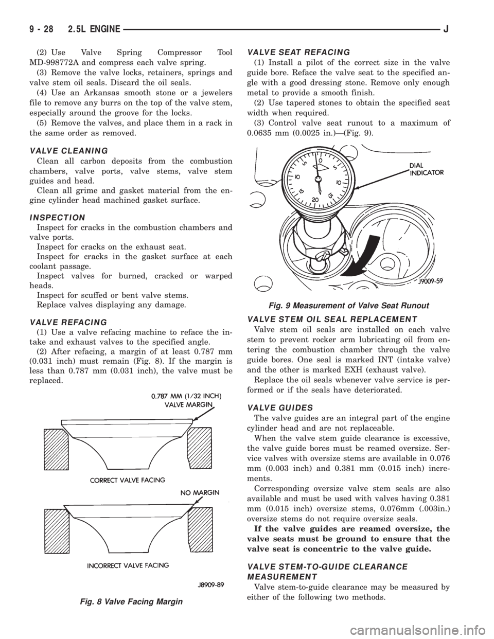
(2) After refacing, a margin of at least 0.787 mm
(0.031 inch) must remain (Fig. 8). If the margin is
less than 0.787 mm (0.031 inch), the valve must be
replaced.
VALVE SEAT REFACING
(1) Install a pilot of the correct size in the valve
guide bore. Reface the valve seat to the specified an-
gle with a good dressing stone. Remove only enough
metal to provide a smooth finish.
(2) Use tapered stones to obtain the specified seat
width when required.
(3) Control valve seat runout to a maximum of
0.0635 mm (0.0025 in.)Ð(Fig. 9).
VALVE STEM OIL SEAL REPLACEMENT
Valve stem oil seals are installed on each valve
stem to prevent rocker arm lubricating oil from en-
tering the combustion chamber through the valve
guide bores. One seal is marked INT (intake valve)
and the other is marked EXH (exhaust valve).
Replace the oil seals whenever valve service is per-
formed or if the seals have deteriorated.
VALVE GUIDES
The valve guides are an integral part of the engine
cylinder head and are not replaceable.
When the valve stem guide clearance is excessive,
the valve guide bores must be reamed oversize. Ser-
vice valves with oversize stems are available in 0.076
mm (0.003 inch) and 0.381 mm (0.015 inch) incre-
ments.
Corresponding oversize valve stem seals are also
available and must be used with valves having 0.381
mm (0.015 inch) oversize stems, 0.076mm (.003in.)
oversize stems do not require oversize seals.
If the valve guides are reamed oversize, the
valve seats must be ground to ensure that the
valve seat is concentric to the valve guide.
VALVE STEM-TO-GUIDE CLEARANCE
MEASUREMENT
Valve stem-to-guide clearance may be measured by
either of the following two methods.
Fig. 8 Valve Facing Margin
Fig. 9 Measurement of Valve Seat Runout
9 - 28 2.5L ENGINEJ
Page 1160 of 2198
counter bolts which were painted in an earlier ser-
vice operation, replace them.
(6) Install the ignition coil and bracket assembly.
(7) Connect the temperature sending unit wire
connector.
(8) Install the spark plugs and tighten to 37 Nzm
(27 ft. lbs.) torque. Connect the ignition wires.
(9) Install the intake and engine exhaust mani-
folds (refer to Group 11, Exhaust System and Intake
Manifold for the proper procedures).
(10) Install the fuel lines and the vacuum advance
hose.
(11) If equipped, attach the power steering pump
and bracket.
(12) Install the push rods, rocker arms, pivots and
bridges in the order they were removed (refer to
Rocker Arms and Push Rods in this section).
(13) Install the engine cylinder head cover.
(14) Attach the air conditioner compressor mount-
ing bracket to the engine cylinder head and block.
Tighten the bolts to 40 Nzm (30 ft. lbs.) torque.
(15) Attach the air conditioning compressor to the
bracket. Tighten the bolts to 27 Nzm (20 ft. lbs.)
torque.
CAUTION: The serpentine drive belt must be routed
correctly. Incorrect routing can cause the water
pump to turn in the opposite direction causing the
engine to overheat.
(16) Install the serpentine drive belt and correctly
tension the belt (refer to Group 7, Cooling System for
the proper procedure).
(17) Install the air cleaner and ducting.
(18) Install the engine cylinder head cover.
(19) Connect the hoses to the engine thermostat
housing and fill the cooling system to the specified
level (refer to Group 7, Cooling Systems for the
proper procedure).
(20) The automatic transmission throttle linkage
and cable must be adjusted after completing the en-
gine cylinder head installation (refer to Group 21,
Transmissions for the proper procedures).(21) Install the temperature sending unit and con-
nect the wire connector.
(22) Connect the fuel line.
(23) Connect negative cable to battery.
(24) Connect the upper radiator hose and heater
hose at the engine thermostat housing.
(25) Fill the cooling system. Check for leaks.
WARNING: USE EXTREME CAUTION WHEN THE
ENGINE IS OPERATING. DO NOT STAND IN DIRECT
LINE WITH THE FAN. DO NOT PUT HANDS NEAR
THE PULLEYS, BELTS OR FAN. DO NOT WEAR
LOOSE CLOTHING.
(26) Operate the engine with the radiator cap off.
Inspect for leaks and continue operating the engine
until the engine thermostat opens. Add coolant, if re-
quired.
VALVES AND VALVE SPRINGS
This procedure is done with the engine cylinder
head removed from the block.
REMOVAL
(1) Remove the engine cylinder head from the cyl-
inder block.
(2) Use Valve Spring Compressor Tool
MD-998772A and compress each valve spring.
(3) Remove the valve locks, retainers, springs and
valve stem oil seals. Discard the oil seals.
(4) Use an Arkansas smooth stone or a jewelers
file to remove any burrs on the top of the valve stem,
especially around the groove for the locks.
(5) Remove the valves, and place them in a rack in
the same order as removed.
VALVE CLEANING
Clean all carbon deposits from the combustion
chambers, valve ports, valve stems, valve stem
guides and head.
Clean all grime and gasket material from the en-
gine cylinder head machined gasket surface.
INSPECTION
Inspect for cracks in the combustion chambers and
valve ports.
Inspect for cracks on the exhaust seat.
Inspect for cracks in the gasket surface at each
coolant passage.
Inspect valves for burned, cracked or warped
heads.
Inspect for scuffed or bent valve stems.
Replace valves displaying any damage.
VALVE REFACING
(1) Use a valve refacing machine to reface the in-
take and exhaust valves to the specified angle.
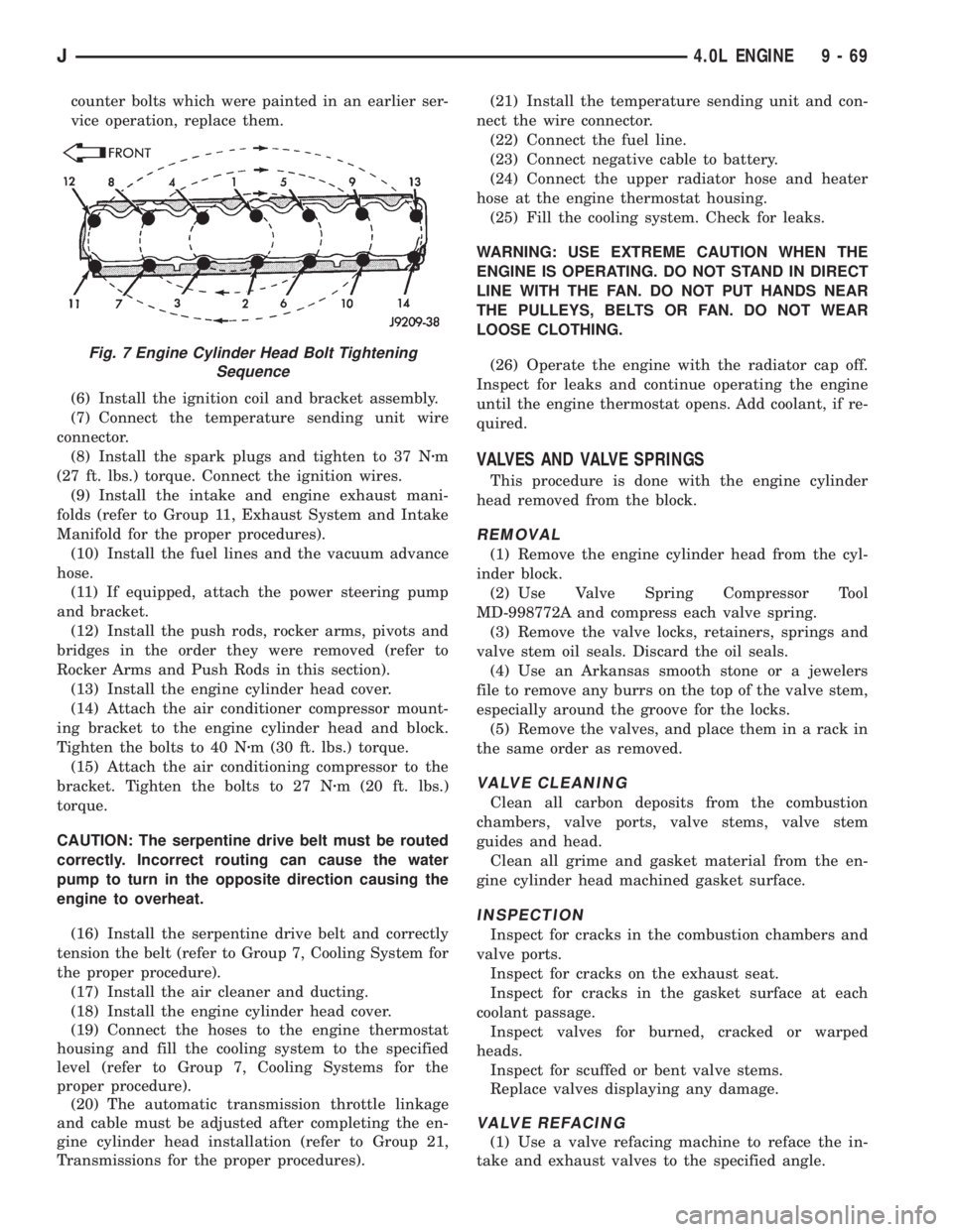
Fig. 7 Engine Cylinder Head Bolt Tightening
Sequence
J4.0L ENGINE 9 - 69
Page 1224 of 2198
codes are not displayed, the problem may be mechan-
ical rather than electronic.
FUEL FILTER
The fuel filter protects the fuel injectors and fuel
pressure regulator from dirt, water and other foreign
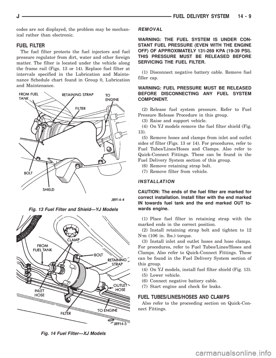
matter. The filter is located under the vehicle along
the frame rail (Figs. 13 or 14). Replace fuel filter at
intervals specified in the Lubrication and Mainte-
nance Schedule chart found in Group 0, Lubrication
and Maintenance.
REMOVAL
WARNING: THE FUEL SYSTEM IS UNDER CON-
STANT FUEL PRESSURE (EVEN WITH THE ENGINE
OFF) OF APPROXIMATELY 131-269 KPA (19-39 PSI).
THIS PRESSURE MUST BE RELEASED BEFORE
SERVICING THE FUEL FILTER.
(1) Disconnect negative battery cable. Remove fuel
filler cap.
WARNING: FUEL PRESSURE MUST BE RELEASED
BEFORE DISCONNECTING ANY FUEL SYSTEM
COMPONENT.
(2) Release fuel system pressure. Refer to Fuel
Pressure Release Procedure in this group.
(3) Raise and support vehicle.
(4) On YJ models remove the fuel filter shield (Fig.
13).
(5) Remove hoses and clamps from inlet and outlet
sides of filter (Figs. 13 or 14). For procedures, refer to
Fuel Tubes/Lines/Hoses and Clamps. Also refer to
Quick-Connect Fittings. These can be found in the
Fuel Delivery System section of this group.
(6) Remove retaining strap bolt.
(7) Remove filter from vehicle.
INSTALLATION
CAUTION: The ends of the fuel filter are marked for
correct installation. Install filter with the end marked
IN towards fuel tank and the end marked OUT to-
wards engine.
(1) Place fuel filter in retaining strap with the
marked ends in the correct position.
(2) Install retaining strap bolt and tighten to 12
Nzm (106 in. lbs.) torque.
(3) Install inlet and outlet hoses and hose clamps.
For procedures, refer to Fuel Tubes/Lines/Hoses and
Clamps. Also refer to Quick-Connect Fittings. These
can be found in the Fuel Delivery System section of
this group.
(4) On YJ models, install fuel filter shield (Fig. 13).
(5) Lower vehicle.
(6) Connect negative battery cable.
(7) Start engine and check for leaks.
FUEL TUBES/LINES/HOSES AND CLAMPS
Also refer to the proceeding section on Quick-Con-
nect Fittings.
Fig. 13 Fuel Filter and ShieldÐYJ Models
Fig. 14 Fuel FilterÐXJ Models
JFUEL DELIVERY SYSTEM 14 - 9