Page 2084 of 2198

RADIO
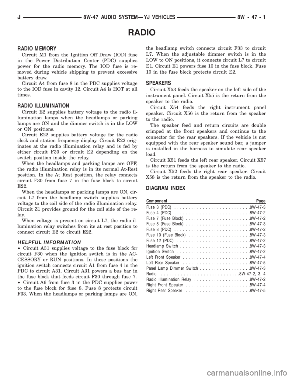
RADIO MEMORY
Circuit M1 from the Ignition Off Draw (IOD) fuse
in the Power Distribution Center (PDC) supplies
power for the radio memory. The IOD fuse is re-
moved during vehicle shipping to prevent excessive
battery draw.
Circuit A4 from fuse 8 in the PDC supplies voltage
to the IOD fuse in cavity 12. Circuit A4 is HOT at all
times.
RADIO ILLUMINATION
Circuit E2 supplies battery voltage to the radio il-
lumination lamps when the headlamps or parking
lamps are ON and the dimmer switch is in the LOW
or ON positions.
Circuit E22 supplies battery voltage for the radio
clock and station frequency display. Circuit E22 orig-
inates at the radio illumination relay and is fed by
either circuit F30 or circuit E2 depending on the
switch position inside the relay.
When the headlamps and parking lamps are OFF,
the radio illumination relay is in its normal At-Rest
position. In the At Rest position, the relay connects
circuit F30 from fuse 7 in the fuse block to circuit
E22.
When the headlamps or parking lamps are ON, cir-
cuit L7 from the headlamp switch supplies battery
voltage to the coil side of the radio illumination relay.
Circuit Z1 provides ground for the coil side of the re-
lay.
When voltage is present on circuit L7, the radio il-
lumination relay switches from its at rest position to
connect circuit E2 to circuit E22.
HELPFUL INFORMATION
²Circuit A31 supplies voltage to the fuse block for
circuit F30 when the ignition switch is in the AC-
CESSORY or RUN positions. In these positions the
ignition switch connects circuit A1 from fuse 4 in the
PDC to circuit A31. Circuit A31 powers a bus bar in
the fuse block that feeds circuit F30 through fuse 7.
²Circuit A6 from fuse 3 in the PDC supplies power
to the fuse block for fuse 8. Fuse 8 protects circuit
F33. When the headlamps or parking lamps are ON,the headlamp switch connects circuit F33 to circuit
L7. When the adjustable dimmer switch is in the
LOW to ON positions, it connects circuit L7 to circuit
E1. Circuit E1 powers fuse 10 in the fuse block. Fuse
10 in the fuse block protects circuit E2.
SPEAKERS
Circuit X53 feeds the speaker on the left side of the
instrument panel. Circuit X55 is the return from the
speaker to the radio.
Circuit X54 feeds the right instrument panel
speaker. Circuit X56 is the return from the speaker
to the radio.
The speaker feed and return circuits are double
crimped at the front speakers and continue to the
connector for the rear speakers. If the vehicle is not
equipped with the rear speaker sound bar, a jumper
is installed in the harness to simulate rear speaker
load.
Circuit X51 feeds the left rear speaker. Circuit X57
is the return from the speaker to the radio.
Circuit X52 feeds the right rear speaker. Circuit
X58 is the return from the speaker to the radio.
DIAGRAM INDEX
Component Page
Fuse 3 (PDC)...........................8W-47-3
Fuse 4 (PDC)...........................8W-47-2
Fuse 7 (Fuse Block).......................8W-47-2
Fuse 8 (Fuse Block).......................8W-47-3
Fuse 8 (PDC)...........................8W-47-2
Fuse 10 (Fuse Block)......................8W-47-3
Fuse 12 (PDC)..........................8W-47-2
Headlamp Switch.........................8W-47-3
Ignition Switch..........................8W-47-2
Left Front Speaker........................8W-47-4
Left Rear Speaker........................8W-47-5
Panel Lamp Dimmer Switch..................8W-47-3
Radio............................8W-47-2, 3, 4
Radio Illumination Relay....................8W-47-2
Right Front Speaker.......................8W-47-4
Right Rear Speaker.......................8W-47-5
J8W-47 AUDIO SYSTEMÐYJ VEHICLES 8W - 47 - 1
Page 2192 of 2198
4
3.0 Using The CD-ROM
3.1 Welcome Page Of A Manual
The Welcome Page is the first page that is displayed to a user after
launching the Acrobat Reader application. Refer to Sections 1.0, and 2.0 of this
CD-ROM Instruction Booklet. Double click on the logo to enter
the Electronic Manual. Figure 3.1-1 is a Welcome Page.
Figure 3.1-1
Page 2193 of 2198
Page 5
03/30/99
Rev. 0
3.2 Tab Page Of A Manual
The tab page contains a listing of all the groups within a manual. Point the cursor
the desired group and click to display the content for a group.
Figure 4.2-1 is a sample tab page for a manual.
Figure 3.2-1
Page 2195 of 2198
Page 7
03/30/99
Rev. 0
3.4 Viewing The Contents Of A Group Within A Manual
Point the cursor over a desired content section and click to
display the contents within a group. Figure 3.4-1 shows the
electronic outline within the left hand window and the document
with associated sections within the right hand window.
Figure 3.4-1
Page 2196 of 2198
8
3.5 Using Electronic Bookmarks For Navigation Within A Manual.
Point the cursor over an item in the electronic outline window which is
located in the left window of the Acrobat Reader.
Click on an outline item to display the contents within a group.
Figure 3.5-1 is a sample document with electronic bookmarks in the
left hand window and the document in the right hand window.
Figure 3.5-1
Page 2197 of 2198

Page 9
03/30/99
Rev. 0
4.0 Using The Acrobat Reader
4.1 Acrobat Reader On-Line Help
The complete user help file can be accessed by selecting the
Help Menu option and then Reader Online Guide option within
the Acrobat Reader application.
4.2 Summary Of Acrobat Reader Toolbar Features
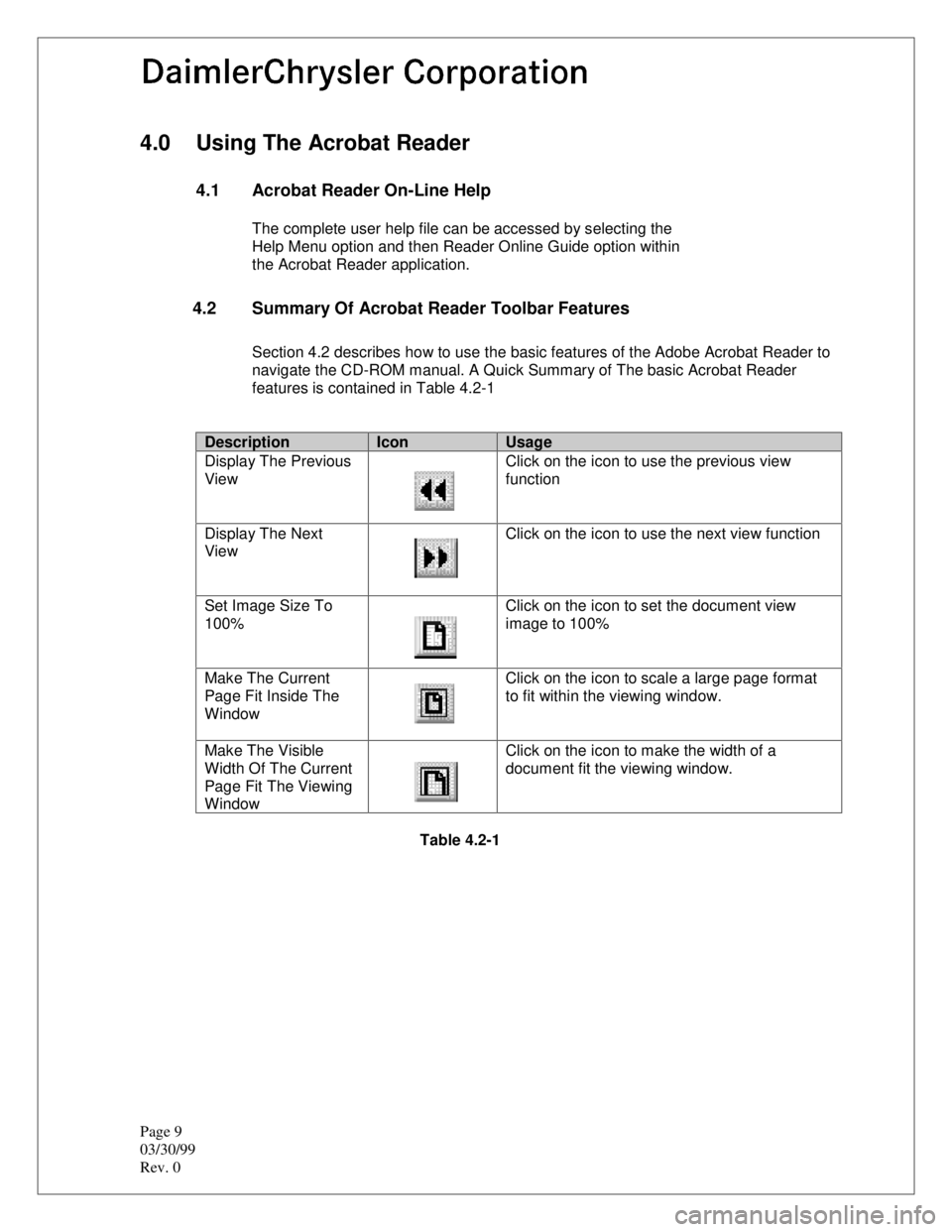
Section 4.2 describes how to use the basic features of the Adobe Acrobat Reader to
navigate the CD-ROM manual. A Quick Summary of The basic Acrobat Reader
features is contained in Table 4.2-1
DescriptionIconUsage
Display The Previous
ViewClick on the icon to use the previous view
function
Display The Next
ViewClick on the icon to use the next view function
Set Image Size To
100%Click on the icon to set the document view
image to 100%
Make The Current
Page Fit Inside The
WindowClick on the icon to scale a large page format
to fit within the viewing window.
Make The Visible
Width Of The Current
Page Fit The Viewing
WindowClick on the icon to make the width of a
document fit the viewing window.
Table 4.2-1
Page 2198 of 2198
10
DescriptionIconUsage
Display The Previous
ViewClick on the icon to use the previous view
function
Display The Next
ViewClick on the icon to use the next view function
Set Image Size To
100%Click on the icon to set the document view
image to 100%
Make The Current
Page Fit Inside The
WindowClick on the icon to scale a large page format
to fit within the viewing window.
Make The Visible
Width Of The Current
Page Fit The Viewing
WindowClick on the icon to make the width of a
document fit the viewing window.
Table 4.2-1