1995 JEEP CHEROKEE horn
[x] Cancel search: hornPage 1082 of 2198
SPLICE LOCATIONS
GENERAL INFORMATION
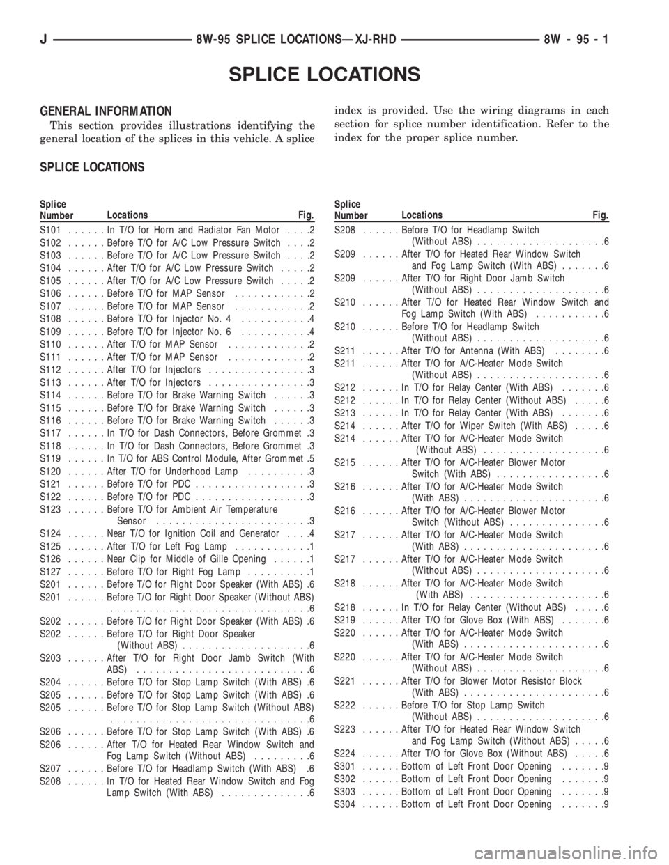
This section provides illustrations identifying the
general location of the splices in this vehicle. A spliceindex is provided. Use the wiring diagrams in each
section for splice number identification. Refer to the
index for the proper splice number.
SPLICE LOCATIONS
Splice
NumberLocations Fig.
S101......InT/OforHorn and Radiator Fan Motor....2
S102......Before T/O for A/C Low Pressure Switch....2
S103......Before T/O for A/C Low Pressure Switch....2
S104......After T/O for A/C Low Pressure Switch.....2
S105......After T/O for A/C Low Pressure Switch.....2
S106......Before T/O for MAP Sensor............2
S107......Before T/O for MAP Sensor............2
S108......Before T/O for Injector No. 4...........4
S109......Before T/O for Injector No. 6...........4
S110......After T/O for MAP Sensor.............2
S111......After T/O for MAP Sensor.............2
S112......After T/O for Injectors................3
S113......After T/O for Injectors................3
S114......Before T/O for Brake Warning Switch......3
S115......Before T/O for Brake Warning Switch......3
S116......Before T/O for Brake Warning Switch......3
S117......InT/OforDash Connectors, Before Grommet .3
S118......InT/OforDash Connectors, Before Grommet .3
S119......InT/OforABSControl Module, After Grommet .5
S120......After T/O for Underhood Lamp..........3
S121......Before T/O for PDC..................3
S122......Before T/O for PDC..................3
S123......Before T/O for Ambient Air Temperature
Sensor........................3
S124......Near T/O for Ignition Coil and Generator....4
S125......After T/O for Left Fog Lamp............1
S126......Near Clip for Middle of Gille Opening......1
S127......Before T/O for Right Fog Lamp..........1
S201......Before T/O for Right Door Speaker (With ABS) .6
S201......Before T/O for Right Door Speaker (Without ABS)
...............................6
S202......Before T/O for Right Door Speaker (With ABS) .6
S202......Before T/O for Right Door Speaker
(Without ABS)....................6
S203......After T/O for Right Door Jamb Switch (With
ABS)...........................6
S204......Before T/O for Stop Lamp Switch (With ABS) .6
S205......Before T/O for Stop Lamp Switch (With ABS) .6
S205......Before T/O for Stop Lamp Switch (Without ABS)
...............................6
S206......Before T/O for Stop Lamp Switch (With ABS) .6
S206......After T/O for Heated Rear Window Switch and
Fog Lamp Switch (Without ABS).........6
S207......Before T/O for Headlamp Switch (With ABS) .6
S208......InT/OforHeated Rear Window Switch and Fog
Lamp Switch (With ABS)..............6Splice
NumberLocations Fig.
S208......Before T/O for Headlamp Switch
(Without ABS)....................6
S209......After T/O for Heated Rear Window Switch
and Fog Lamp Switch (With ABS).......6
S209......After T/O for Right Door Jamb Switch
(Without ABS)....................6
S210......After T/O for Heated Rear Window Switch and
Fog Lamp Switch (With ABS)...........6
S210......Before T/O for Headlamp Switch
(Without ABS)....................6
S211......After T/O for Antenna (With ABS)........6
S211......After T/O for A/C-Heater Mode Switch
(Without ABS)....................6
S212......InT/OforRelay Center (With ABS).......6
S212......InT/OforRelay Center (Without ABS).....6
S213......InT/OforRelay Center (With ABS).......6
S214......After T/O for Wiper Switch (With ABS).....6
S214......After T/O for A/C-Heater Mode Switch
(Without ABS)...................6
S215......After T/O for A/C-Heater Blower Motor
Switch (With ABS).................6
S216......After T/O for A/C-Heater Mode Switch
(With ABS)......................6
S216......After T/O for A/C-Heater Blower Motor
Switch (Without ABS)...............6
S217......After T/O for A/C-Heater Mode Switch
(With ABS)......................6
S217......After T/O for A/C-Heater Mode Switch
(Without ABS)....................6
S218......After T/O for A/C-Heater Mode Switch
(With ABS).....................6
S218......InT/OforRelay Center (Without ABS).....6
S219......After T/O for Glove Box (With ABS).......6
S220......After T/O for A/C-Heater Mode Switch
(With ABS)......................6
S220......After T/O for A/C-Heater Mode Switch
(Without ABS)....................6
S221......After T/O for Blower Motor Resistor Block
(With ABS)......................6
S222......Before T/O for Stop Lamp Switch
(Without ABS)....................6
S223......After T/O for Heated Rear Window Switch
and Fog Lamp Switch (Without ABS).....6
S224......After T/O for Glove Box (Without ABS).....6
S301......Bottom of Left Front Door Opening.......9
S302......Bottom of Left Front Door Opening.......9
S303......Bottom of Left Front Door Opening.......9
S304......Bottom of Left Front Door Opening.......9
J8W-95 SPLICE LOCATIONSÐXJ-RHD 8W - 95 - 1
Page 1338 of 2198
(2) Wrap a single layer of plastic tape around the
pitman shaft threads and splines. This will protect
the replacement seals during installation.
(3) Install the seal with a suitable size socket.
(4) Remove the tape from the shaft.
(5) Center the steering gear.
(6) Align and install the pitman arm.
(7) Install the washer and retaining nut on the pit-
man shaft. Tighten the nut to 251 Nzm (185 ft. lbs.)
torque.
GEAR ADJUSTMENTS IN VEHICLE
REMOVE
(1) Raise and support the vehicle.
(2) Mark the pitman shaft and pitman arm for in-
stallation reference. Remove the pitman arm from
the shaft.
(3) Loosen the adjuster lock nut then back the ad-
juster plug off 1/4 turn.
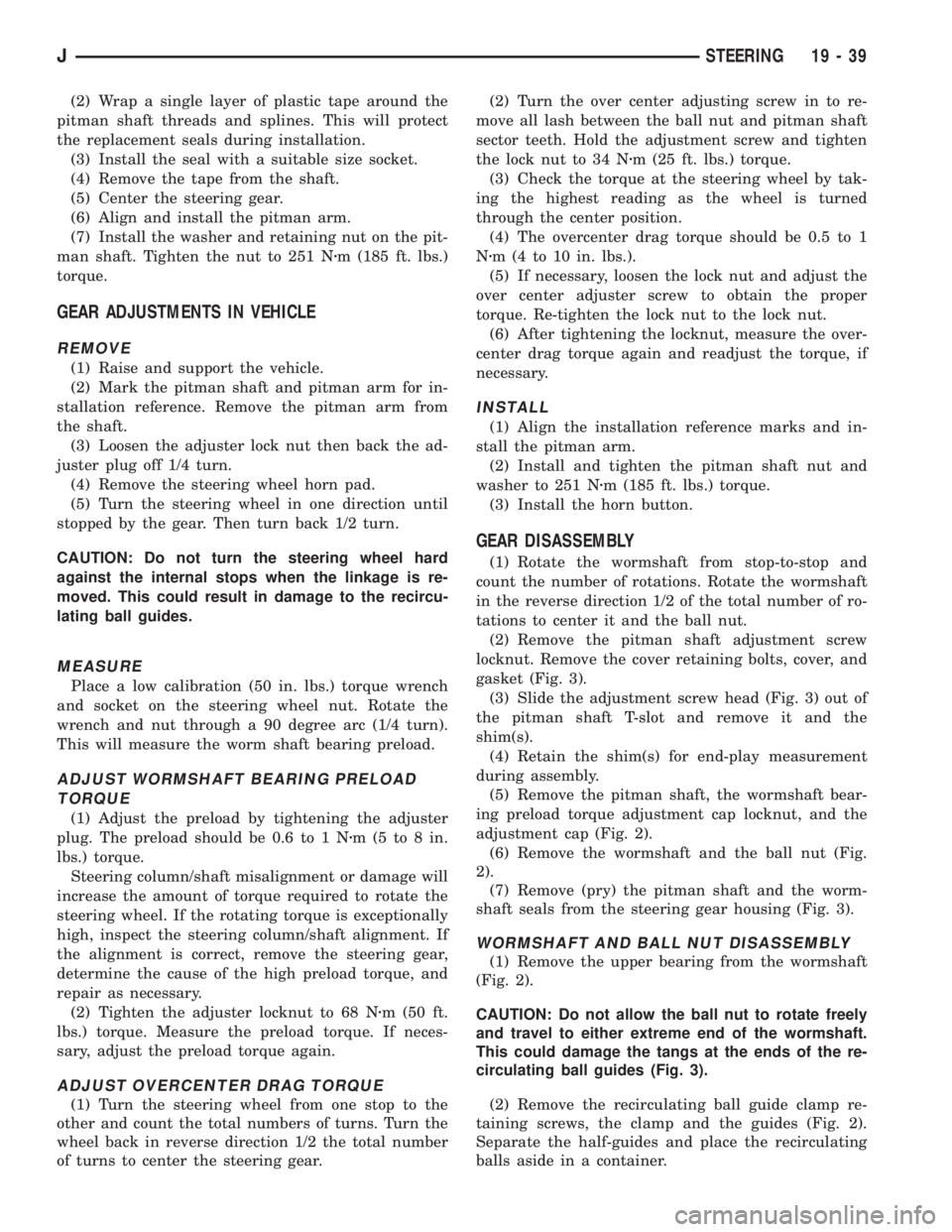
(4) Remove the steering wheel horn pad.
(5) Turn the steering wheel in one direction until
stopped by the gear. Then turn back 1/2 turn.
CAUTION: Do not turn the steering wheel hard
against the internal stops when the linkage is re-
moved. This could result in damage to the recircu-
lating ball guides.
MEASURE
Place a low calibration (50 in. lbs.) torque wrench
and socket on the steering wheel nut. Rotate the
wrench and nut through a 90 degree arc (1/4 turn).
This will measure the worm shaft bearing preload.
ADJUST WORMSHAFT BEARING PRELOAD
TORQUE
(1) Adjust the preload by tightening the adjuster
plug. The preload should be 0.6 to 1 Nzm(5to8in.
lbs.) torque.
Steering column/shaft misalignment or damage will
increase the amount of torque required to rotate the
steering wheel. If the rotating torque is exceptionally
high, inspect the steering column/shaft alignment. If
the alignment is correct, remove the steering gear,
determine the cause of the high preload torque, and
repair as necessary.
(2) Tighten the adjuster locknut to 68 Nzm (50 ft.
lbs.) torque. Measure the preload torque. If neces-
sary, adjust the preload torque again.
ADJUST OVERCENTER DRAG TORQUE
(1) Turn the steering wheel from one stop to the
other and count the total numbers of turns. Turn the
wheel back in reverse direction 1/2 the total number
of turns to center the steering gear.(2) Turn the over center adjusting screw in to re-
move all lash between the ball nut and pitman shaft
sector teeth. Hold the adjustment screw and tighten
the lock nut to 34 Nzm (25 ft. lbs.) torque.
(3) Check the torque at the steering wheel by tak-
ing the highest reading as the wheel is turned
through the center position.
(4) The overcenter drag torque should be 0.5 to 1
Nzm (4 to 10 in. lbs.).
(5) If necessary, loosen the lock nut and adjust the
over center adjuster screw to obtain the proper
torque. Re-tighten the lock nut to the lock nut.
(6) After tightening the locknut, measure the over-
center drag torque again and readjust the torque, if
necessary.
INSTALL
(1) Align the installation reference marks and in-
stall the pitman arm.
(2) Install and tighten the pitman shaft nut and
washer to 251 Nzm (185 ft. lbs.) torque.
(3) Install the horn button.
GEAR DISASSEMBLY
(1) Rotate the wormshaft from stop-to-stop and
count the number of rotations. Rotate the wormshaft
in the reverse direction 1/2 of the total number of ro-
tations to center it and the ball nut.
(2) Remove the pitman shaft adjustment screw
locknut. Remove the cover retaining bolts, cover, and
gasket (Fig. 3).
(3) Slide the adjustment screw head (Fig. 3) out of
the pitman shaft T-slot and remove it and the
shim(s).
(4) Retain the shim(s) for end-play measurement
during assembly.
(5) Remove the pitman shaft, the wormshaft bear-
ing preload torque adjustment cap locknut, and the
adjustment cap (Fig. 2).
(6) Remove the wormshaft and the ball nut (Fig.
2).
(7) Remove (pry) the pitman shaft and the worm-
shaft seals from the steering gear housing (Fig. 3).
WORMSHAFT AND BALL NUT DISASSEMBLY
(1) Remove the upper bearing from the wormshaft
(Fig. 2).
CAUTION: Do not allow the ball nut to rotate freely
and travel to either extreme end of the wormshaft.
This could damage the tangs at the ends of the re-
circulating ball guides (Fig. 3).
(2) Remove the recirculating ball guide clamp re-
taining screws, the clamp and the guides (Fig. 2).
Separate the half-guides and place the recirculating
balls aside in a container.
JSTEERING 19 - 39
Page 1349 of 2198
(2) Disconnect the battery negative (ground) cable
and isolate.
(3) Disarm the airbag (refer to group 8M, Electri-
cal for proper and safe procedures).
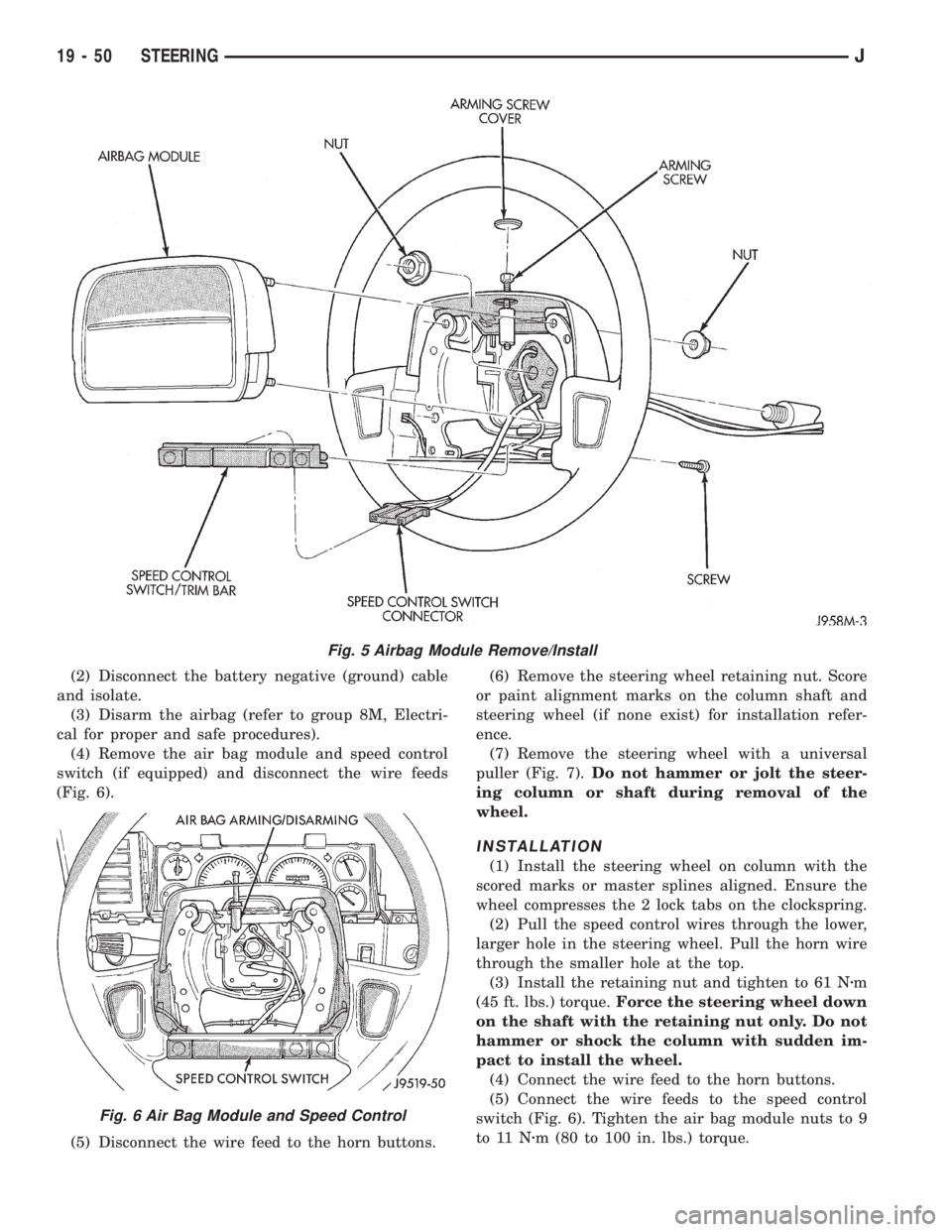
(4) Remove the air bag module and speed control
switch (if equipped) and disconnect the wire feeds
(Fig. 6).
(5) Disconnect the wire feed to the horn buttons.(6) Remove the steering wheel retaining nut. Score
or paint alignment marks on the column shaft and
steering wheel (if none exist) for installation refer-
ence.
(7) Remove the steering wheel with a universal
puller (Fig. 7).Do not hammer or jolt the steer-
ing column or shaft during removal of the
wheel.
INSTALLATION
(1) Install the steering wheel on column with the
scored marks or master splines aligned. Ensure the
wheel compresses the 2 lock tabs on the clockspring.
(2) Pull the speed control wires through the lower,
larger hole in the steering wheel. Pull the horn wire
through the smaller hole at the top.
(3) Install the retaining nut and tighten to 61 Nzm
(45 ft. lbs.) torque.Force the steering wheel down
on the shaft with the retaining nut only. Do not
hammer or shock the column with sudden im-
pact to install the wheel.
(4) Connect the wire feed to the horn buttons.
(5) Connect the wire feeds to the speed control
switch (Fig. 6). Tighten the air bag module nuts to 9
to 11 Nzm (80 to 100 in. lbs.) torque.
Fig. 5 Airbag Module Remove/Install
Fig. 6 Air Bag Module and Speed Control
19 - 50 STEERINGJ
Page 1351 of 2198
(4) From the end of travel, rotate the rotor 2 1/2
full turns in the COUNTER CLOCKWISE direction.
The horn wire should end up at the top and the
squib wire at the bottom (Fig. 9).
(5) Install the steering wheel and air bag module,
refer to Steering Wheel Installation.
COLUMN ASSEMBLY REPLACEMENT
CAUTION: Bumping, jolting and hammering on the
steering column shaft and gear shift tube must be
avoided during all service procedures.
REMOVAL
(1) Make sure the front wheels are in thestraight
aheadposition.
(2) Observe Cautions and disconnect the negative
(ground) cable from the battery.
(3) Disarm airbag, refer to Arming/Disarming Air-
bag in this section.
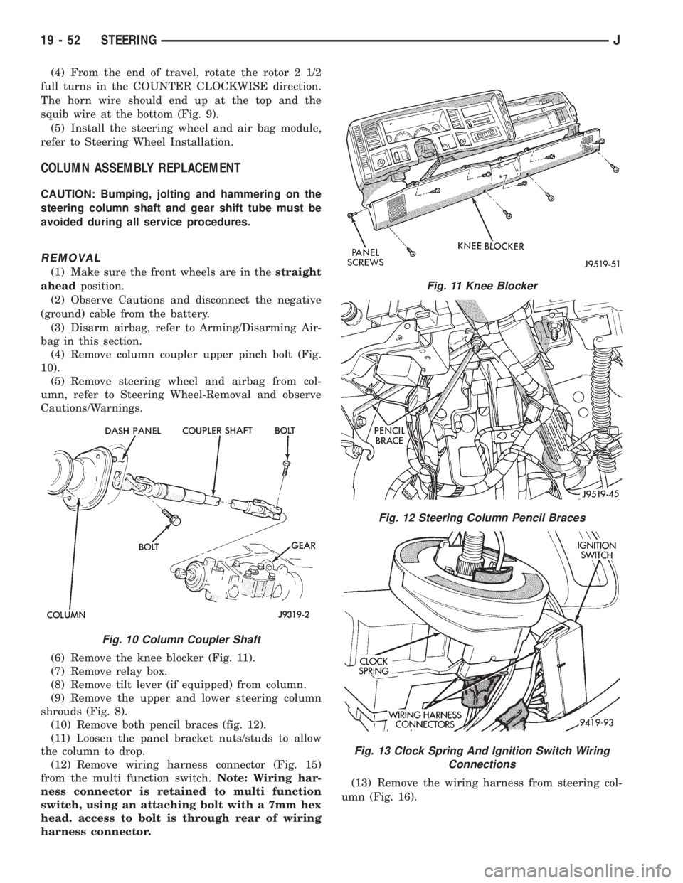
(4) Remove column coupler upper pinch bolt (Fig.
10).
(5) Remove steering wheel and airbag from col-
umn, refer to Steering Wheel-Removal and observe
Cautions/Warnings.
(6) Remove the knee blocker (Fig. 11).
(7) Remove relay box.
(8) Remove tilt lever (if equipped) from column.
(9) Remove the upper and lower steering column
shrouds (Fig. 8).
(10) Remove both pencil braces (fig. 12).
(11) Loosen the panel bracket nuts/studs to allow
the column to drop.
(12) Remove wiring harness connector (Fig. 15)
from the multi function switch.Note: Wiring har-
ness connector is retained to multi function
switch, using an attaching bolt with a 7mm hex
head. access to bolt is through rear of wiring
harness connector.(13) Remove the wiring harness from steering col-
umn (Fig. 16).
Fig. 10 Column Coupler Shaft
Fig. 11 Knee Blocker
Fig. 12 Steering Column Pencil Braces
Fig. 13 Clock Spring And Ignition Switch Wiring
Connections
19 - 52 STEERINGJ
Page 1357 of 2198
STEERING COLUMNÐYJ
INDEX
page page
Assembly............................... 63
Assembly............................... 71
Column Replacement...................... 58
Disassembly............................. 66DisassemblyÐColumn or Console Shift......... 60
Non-Tilt Steering Column................... 60
Steering Wheel........................... 58
Tilt Steering Column....................... 66
The column may be disassembled and reassembled.
Also most steering column components can be serviced
without removing the column from the vehicle. For ad-
ditional information, refer to Group 8H, Electrical.
CAUTION: Bumping, jolting and hammering on the
steering column shaft and gear shift tube must be
avoided during all service procedures.
CAUTION: Disconnect negative (ground) cable from the
battery before servicing any component on the column.
Safety goggles should be worn at all times
when involved with steering column service.
STEERING WHEEL
REMOVAL
(1) Make sure the front wheels are in thestraight
aheadposition.
(2) Disconnect the negative (ground) cable from the
battery.
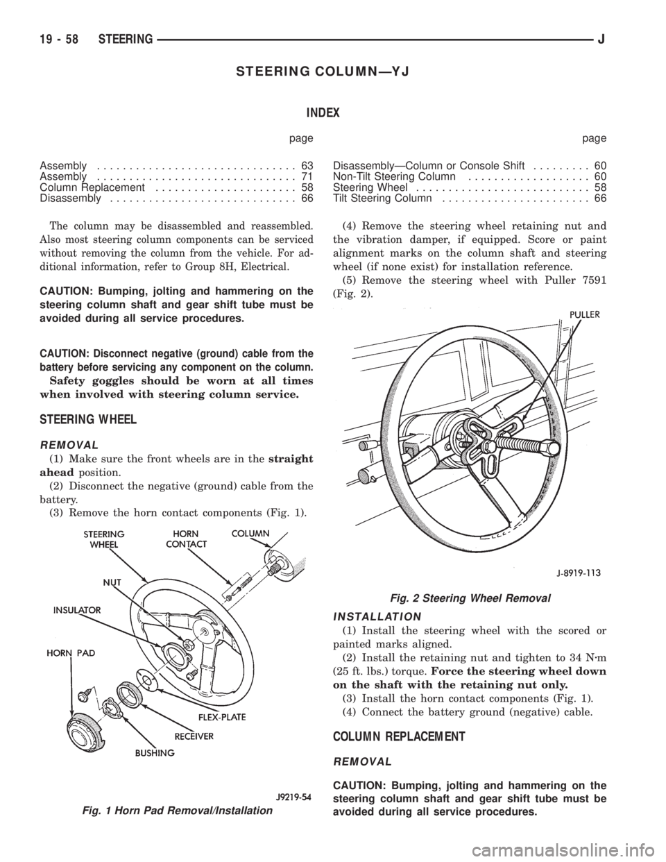
(3) Remove the horn contact components (Fig. 1).(4) Remove the steering wheel retaining nut and
the vibration damper, if equipped. Score or paint
alignment marks on the column shaft and steering
wheel (if none exist) for installation reference.
(5) Remove the steering wheel with Puller 7591
(Fig. 2).
INSTALLATION
(1) Install the steering wheel with the scored or
painted marks aligned.
(2) Install the retaining nut and tighten to 34 Nzm
(25 ft. lbs.) torque.Force the steering wheel down
on the shaft with the retaining nut only.
(3) Install the horn contact components (Fig. 1).
(4) Connect the battery ground (negative) cable.
COLUMN REPLACEMENT
REMOVAL
CAUTION: Bumping, jolting and hammering on the
steering column shaft and gear shift tube must be
avoided during all service procedures.
Fig. 1 Horn Pad Removal/Installation
Fig. 2 Steering Wheel Removal
19 - 58 STEERINGJ
Page 1739 of 2198
RADIATOR SUPPORT CROSSMEMBERÐXJ
REMOVAL
(1) Remove the grille opening panel (GOP).
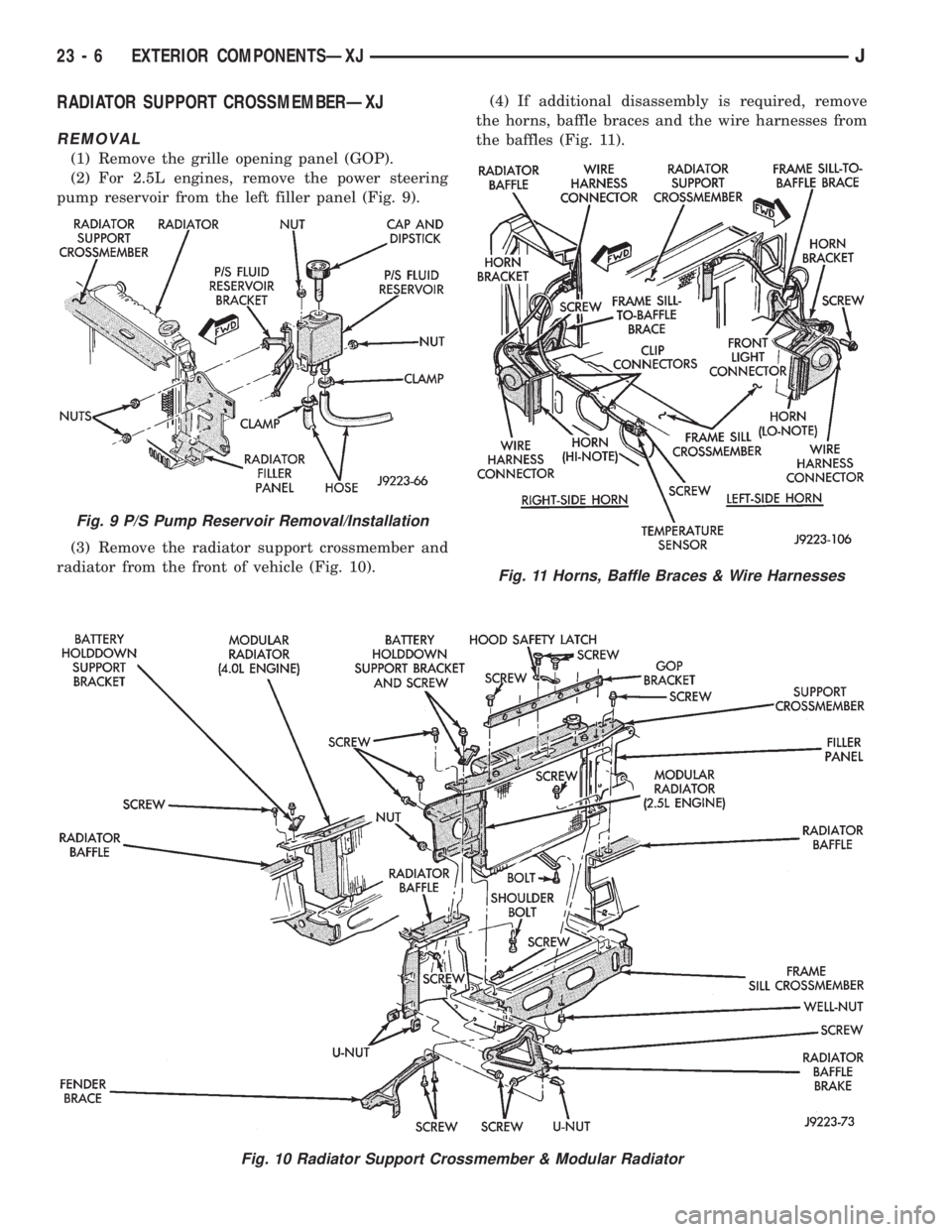
(2) For 2.5L engines, remove the power steering
pump reservoir from the left filler panel (Fig. 9).
(3) Remove the radiator support crossmember and
radiator from the front of vehicle (Fig. 10).(4) If additional disassembly is required, remove
the horns, baffle braces and the wire harnesses from
the baffles (Fig. 11).
Fig. 10 Radiator Support Crossmember & Modular Radiator
Fig. 9 P/S Pump Reservoir Removal/Installation
Fig. 11 Horns, Baffle Braces & Wire Harnesses
23 - 6 EXTERIOR COMPONENTSÐXJJ
Page 1740 of 2198
INSTALLATION
(1) If removed, install the horns, baffle braces and
the wire harnesses on the baffles (Fig. 11).
(2) Position the radiator and the radiator support
crossmember at the front of vehicle (Fig. 10). Install
and tighten screws to 9 Nzm (76 in-lbs) torque.
(3) For 2.5L engines, install the power steering
pump reservoir on the left filler panel (Fig. 9).
(4) Install the grille opening panel (GOP).
HOODÐXJ
The hood service procedures included in this sec-
tion include:
²Hood removal and installation.
²Hood adjustment.
²HingeÐlatchÐstriker service (Fig. 12).
²Latch release cable service.
JEXTERIOR COMPONENTSÐXJ 23 - 7
Page 1845 of 2198
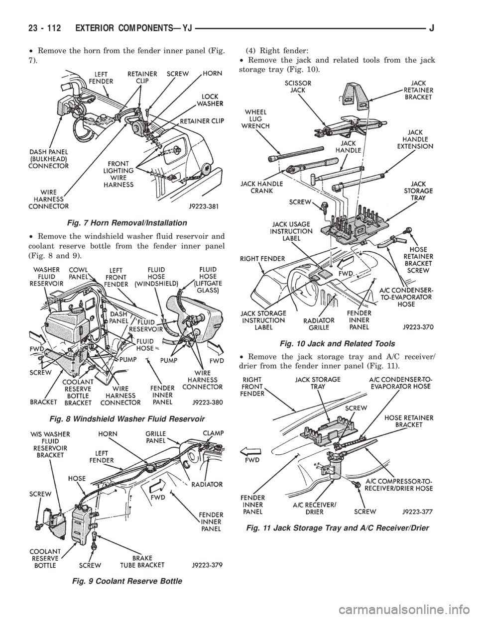
²Remove the horn from the fender inner panel (Fig.
7).
²Remove the windshield washer fluid reservoir and
coolant reserve bottle from the fender inner panel
(Fig. 8 and 9).(4) Right fender:
²Remove the jack and related tools from the jack
storage tray (Fig. 10).
²Remove the jack storage tray and A/C receiver/
drier from the fender inner panel (Fig. 11).
Fig. 7 Horn Removal/Installation
Fig. 8 Windshield Washer Fluid Reservoir
Fig. 9 Coolant Reserve Bottle
Fig. 10 Jack and Related Tools
Fig. 11 Jack Storage Tray and A/C Receiver/Drier
23 - 112 EXTERIOR COMPONENTSÐYJJ