1994 MAZDA MX-5 ECU
[x] Cancel search: ECUPage 10 of 1708

SAE STANDARDS SAE STANDARDS In accordance with new regulations, SAE (Society of Automotive Engineers) standard names and abbreviations are now used in this manual. The table below lists the names and abbreviations that have 4 been used in Mazda manuals up to now and their SAE equivalents. 46UGIX-047 Engine and Emission Systems Accelerator Pedal Air Cleaner Housing I Mixture Control Solenoid I F2 Carburetor ] Abbreviation AP ACH MCS VAF M AF Abbreviation - - - - - Volume Airflow Sensor I I Name Accelerator Pedal Air Cleaner AirlFuel (NF) Solenoid Valve Airflow Meter Airflow Sensor I Mass Airflow Sensor I I Alternator I I - - - -~ I Barometric Absolute Pressure I I Sensor I I Alternator Atmospheric Pressure Sensor I - 1 Carburetor CARB 1 Catalytic Converter OC ALT BAR0 Carburetor 1 Oxidation Catalvst I - - - - - I Direct Ignition I DL1 EG I 1 Electronic Gasoline lniection Svstem I CIS Three Way Catalyst Warm Up Three Way Catalyst Fuel Pump Relay Coolant Fan Control Crankshaft Position Sensor Data Link Connector Circuit Opening Relay Cooling Fan Control Crank Angle Sensor Diaanosis Connector Distributorless Ignition I Continuous Fuel lniection Svstem I 1 #1 #2 FPR C FC CPS DLC I Previous Standard SAE Standard Name I Remark - ( Electronic Spark Ignition EGR Gas Sensor EGR Position Sensor EGR Position Switch El Electronic Ignition 1 #3 EGR Function Control I - I EGR Modulator Solenoid I EGRC 4 ECU I Evaporative Emission Control Svstem I EVAP - - I -,--- I - I Exhaust Gas Recirculation System I EGR Engine Control Unit PCM PCME Engine Modification Ennine Speed EM RPM - - - - - Feedback System Flexible Fuel - I Intercooler Powertrain Control Module I #5 I EGR Function Sensor CLS FF Fuel Pump IC Regulator Intake Air Thermosensor CAC I Powertrain Control Module (Engine) I #4 FP VR IATS - I ISC Solenoid Valve I IACV Engine Modification I Engine Speed - Fuel Evaporative System I Exhaust Gas Recirculation 1 System name 1 Closed Loop System I Flexible Fuel Knock Sensor I I - ( Knock Sensor I KS I Malfunction Indicator Light I I - I Malfunction Indicator Liaht MIL Multiport Fuel Injection Oxidation Catalyst - 1 Multiport Fuel Injection #1: Directy connected to exhaust manifold #2: In some models, there is a "Fuel Pump Relay" that controls pump speed. That relay is now called the 'Fuel Pump Relay (Speed)". #3: Controlled by the PCME (PCM) 4 #4: EGR valve controller device name #5: Device that controls engine and powertrain MFI - 1 Oxidizina Converter OC Gartner Banana
Page 18 of 1708

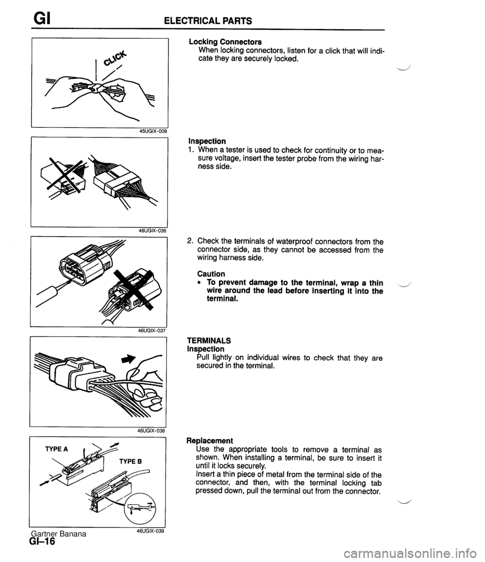
GI ELECTRICAL PARTS Locking Connectors When locking connectors, listen for a click that will indi- cate they are securely locked. 4' Inspection 1. When a tester is used to check for continuity or to mea- sure voltage, insert the tester probe from the wiring har- ness side. I I 46UGIX-039 GI-I 6 2. Check the terminals of waterproof connectors from the connector side, as they cannot be accessed from the wiring harness side. Caution To prevent damage to the terminal, wrap a thin ..J wire around the lead before inserting it into the terminal. TERMINALS lnspection Pull lightly on individual wires to check that they are secured in the terminal. Replacement Use the appropriate tools to remove a terminal as shown. When installing a terminal, be sure to insert it until it locks securely. Insert a thin piece of metal from the terminal side of the connector, and then, with the terminal locking tab pressed down, pull the terminal out from the connector. b' Gartner Banana
Page 111 of 1708

B ASSEMBLY TIMING MARK Timing Belt Pulley 1. lnstall the timing belt pulley. 2. lnstall the pulley woodruff key with the tapered side to- ward the oil pump body. d Idler lnstall the idler. Tightening torque: 38-51 N.m (3.8-5.3 kgf.m, 28-38 ftlbf) Tensioner and Tensioner Spring 1. lnstall the tensioner and the tensioner spring. 2. Temporarily secure the tensioner with the spring fully ex- tended. Timing Belt 1, Turn the crankshaft and align the timing belt pulley mark with the timing mark. Do not turn the crankshaft counter- clockwise. 2. Verify that the camshaft pulley marks are aligned with the seal plate marks. E for intake side and I for exhaust side. Do not turn the crankshaft counterclockwise. 3. lnstall the timing belt so that there is no looseness at the idler side or between the two camshaft pulleys. 4. lnstall the pulley boss and pulley lock bolt. 5. Turn the crankshaft two turns clockwise, and align the timing belt pulley mark with the timing mark. Do not turn the crankshaft counterclockwise. 6. Verify that the camshaft pulley marks are aligned with the seal plate marks. J If not aligned, remove the timing belt and repeat from tensioner installation. Gartner Banana
Page 165 of 1708

TROUBLESHOOTING GUIDE Warning Fuel vapor is hazardous. It can very easily ignite, causing serious injury and damage. Always keep sparks and flames away from fuel. Fuel in the fuel system is under high pressure when the engine is not running. 4 Warning Fuel line spills and leaks are dangerous. Fuel can ignite and cause serious injuries or death and damage. Fuel can also irritate skin and eyes. To prevent this, always complete the following "Fuel Line Safety Procedures". 35UOFX-008 F-73 F-73 F-74 Fuel Line Safety Procedures A. Release the fuel pressure before disconnecting a fuel line. 1. Start the engine. u 2. Disconnect the fuel pump relay connector. 3. After the engine stalls, turn the ignition switch to OFF. 4. Reconnect the fuel pump relay connector. B. Avoid leakage. 1. When disconnecting a fuel line hose, wrap a rag around it to protect against fuel leakage. 2. Plug the hose after removal. C. Install hose clamps to secure the fuel pressure gauge connections. Self-Diagnosis Checker does not indicate Diagnostic Trouble Code No. but MIL comes on Self-Diagnosis Checker indicates Diagnostic Trouble Code No, of input device but MIL never comes ON Blower fan operates but no cool air is discharged 32 33 34 Pinching Hose When pinching an air hose or fuel hose with pliers, wrap the hose with a rag to prevent damage. MIL always ON MIL never ON NC does not work Checking ignition spark When checking ignition spark condition, hold the high- tension lead with insulated pliers. Note If a timing light is used to check for spark, some lights do not light at the number 2 and 4 cylinders even if the ignition system is normal. J Gartner Banana
Page 247 of 1708

INTAKE AIR SYSTEM INTAKE AIR SYSTEM COMPONENTS Removal 1 Inspection l Installation Warning Fuel vapor is hazardous. It can very easily ignite, causing serious injury and damage. Always keep sparks and flames away from fuel. Fuel in the fuel system is under high pressure when the engine is not running. Warning Fuel line spills and leaks are dangerous. Fuel can ignite and cause serious injuries or death and damage. Fuel can also irritate skin and eyes. To prevent this, always complete the follow- ing "Fuel Line Safety Procedures". Fuel Line Safety Procedures A. Release the fuel pressure before disconnecting a fuel line. 1. Start the engine. 2. Remove the fuel pump relay. 3. After the engine stalls, turn the ignition switch to OFF. 4. lnstall the fuel pump relay. B. Avoid leakage. 1. When disconnecting a fuel line hose, wrap a rag around it to protect against fuel leakage. 2. Plug the hose after removal. C. lnstall hose clamps to secure the fuel pressure gauge connections. 1. Drain the engine coolant. (Refer to section E.) 2. Remove in the order shown in the figure. 3. Check the components for damage and repair or replace as necessary. 4. lnstall in the reverse order of removal, using new gaskets. 5. Refill the engine coolant. (Refer to section E.) Gartner Banana
Page 257 of 1708

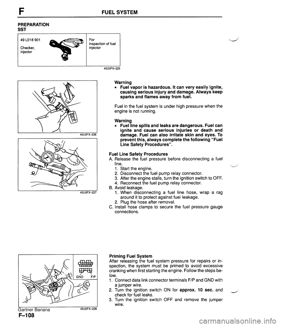
FUEL SYSTEM PREPARATION SST 49 LO1 8 901 For inspection of fuel Checker, injector injector Warning Fuel vapor is hazardous. It can very easily ignite, causing serious injury and damage. Always keep sparks and flames away from fuel. Fuel in the fuel system is under high pressure when the engine is not running. Warning Fuel line spills and leaks are dangerous. Fuel can ignite and cause serious injuries or death and damage. Fuel can also irritate skin and eyes. To prevent this, always complete the following "Fuel Line Safety Procedures". Fuel Line Safety Procedures A. Release the fuel pressure before disconnecting a fuel line. xd 1 . Start the engine. 2. Disconnect the fuel pump relay connector. 3. After the engine stalls, turn the ignition switch to OFF. 4. Reconnect the fuel pump relay connector. B. Avoid leakage. 1. When disconnecting a fuel line hose, wrap a rag around it to protect against fuel leakage. 2. Plug the hose after removal. C. Install hose clamps to secure the fuel pressure gauge connections. Priming Fuel System After releasing the fuel system pressure for repairs or in- spection, the system must be primed to avoid excessive cranking when first starting the engine. Follow the steps be- low. 1. Connect data link connector terminals F/P and GND with a jumper wire. 2. Turn the ignition switch ON for approx. 10 sec. and - check for fuel leaks. 3. Turn the ignition switch OFF and remove the jumper wire. Gartner Banana
Page 351 of 1708

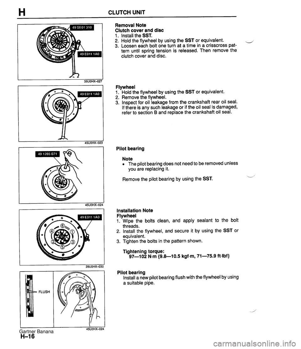
H CLUTCH UNIT Removal Note Clutch cover and disc 1 . Install the SST. 2. Hold the flywheel by using the SST or equivalent. e 3. Loosen each bolt one turn at a time in a crisscross pat- tern until spring tension is released. Then remove the clutch cover and disc. Flywheel 1. Hold the flywheel by using the SST or equivalent. 2. Remove the flywheel. 3. Inspect for oil leakage from the crankshaft rear oil seal. If there is any such leakage or if the oil seal is damaged, refer to section B and replace the crankshaft oil seal. Pilot bearing Note The pilot bearing does not need to be removed unless you are replacing it. Remove the pilot bearing by using the SST. L' Installation Note Flywheel 1. Wipe the bolts clean, and apply sealant to the bolt threads. 2. Install the flywheel, and secure it by using the SST or equivalent. 3. Tighten the bolts in the pattern shown. Tightening torque: 97-1 02 N.m (9.8-1 0.5 kgf.m, 71-75.9 ft-lbf) Pilot bearing Install a new pilot bearing flush with the flywheel by using a suitable pipe. Gartner Banana
Page 371 of 1708

TRANSMISSION 1. Snap ring 2. Washer 3. Retaining ring b 4. C-washer 5. Mainshaft rear bearing Disassembly Note . below Inspection ... page J-25 6. Retaining ring 7. C-washer 8. Thrust lock washer 9. Steel ball 10. Locknut (Countershaft) Disassembly Note ................ below 11. Countershaft rear bearing Disassembly Note ........... page J-18 Inspection ... page J-25 12. Counter 5th gear Inspection ... page J-23 13. Spacer 14. 5th gear 15. 5th synchronizer ring Inspection ... page J-24 16. Locknut (Mainshaft) Disassembly Note ........... page J-18 17. Clutch hub assembly (5thIReverse) Inspection ... page J-23 18. Reverse synchronizer ring Inspection ... page J-24 19. Reverse gear Inspection ... page J-23 20. Bearing Inspection ... page J-25 21. Bearing race 22. Washer 23. Counter reverse gear Inspection ... page J-23 24. Main drive gear bearing Disassembly Note ........... page J-18 Inspection ... page J-25 26. Countershaft front bearing Disassembly Note ........... page J-18 Inspection ... page J-25 27. Bearing housing assembly Disassembly Note ........... page J-18 Disassembly page J-20 28. Mainshaft gear assembly 29. Main drive gear Inspection ... page J-23 30. 4th synchronizer ring Inspection ... page J-24 31. Bearing Inspection ... page J-25 32. Washer 33. Countershaft Inspection ... page J-23 34. Spacer 35. Synchronizer key springs 36. Clutch hub sleeve 37. Synchronizer key . . Inspection ... page J-23 25. Snap ring 38. Clutch hub 45UOJX-012 Disassembly note Mainshaft rear bearing Remove the mainshaft rear bearing by using the SST. Locknut (Countershaft) 1. Shift the clutch hub sleeves into 1 st and Reverse gears to lock the rotation of the mainshaft. 2. Use a suitable tool to uncrimp the tabs of the locknut. 3. Connect the SST to the mainshaft and secure it in a vise. 4. Remove the locknut. Gartner Banana