Page 259 of 1708
FUEL SYSTEM Fuel Line Pressure Inspection Warning Fuel line spills and leaks are dangerous. Fuel can ignite and cause serious injuries or death and damage. Fuel can also irritate skin and eyes. To prevent this, always complete the "Fuel Line Safety Procedures" on page F-108. 1. Disconnect the negative battery terminal. 2. Install a fuel pressure gauge between the fuel pipe and the fuel main hose. (Install clamps as shown.) 3. Connect the negative battery terminal. 4. Connect data link connector terminals F/P and GND with a jumper wire. 5. Turn the ignition switch ON. 6. Measure the fuel line pressure. Fuel line pressure: 265-31 4 kPa {2.7-3.2 kgf/cm2, 38-46 psi) Pressure low- Check fuel pump maximum pressure. (Refer to page F-115.) If as specified, fuel line or fuel filter might be clogged or restricted. Pressure high- Replace the pressure regulator. (Refer to page F-118.) Gartner Banana
Page 261 of 1708

FUEL SYSTEM 1. Fuel filler hoses 7. Rear crossmem ber assembly 2. Fuel hoses Removal Note ............. page F-112 3. Evaporative hoses 8. Fuel tank unit 4. Fuel filter bolts 9. Two-way check valve ~4 Removal Note ............. page F-112 10. Fuel vapor valve 5. Brake pipe joint 11. Fuel pump Removal Note ............. page F-112 6. Battery cable Removal Note ............. page F-112 Removal note Fuel filter bolts 1. Remove the fuel filter cover. 2. Remove the fuel filter bolts. (MT) 3. Remove the fuel filter nuts. (AT) 4. Remove the fuel filter with the fuel hoses still connected. Brake pipe joint 1. Remove the brake pipe joint nuts. 2. Remove the brake pipe joint with the brake pipe and brake hose still connected. Battery cable Remove the battery cable clamp as shown in the figure. Rear crossmember assembly 1. Support the rear crossmember assembly with a trans- mission jack. 2. Remove the rear crossmember mounting bolts and nuts. 3. Lower the rear crossmember assembly. Gartner Banana
Page 263 of 1708

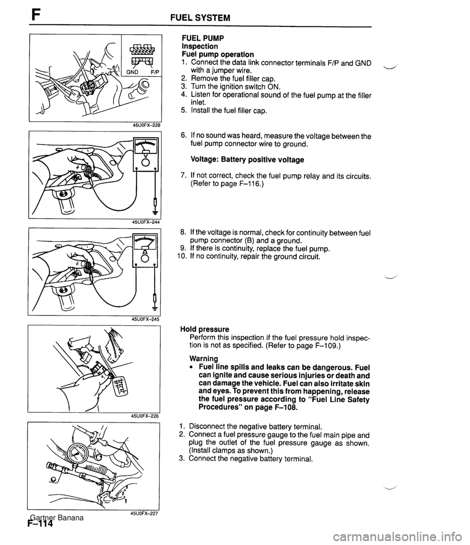
F FUEL SYSTEM FUEL PUMP Inspection Fuel pump operation 1. Connect the data link connector terminals F/P and GND , with a jumper wire. 2. Remove the fuel filler cap. 3. Turn the ignition switch ON. 4. Listen for operational sound of the fuel pump at the filler inlet. 5. Install the fuel filler cap. 6. If no sound was heard, measure the voltage between the fuel pump connector wire to ground. Voltage: Battery positive voltage 7. If not correct, check the fuel pump relay and its circuits. (Refer to page F-116.) 8. If the voltage is normal, check for continuity between fuel pump connector (6) and a ground. 9. If there is continuity, replace the fuel pump. 10. If no continuity, repair the ground circuit. Hold pressure Perform this inspection if the fuel pressure hold inspec- tion is not as specified. (Refer to page F-109.) Warning Fuel line spills and leaks can be dangerous. Fuel can ignite and cause serious injuries or death and can damage the vehicle. Fuel can also irritate skin and eyes. To prevent this from happening, release the fuel pressure according to "Fuel Line Safety Procedures" on page F-108. 1. Disconnect the negative battery terminal. 2. Connect a fuel pressure gauge to the fuel main pipe and plug the outlet of the fuel pressure gauge as shown. (Install clamps as shown.) 3. Connect the negative battery terminal. Gartner Banana
Page 264 of 1708

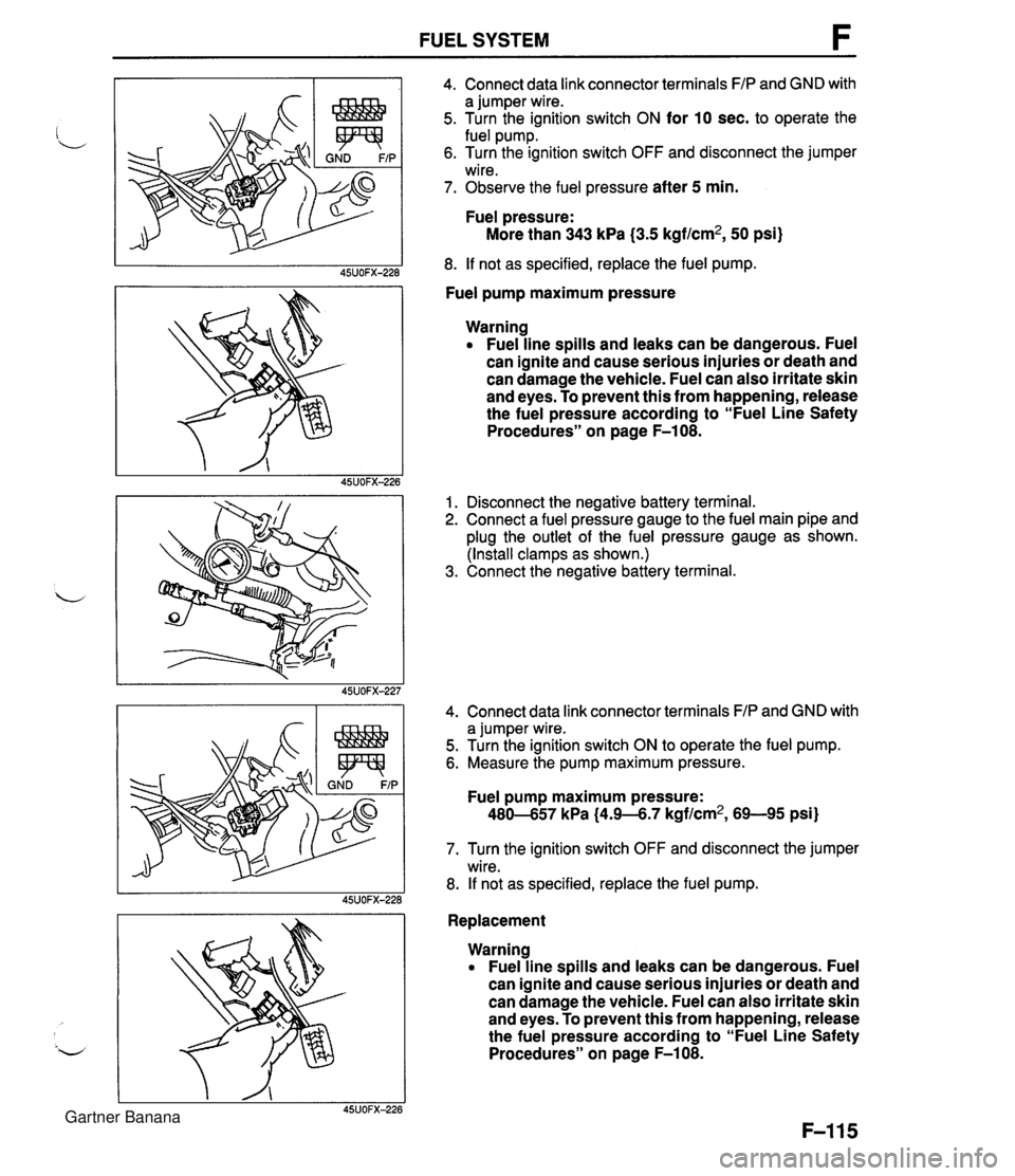
FUEL SYSTEM 4. Connect data link connector terminals FIP and GND with a jumper wire. 5. Turn the ignition switch ON for 10 sec. to operate the fuel pump. 6. Turn the ignition switch OFF and disconnect the jumper wire. 7. Observe the fuel pressure after 5 min. Fuel pressure: More than 343 kPa (3.5 kgf/cm2, 50 psi) 8. If not as specified, replace the fuel pump. Fuel pump maximum pressure Warning Fuel line spills and leaks can be dangerous. Fuel can ignite and cause serious injuries or death and can damage the vehicle. Fuel can also irritate skin and eyes. To prevent this from happening, release the fuel pressure according to "Fuel Line Safety Procedures" on page F-108. 1. Disconnect the negative battery terminal. 2. Connect a fuel pressure gauge to the fuel main pipe and plug the outlet of the fuel pressure gauge as shown. (Install clamps as shown.) 3. Connect the negative battery terminal. 4. Connect data link connector terminals FIP and GND with a jumper wire. 5. Turn the ignition switch ON to operate the fuel pump. 6. Measure the pump maximum pressure. Fuel pump maximum pressure: 480-657 kPa (4.9-6.7 kgf/cm2, 69-95 psi) 7. Turn the ignition switch OFF and disconnect the jumper wire. 8. If not as specified, replace the fuel pump. Replacement Warning Fuel line spills and leaks can be dangerous. Fuel can ignite and cause serious injuries or death and can damage the vehicle. Fuel can also irritate skin and eyes. To prevent this from happening, release the fuel pressure according to "Fuel Line Safety Procedures" on page F-108. Gartner Banana
Page 265 of 1708
FUEL SYSTEM -- FUEL TANK GAUGE SENDER UNIT SIDE FUEL PUMP 45UOFX-256 1. Remove the rear package trim. 2. Remove the service hole cover. 3. Remove the fuel pump cover. 4. Disconnect the fuel pump connector. 5. Disconnect the fuel hoses. 6. Remove the fuel pump and fuel tank gauge sender unit assembly. 7. Remove the fuel pump. 8. Install in the reverse order of removal, referring to Instal- lation note. Installation note O-ring set 1. Use a new O-ring set. (O-ring, cap, and spacer) 2. Apply oil or fuel to the O-ring set before installing. 3. To confirm sealing of the O-ring, after assembling the fuel pump and fuel tank gauge sender unit, blow air through the fuel main pipe and verify that no air flows. If air flows the check ball may be stuck. Shake the fuel pump 2 or 3 times and recheck. Fuel pump After installing the fuel pump to the bracket, pull down the fuel pump down so that it is tight against the bracket. Gartner Banana
Page 266 of 1708
FUEL SYSTEM F FUEL PUMP RELAY Inspection Apply battery positive voltage and a ground to the termi- nals below and check the fuel pump relay operation as described. If not as specified, replace the fuel pump relay. B+: Battery positive voltage Replacement 1. Remove the undercover. B+ A 2. Remove the fuel pump relay. 3. Install in the reverse order of removal. Grounded B Correct result C - E: Continuity Gartner Banana
Page 267 of 1708

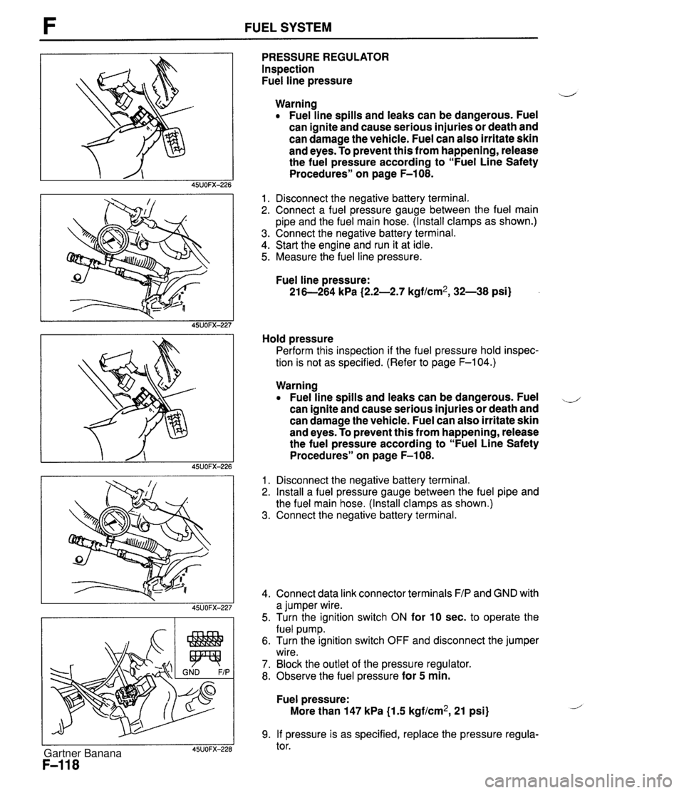
F FUEL SYSTEM PRESSURE REGULATOR Inspection Fuel line pressure d Warning Fuel line spills and leaks can be dangerous. Fuel can ignite and cause serious injuries or death and can damage the vehicle. Fuel can also irritate skin and eyes. To prevent this from happening, release the fuel pressure according to "Fuel Line Safety Procedures" on page F-108. 1. Disconnect the negative battery terminal. 2. Connect a fuel pressure gauge between the fuel main pipe and the fuel main hose. (Install clamps as shown.) 3. Connect the negative battery terminal. 4. Start the engine and run it at idle. 5. Measure the fuel line pressure. Fuel line pressure: 21 6-264 kPa (2.2-2.7 kgf/cm2, 32-38 psi) Hold pressure Perform this inspection if the fuel pressure hold inspec- tion is not as specified. (Refer to page F-104.) Warning Fuel line spills and leaks can be dangerous. Fuel ,-, can ignite and cause serious injuries or death and can damage the vehicle. Fuel can also irritate skin and eyes. To prevent this from happening, release the fuel pressure according to "Fuel Line Safety Procedures" on page F-108. 1. Disconnect the negative battery terminal. 2. Install a fuel pressure gauge between the fuel pipe and the fuel main hose. (Install clamps as shown.) 3. Connect the negative battery terminal. 4. Connect data link connector terminals F/P and GND with a jumper wire. 5. Turn the ignition switch ON for 10 sec. to operate the fuel pump. 6. Turn the ignition switch OFF and disconnect the jumper wire. 7. Block the outlet of the pressure regulator. 8. Observe the fuel pressure for 5 min. Fuel pressure: More than 147 kPa {I .5 kgf/cm2, 21 psi) 9. If pressure is as specified, replace the pressure regula- tor. Gartner Banana
Page 281 of 1708

FUEL EVAPORATIVE SYSTEM I GROUND I PURGE SOLENOID VALVE On-vehicle lnspection 1. Warm up the engine to normal operating temperature. 2. Run the engine at idle. d 3. Disconnect the vacuum hose from the purge solenoid valve and verify that no vacuum is felt at the purge sole- noid valve. 4. If not as specified, check the purge solenoid valve. lnspection 1. Disconnect the vacuum hoses from the purge solenoid valve. 2. Verify that no air flows through the purge solenoid valve. 3. Disconnect the purge solenoid valve connector and con- nect battery positive voltage and a ground to the termi- nals of the purge solenoid valve. 4. Verify that the air flows through the valve. 5. If not as specified, replace the purge solenoid valve. TWO-WAY CHECK VALVE lnspection 1. Remove the valve. 2. Check the operation of the valve with a vacuum pump. INSTALLATION DIRECTION Specification I Apply approx. 15 mmHg i0.59 inHg} vacuum at port A 1 Airflow I 1 Agply apgrox. 44 mmH~ (1.73 inHd vacuum at Port 6 1 Airflow 1 3. If not as specified, replace the two-way check valve. THREE-WAY CHECK VALVE lnspection 1. Remove the valve and plug the port C. 2. Check operation of the valve with a vacuum pump. Specification 3. If not as specified, replace the three-way check valve. Apply approx. 37 mmHg {I -46 inHg} vacuum at port A Apply approx. 70 mmHg (2.76 inHg} vacuum at port I3 Airflow Airflow -d Gartner Banana