1994 MAZDA MX-5 battery location
[x] Cancel search: battery locationPage 3 of 1708

GENERAL INFORMATION SAFETY INFORMATION ...................... GI- 2 LUBRICANTS .............................. GI- 2 JACKING POSITIONS ...................... GI- 2 SAFETY STAND POSITIONS ................ GI- 2 VEHICLE LIFT POSITIONS .................. GI- 3 DYNAMOMETER ........................... GI- 3 COMPRESSED AIR ........................ GI- 3 HOW TO USE THIS MANUAL ................. GI- 4 ADVISORY MESSAGES .................... GI- 4 PREPARATION ............................ GI- 4 REPAIR PROCEDURE ...................... GI- 4 SYMBOLS ................................. GI- 5 IDENTIFICATION NUMBER LOCATIONS ....... GI- 6 UNITS ...................................... GI- 6 ABBREVIATIONS ............................ GI- 7 SAE STANDARDS ........................... GI- 8 FUNDAMENTAL PROCEDURES ............... GI-11 PROTECTION OF THE VEHICLE ............ GI-11 PREPARATION OF TOOLS AND MEASURING EQUIPMENT ............................. GI-11 SPECIAL TOOLS ........................... GI-11 REMOVALOF PARTS ...................... GI-11 DISASSEMBLY ............................ GI-11 REASSEMBLY ............................. GI-1 2 ADJUSTMENTS ............................ GI-13 RUBBER PARTS AND TUBING .............. GI-13 HOSE CLAMPS ............................ GC13 TORQUE FORMULAS ...................... GI-13 VISE ...................................... GI-13 ELECTRICAL TROUBLESHOOTING TOOLS ... GI-14 TEST LIGHT ............................... GI-14 JUMPER WIRE ............................ GC14 VOLTMETER .............................. GI-14 OHMMETER ............................... GI-14 ELECTRICAL PARTS ......................... GI-1 4 BATTERY ................................. GI-1 4 BATTERY CABLE .......................... GI-1 5 CONNECTORS ............................ GI-15 TERMINALS ............................... GI-16 SENSORS. SWITCHES. AND RELAYS ....... GI-17 WIRING HARNESS ......................... GI-17 FUSE ..................................... GI-17 INSTALLATION OF MOBILE TWO-WAY RADIO SYSTEM ................................... GI-18 AUDIO ANTITHEFT SYSTEM ................. GI-18 TOWING .................................... GI-19 45UGIX-001 Gartner Banana
Page 857 of 1708

T FUSE DESCRIPTION Main Fuse Block The main fuse block is located on the right side of the engine compartment and contains nine fuses and two relays. -1 Fuse Box Fuse block No.1 is located above the dead pedal of the driver side. The fuse box cover shows the speci- fied fuse locations. A circuit breaker is included in the fuse box to protect the heater blower motor circuit. Fuse block No.2 is located to the side of the battery in the trunk compartment. 45UOTX-016 REPLACEMENT Caution Determine and correct the cause of a burnt fuse before replacing it. If the fuse is replaced before doing this, it may burn again. Plate type 1. Disconnect the negative battery cable. 2. Replace the failed fuse with the fuse puller. 3. Reconnect the negative battery cable. Cartridge-type 80A fuse (Black) 1. Disconnect the negative battery cable. 2. Remove the fuse block mounting nuts, and remove the service cover. 3. Remove the fuse installation bolts, and pull out the fuse. 4. Install the new fuse and the fuse installation bolts. 5. Install the main fuse block. 6. Reconnect the negative battery cable. Gartner Banana
Page 936 of 1708

REAR WINDOW DEFROSTER T u Symptom: Rear window defroster does not operate. 9MUOTX-232 Step 1 1. Check the following fuses. I Fuse Amperage I Location I 2. If all the fuses are OK, go to Step 2. 3. If a fuse is burned out, replace it. Check and repair the wire harness, if necessary. R.DEF HEATER -- M: Continuity 20A 30A Step 2 1. Disconnect the rear window defroster relay. 2. Apply battery positive voltage and check for continuity between terminals of the relay. B+: Battery positive voltage 3. If correct install the rear window defroster relay and go to Step 3. 4. If not as specified, replace the rear window defroster relay. Fuse box No.2 Main fuse block Step 1 2 C Terminal D 0 GND B 0 B+ A 0 C 0 Gartner Banana
Page 1002 of 1708

SRS AIR BAG SYSTEM T COMPONENT DESCRIPTION Component Air bag module Function Air bag system warning light Deploys air bag when current flows to integrated igniter Light illuminates or flashes if malfunction occurs in air bag system I EE with S-sensor, completes Circuit Clock spring I Ensures uninterrupted electrical connec- tion to air bag module while allowing turning of steering wheel Activated(closed) when crash impact de- Crash sensor Diagnostic module to infktor Activated(closed) when crash impact de- S-sensor 1 Monitors com~onents and harnesses in tected Acting with D-sensor, completes circuit to inflator Remark Located in instrument cluster Location: Driver side . . . . . . . . in steering wheel hub Passenger side . . . above the glove compartment Part of combination switch Located in front part of vehicle(left, right, and center) Located behind heater unit in passenger compartment Contains back-up battery air bag system Indicates system malfunction by flashing or illuminating air bag system warning light If warning light is bunt, sounds warning buzzer Detects short circuit between air bag module and ground or crash sensor rnal- function and melts system fuse to pre- vent unintended air bag deployment Gartner Banana
Page 1067 of 1708

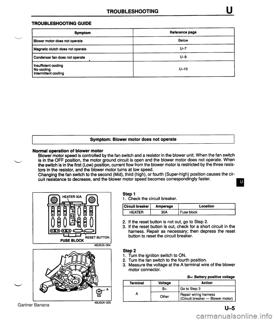
TROUBLESHOOTING u TROUBLESHOOTING GUIDE I Symptom Blower motor does not operate Reference page Below Magnetic clutch does not operate I U-7 Condenser fan does not operate e Symptom: Blower motor does not operate I U-9 Insufficient cooling No cooling Intermittent cooling Normal operation of blower motor Blower motor speed is controlled by the fan switch and a resistor in the blower unit. When the fan switch L is in the OFF position, the motor ground circuit is open and the blower motor does not operate. When the switch is in the first (Low) position, current flow from the blower motor is restricted by the three resis- tors in the resistor, and the blower motor turns at low speed. Changing the fan switch to the second (Mid), third (high), or fourth (Super-high) position causes the cir- cuit resistance to decrease, and the blower motor speed becomes correspondingly faster. I l U-10 (-1 (rn) I I I RESET BUTTON FUSE BLOCK Step 1 1. Check the circuit breaker. 2. If the reset button is not out, go to Step 2. 3. If the reset button is out, check for a short circuit in the harness. Repair as necessary; then depress the reset button to reset the circuit breaker. circuit breaker HEATER Step 2 1. Turn the ignition switch to ON. 2. Turn the fan switch to the fourth position. 3. Measure the voltage at the A terminal wire of the blower motor connector. B+: Battery positive voltage I Terminal I Voltage Action I Amperage 30A Location Fuse block A U-5 Bt Other Go to Step 3 Repair wiring harness (Circuit breaker - Blower motor) Gartner Banana
Page 1069 of 1708

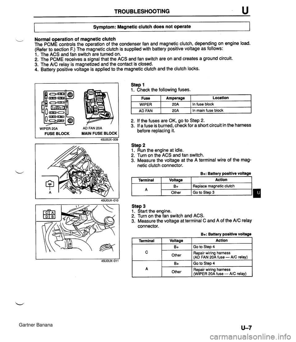
TROUBLESHOOTING u 7- Symptom: Magnetic clutch does not operate I Normal operation of magnetic clutch The PCME controls the operation of the condenser fan and magnetic clutch, depending on engine load. (Refer to section F.) The magnetic clutch is supplied with battery positive voltage as follows: 1. The ACS and fan switch are turned on. 2. The PCME receives a signal that the ACS and fan switch are on and creates a ground circuit. 3. The A/C relay is magnetized and the contact is closed. 4. Battery positive voltage is applied to the magnetic clutch and the clutch locks. WIPER 20A AD FAN 20A FUSE BLOCK MAIN FUSE BLOCK Step 1 1. Check the following fuses. I Fuse I Amperage I Location I I I . - I WIPER I 20A 1 In fuse block I I AD FAN I 20A 1 In main fuse block I 2. If the fuses are OK, go to Step 2. 3. If a fuse is burned, check for a short circuit in the harness before replacing it. Step 2 1. Run the engine at idle. 2. Turn on the ACS and fan switch. 3. Measure the voltage at the A terminal wire of the mag- netic clutch connector. B+: Battery positive voltage I Terminal I Voltage I Action 1 Step 3 1. Start the engine. 2. Turn on the fan switch and ACS. 3. Measure the voltage at terminal C and A of the A/C relay connector. B+: Batterv positive voltaae - -- A 1 Terminal I V0lta0e 1 Action I I C I Other I Repair wiring harness (AD FAN 20A fuse - AIC relay) I B+ Other I 1. -. B+ I GO to step 4 Replace magnetic clutch Go to Step 3 I A 1 Other I Repair wiring harness (WIPER 20A fuse - AIC relay) I Gartner Banana