Page 3 of 1708

GENERAL INFORMATION SAFETY INFORMATION ...................... GI- 2 LUBRICANTS .............................. GI- 2 JACKING POSITIONS ...................... GI- 2 SAFETY STAND POSITIONS ................ GI- 2 VEHICLE LIFT POSITIONS .................. GI- 3 DYNAMOMETER ........................... GI- 3 COMPRESSED AIR ........................ GI- 3 HOW TO USE THIS MANUAL ................. GI- 4 ADVISORY MESSAGES .................... GI- 4 PREPARATION ............................ GI- 4 REPAIR PROCEDURE ...................... GI- 4 SYMBOLS ................................. GI- 5 IDENTIFICATION NUMBER LOCATIONS ....... GI- 6 UNITS ...................................... GI- 6 ABBREVIATIONS ............................ GI- 7 SAE STANDARDS ........................... GI- 8 FUNDAMENTAL PROCEDURES ............... GI-11 PROTECTION OF THE VEHICLE ............ GI-11 PREPARATION OF TOOLS AND MEASURING EQUIPMENT ............................. GI-11 SPECIAL TOOLS ........................... GI-11 REMOVALOF PARTS ...................... GI-11 DISASSEMBLY ............................ GI-11 REASSEMBLY ............................. GI-1 2 ADJUSTMENTS ............................ GI-13 RUBBER PARTS AND TUBING .............. GI-13 HOSE CLAMPS ............................ GC13 TORQUE FORMULAS ...................... GI-13 VISE ...................................... GI-13 ELECTRICAL TROUBLESHOOTING TOOLS ... GI-14 TEST LIGHT ............................... GI-14 JUMPER WIRE ............................ GC14 VOLTMETER .............................. GI-14 OHMMETER ............................... GI-14 ELECTRICAL PARTS ......................... GI-1 4 BATTERY ................................. GI-1 4 BATTERY CABLE .......................... GI-1 5 CONNECTORS ............................ GI-15 TERMINALS ............................... GI-16 SENSORS. SWITCHES. AND RELAYS ....... GI-17 WIRING HARNESS ......................... GI-17 FUSE ..................................... GI-17 INSTALLATION OF MOBILE TWO-WAY RADIO SYSTEM ................................... GI-18 AUDIO ANTITHEFT SYSTEM ................. GI-18 TOWING .................................... GI-19 45UGIX-001 Gartner Banana
Page 17 of 1708
ELECTRICAL PARTS GI BATTERY CABLE Before disconnecting connectors or removing electrical parts, disconnect the negative battery cable. CONNECTORS Data Link Connector Insert the probe into the service hole when connecting a jumper wire to the data link connector. Caution Inserting a jumper wire probe into the data link connector terminal may damage the terminal. Power Connector The special power connector in the engine compartment (Blue: 1 -pin) supplies battery positive voltage for exter- nally powered test equipment. Caution Do not ground the power connector terminal; the 20A wiper fuse will be burned. Disconnecting Connectors When disconnecting two connectors, grasp the connec- tors, not the wires. Connectors can be disconnected by pressing or pulling the lock lever as shown. Gartner Banana
Page 1019 of 1708

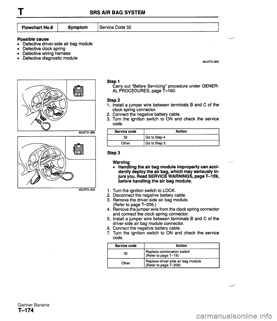
T SRS AIR BAG SYSTEM I Flowchart No.8 I Symptom I Service Code 32 I Possible cause a Defective driver-side air bag module a Defective clock spring Defective wiring harness a Defective diagnostic module Step 1 Carry out "Before Servicing" procedure under GENER- AL PROCEDURES, page T-160. Step 2 1. Install a jumper wire between terminals B and C of the clock spring connector. 2. Connect the negative battery cable. 3. Turn the ignition switch to ON and check the service code. I Other I Go to Step 3 I Service code 32 Step 3 Action Go to Step 4 Warning -- a Handling the air bag module improperly can acci- dently deploy the air bag, which may seriously in- jure you. Read SERVICE WARNINGS, page T-159, before handling the air bag module. Turn the ignition switch to LOCK. Disconnect the negative battery cable. Remove the driver-side air bag module. (Refer to page T-206.) Remove the jumper wire from the clock spring connector and connect the clock spring connector. Install a jumper wire between terminals B and C of the driver-side air bag module connector. Connect the negative battery cable. Turn the ignition switch to ON and check the service code. I Service code Action I 32 Replace combination switch (Refer to page T-19) Other Replace driver-side air bag module (Refer to page T-206) Gartner Banana
Page 1021 of 1708

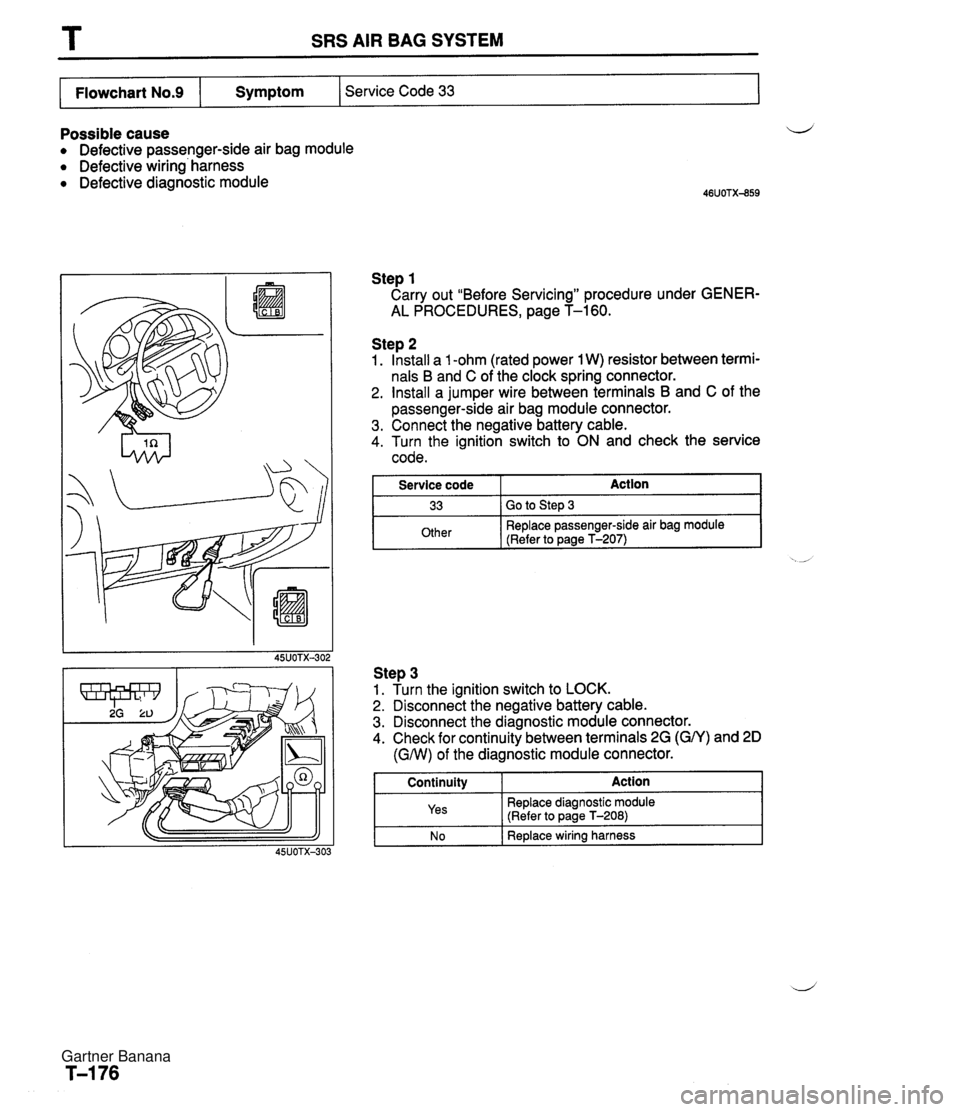
T SRS AIR BAG SYSTEM Possible cause Defective passenger-side air bag module Defective wiring' harness Defective diagnostic module Step 1 Carry out "Before Servicing" procedure under GENER- AL PROCEDURES, page T-160. Service Code 33 Flowchart No.9 Step 2 1. Install a 1 -ohm (rated power 1 W) resistor between termi- nals B and C of the clock spring connector. 2. Install a jumper wire between terminals B and C of the passenger-side air bag module connector. 3. Connect the negative battery cable. 4. Turn the ignition switch to ON and check the service code. I Service code Action I Symptom Step 3 1. Turn the ignition switch to LOCK. 2. Disconnect the negative battery cable. 3. Disconnect the diagnostic module connector. 4. Check for continuity between terminals 2G (GN) and 2D 33 Other (GNV) of the diagnostic module connector. ' Go to Step 3 Replace passenger-side air bag module (Refer to page T-207) i I N o I Replace wiring harness Continuity Yes Action Replace diagnostic module (Refer to page T-208) Gartner Banana