Page 295 of 1708

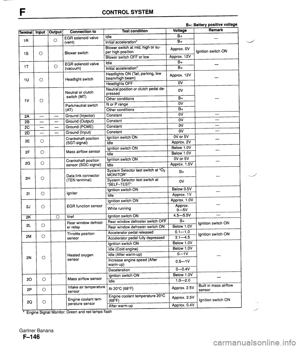
F CONTROL SYSTEM B+: Battery positive voltage Connection to 1 Test condition 1 Voltage I Remark I -- EGR solenoid valvi Idle B+ Blower switch -- EGR solenoid valve (vacuum) :vent) Initial acceleration* Blower switch at mid, high or su- per high position Blower switch OFF or low Headlight switch Neutral or clutch switch (MT) B+ Idle ParWneutral switch (AT) Ground (Injector) Ground (Output) Ground (PCME) Approx. OV - Approx. 12V B+ Headlights ON (Tail, parking, low beamfhigh beam) Headlights OFF Neutral position or clutch pedal de- pressed Other conditions Ground (Input) Crankshaft position (SGT-signal) Ignition switch ON N or fJ range Other conditions Constant Constant Constant -. Mass airflow sensor .. . . EGR function sensor I while running Approx. 0-5v Initial acceleration* Approx, 2V OV ov B+ Constant Ignition switch ON Idle Crankshaft position sensor (SGC-signal) Data link connector (TEN terminal) Igniter I I I Vre f I lanition switch ON 1 4.5-5.9.' 1 - B+ - OV B+ OV OV OV Ignition switch ON Idle - - - OV OV or 5V ADD~OX. 2V - - Ignition switch ON Idle System Selector test switch at "02 MONITOR" System Selector test switch at "SELF-TEST" Ignition switch ON Idle lanition switch ON I . . I I 1 Ignition switch ON I Below 1 .OV I I - - . . Below 1 .OV Below 1 .OV ear window defrost- er relay Throttle position sensor Heated oxygen sensor - OV or 5V Approx. 1.5V B+ ov Below 0.5V Approx. 1 V Approx. 1 .OV - - - " Rear window defroster switch OFF Rear window defroster switch ON Accelerator pedal released Accelerator ~edal fullv de~ressed Mass airflow sensor B+ Below 1 .OV 0.1-1 .o 3.14.5 Intake air temperature sensor Engine coolant tem- perature sensor lgnition switch ON lgnition switch ON Ignition switch ON Idle ireen and red lamps flash At 200C {680Fj Engine coolant temperature 20°C {680F) After warm-up Below 1 .OV 1 .O-2.0 - Approx. 2.5V Approx. 2.5V Approx. 0.4V Built in mass airflow lgnition switch ON Gartner Banana
Page 865 of 1708
T SWITCH 1 FLASHER UNlT TR CRUISE CONTROL UNlT u Inspection 1. Disconnect the negative battery cable. 2. Remove the knee protector. 3. Disconnect the combination switch connector. i 4. Check for continuity between the terminals described by using an ohmmeter. 5. If the continuity is not as specified, replace the combina- tion switch as an assembly. Lights, dimmer, and passing switch Position Low beam Headlight High beam Passing Tail, Parking W: Continuity Turn signal switch Terminal E I HL I HU (TNSJHEADI BA I B I Switch m: Continuity Left Right Windshield wiper and washer switch O--O : Continuity d Terminal 0 0 Cruise control switch FU I TL TR 0 0 I Position SETICOAST RESUME/ACCEL Terminal SE I RE W: Continuity 0 E 0 0 0 ,i Gartner Banana
Page 888 of 1708
LIGHTING SYSTEM T LAY Step 2 1. Turn the headlight switch ON. 2. Measure the voltage at the following terminal-wires of the headlight relay connector. B+: Battery positive voltage Other Action Go to Step 3 Check B terminal Go to Step 6 Check A terminal Check D terminal Repair wirring harness Repair wiring harness (HEAD 30A - Headliclht relav) I Step 3 1. Turn the headlight switch ON. 2. Measure the voltaae at the followinn terminal-wires of - the headlight switch connector. B+: Battery positive voltage Termlnal I Switch position I Voltage / Action I Check I terminal switch) Low beam G B+ Other - Go to Step 4 Replace combination switch High beam Step 4 1. Check the headlight bulbs. 2. If a bulb is burned, replace it. 3. If the bulbs are OK, go to Step 5. B+ Other Go to Step 4 Replace combination switch Gartner Banana
Page 889 of 1708
T LIGHTING SYSTEM Step 5 1. Disconnect the headlight connectors. 2. Turn the headlight switch on. 3. Measure the voltage at the following terminal wires. d B+: Battery positive voltage Switch position Low beam High beam Voltage B+ Other B+ Action Repair wiring harness (Retractable headlight - GND) Repair wiring harness (Combination switch - Retract- able headlight) Repair wiring harness (Retractable headlight - GND) 1. ?urn the headlight switch on. 2. Measure the voltage at the following terminal wires of the combination switch connector. B+: Battery positive voltage Other Terminal Repair wiring harness (Combination switch - Retract- able headlight) Voltage Action B+ Check D terminal Repair wiring harness (Retractable headlight relay - Com- bination switch) D B+ Other Repair wiring harness (Combination switch - GND) Replace combination switch Gartner Banana
Page 890 of 1708
LIGHTING SYSTEM T I Symptom: Headlight does not illuminate (Right or left). I Step 1 1. Check the headlight bulbs. 2. If a bulb is burned, replace it. 3. If the bulbs are OK, go to Step 2. Step 2 1. Disconnect the headlight connector of the faulty side. 2. Turn the headlight switch on. 3. Measure the voltage at the following terminal wires. B+: Battery positive voltage Other IB(FVW) Highbeam Action Repair wiring harness (Retractable headlight - GND) Repair wiring harness (Combination switch - Retract- able headlight) Repair wiring harness (Retractable headlight - GND) Repair wiring harness (Combination switch - Retract- able headlight) Gartner Banana
Page 919 of 1708

T LIGHTING SYSTEM Step 3 1. Remove the column cover and disconnect the connec- tors of the headlight switch. 2. Check for continuity between the terminals of the head- Q light switch connector. Position I Terminal I I I I Headlight High beam I I 3. If not as specified, replace the combination switch. 4. If correct, repair wiring harness. (Headlight switch - DRL control unit) I Symptom: Daytime running lights (DRL) function does not cancel. OSUOTX-161 Headlight Low beam Step 1 1. Turn the ignition switch ON. 2. Verify the symptom by operating the following switches; the DRL should cancel. Go to the specified Step. Headlight switch. Hazard warning switch. Turn signal switch. Parking brake switch (lever pulled one notch). 0 1 0 0---0 : Continuity Symptom: DRL function not canceled when Headlight switch ON I Parking brake switch ON Step 5 I 05UOTX-163 Next Step Step 2 Hazard warning switch ON Turn signal switch ON Step 4 Step 4 4. If not as specified, go to Step 3. 5. If correct, replace the DRL control unit. Step 2 1. Turn on the ignition switch. 2. Turn on the headlight switch. 3. Check the voltage at the terminal wire C (WIR) of the DRL control unit connector. B+: Battery positive voltage J Terminal Voltage C (WIR) B+ Gartner Banana
Page 920 of 1708

LIGHTING SYSTEM T Step 3 1. Remove the column cover and disconnect the connec- tors of the headlight switch. 2. Check for continuity between the terminals of the head- light switch connector. Position I- Terminal 0---0: Continuity HL Headlight High beam Headlight Low beam 3. If not as specified, replace the combination switch. 4. If correct repair wiring harness. (Headlight switch - DRL control unit) B A 1. Turn on the ignition switch. 2. Turn on the headlight switch. 3. Check the voltage at the following terminal wires of the DRL control unit connector. 0 B+: Battery positive voltage I Terminal I Voltage I 0 I I 45UOTX-151 4. If not as specified, repair wiring harness. (Flasher unit - DRL control unit) 5. If correct, replace the DRL control unit. F (GIB) H (GN) Step 5 1. Turn on the ignition switch. 2. Pull the parking brake lever more than one notch. 3. Check the voltage at terminal wire B (R) of the DRL con- trol unit connector. Cycles B+ and OV Cycles B+ and OV 4. If not as specified, go to Step 6. 5. If correct, replace the DRL control unit. T-75 B+: Battery positive voltage I Terminal Voltage B IR1 B+ Gartner Banana
Page 1123 of 1708

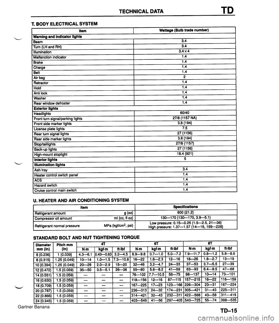
TECHNICAL DATA 1 Charge I 1.4 Belt 1.4 r. BODY ELECTRICAL SYSTEM 1 Air bag I 2 1 Retractor 1.4 Item Wattage (Bulb trade number) Hold Anti lock Wamlng and indicator lights 1.4 1.4 Washer Rear window defroster Beam Turn (LH and RH) Illumination Malfanction indicator Brake 1.4 1.4 I Exterior lights 3.4 3.4 3.4 x 4 1.4 1.4 Headlights Front turn signawparking lights Front side marker lights License plate lights Rear turn signal lights Rear side marker lights Stop/taillights Back-UP linhts High-mount stoplight I 18.4 (921) ACS 1 1.4 Hazard switch 1.4 60140 2718 (1 157 NA) 3.8 (1 94) 7.5 27 (1 1 56) 3.8 (1 94) 2718 {I 157) 27 (1 1561 Interior llahts - I lllumination lights I Cruise control main switch I 1.4 I 5 Ash tray U. HEATER AND AIR CONDITIONING SYSTEM I Item I Specit lcations I 3.4 Heater control switch ane el I 1.4 STANDARD BOLT AND NUT TIGHTENING TORQUE Refrigerant amount S (04 Compressor oil amount rnl {cc, fl oz) Refrigerant normal pressure MPa (kgflcm2, psi) 600 {2 1.21 130-1 70 {I 30-1 70,3.9-5.1) Low pressure: 0.154.25 (1 .5-2.5,21-361 Hiah Pressure: 1 37-1.57 (1 4--16, 199--228) Gartner Banana