Page 95 of 1708
INSPECTION I REPAIR ee x 25rnrn (1.0 in) min DAMAGE WEAR TIMING BELT Caution The following will damage the belt and shorten its life; Forcefully twisting it, turning it inside out, bending it, or allowing oil or grease on it. 1. Replace the timing belt if there is any oil or grease on it. 2. Check the timing belt for damage, wear, peeling, cracks, and hardening. Replace the timing belt if necessary. TENSIONER, IDLER Caution Using cleaning fluids or a steam cleaner to clean the tensioner can dissolve the grease in its sealed bearing. \.-' Check the tensioner and idler for smooth rotation and abnormal noise. Replace the tensioner or idler if neces- sary. TENSIONER SPRING Measure the free length of the tensioner spring. Replace the tensioner spring if necessary. Free length: 59.2mm (2.331 in) PULLEY Timing Belt Pulley, Camshaft Pulley Inspect the pulley teeth for wear, deformation, and other damage. Replace the pulley if necessary. Gartner Banana
Page 110 of 1708
ASSEMBLY B I I 35UOBX477 TIMING BELT Torque Specifications 3. Install the camshaft pulley lock bolts. 4. Hold the camshaft with a wrench. 5. Tighten the camshaft pulley lock bolt. Tightening torque: 50-40 N.m (5.0-6.2 kgf.m, 3744 ft-lbf) Gartner Banana
Page 111 of 1708

B ASSEMBLY TIMING MARK Timing Belt Pulley 1. lnstall the timing belt pulley. 2. lnstall the pulley woodruff key with the tapered side to- ward the oil pump body. d Idler lnstall the idler. Tightening torque: 38-51 N.m (3.8-5.3 kgf.m, 28-38 ftlbf) Tensioner and Tensioner Spring 1. lnstall the tensioner and the tensioner spring. 2. Temporarily secure the tensioner with the spring fully ex- tended. Timing Belt 1, Turn the crankshaft and align the timing belt pulley mark with the timing mark. Do not turn the crankshaft counter- clockwise. 2. Verify that the camshaft pulley marks are aligned with the seal plate marks. E for intake side and I for exhaust side. Do not turn the crankshaft counterclockwise. 3. lnstall the timing belt so that there is no looseness at the idler side or between the two camshaft pulleys. 4. lnstall the pulley boss and pulley lock bolt. 5. Turn the crankshaft two turns clockwise, and align the timing belt pulley mark with the timing mark. Do not turn the crankshaft counterclockwise. 6. Verify that the camshaft pulley marks are aligned with the seal plate marks. J If not aligned, remove the timing belt and repeat from tensioner installation. Gartner Banana
Page 112 of 1708

ASSEMBLY B r/ DEFLECTION %HECKING POINT , 7. Reverse the direction of the SST on the flywheel (MT) or drive plate (AT). 8. Tighten the pulley lock bolt. Tightening torque: 157-166 N-m (16-17 kgf.m, 116-122 ft-lbf) 9. Turn the crankshaft 1 and 516 turns clockwise, and align the timing belt pulley mark with the tension set mark. 10. Loosen the tensioner lock bolt to apply tension to the tim- ing belt. 11. Tighten the tensioner lock bolt. Tightening torque: 38-51 N-m (3.8-5.3 kgf-m, 28-38 ft4bf) 12. Turn the crankshaft 2 and 116 turns clockwise and verify that the timing marks are correctly aligned. 13. Measure the timing belt deflection by applying moderate pressure 98 N (10 kgf, 22 Ibf) midway between the two camshaft pulleys. If the deflection is not correct, repeat from step 7 above. Deflection: 9.0-11.5mm (0.36-0.45 in) at 98 N (1 0 kgf, 22 Ibf) Timing Belt Cover Install the lower, middle, and upper covers. Tightening torque: 7.9-10.7 N.m (80-110 kgf.cm, 70-95.4 in4bf) Gartner Banana
Page 123 of 1708

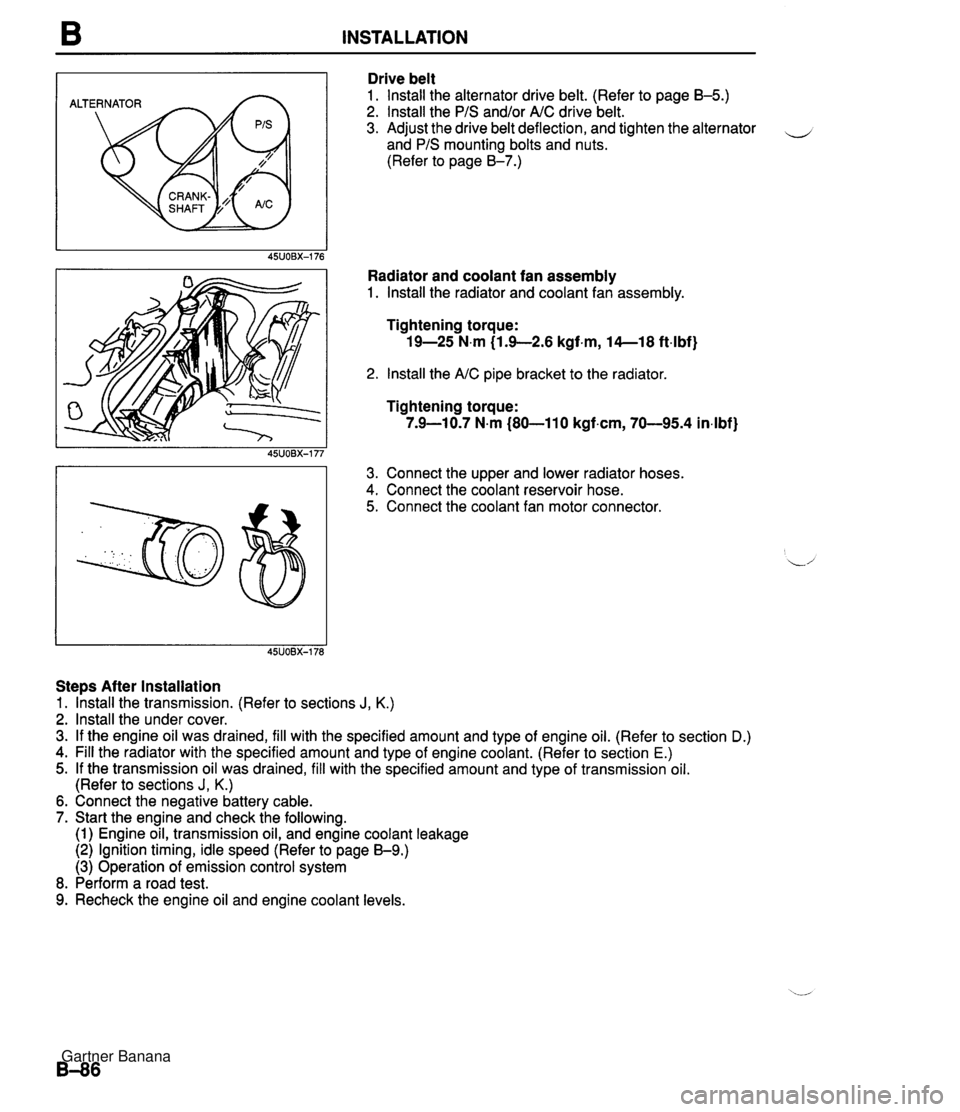
B INSTALLATION ALTERNATOR Drive belt 1. lnstall the alternator drive belt. (Refer to page B-5.) 2. lnstall the PIS and/or AIC drive belt. 3. Adjust the drive belt deflection, and tighten the alternator - and PIS mounting bolts and nuts. (Refer to page 8-7.) Radiator and coolant fan assembly 1. lnstall the radiator and coolant fan assembly. Tightening torque: 19-25 N.m (1.9-2.6 kgf.m, 14--18 ft4bf) 2. lnstall the AIC pipe bracket to the radiator Tightening torque: 7.9-10.7 N.m (80-110 kgf.cm, 70-95.4 in4bf) 3. Connect the upper and lower radiator hoses. 4. Connect the coolant reservoir hose. 5. Connect the coolant fan motor connector. Steps After Installation 1. lhstall the transmission. (Refer to sections J, K.) 2. lnstall the under cover. 3. If the engine oil was drained, fill with the specified amount and type of engine oil. (Refer to section D.) 4. Fill the radiator with the specified amount and type of engine coolant. (Refer to section E.) 5. If the transmission oil was drained, fill with the specified amount and type of transmission oil. (Refer to sections J, K.) 6. Connect the negative battery cable. 7. Start the engine and check the following. (1) Engine oil, transmission oil, and engine coolant leakage (2) Ignition timing, idle speed (Refer to page 59.) (3) Operation of emission control system 8. Perform a road test. 9. Recheck the engine oil and engine coolant levels. Gartner Banana
Page 139 of 1708

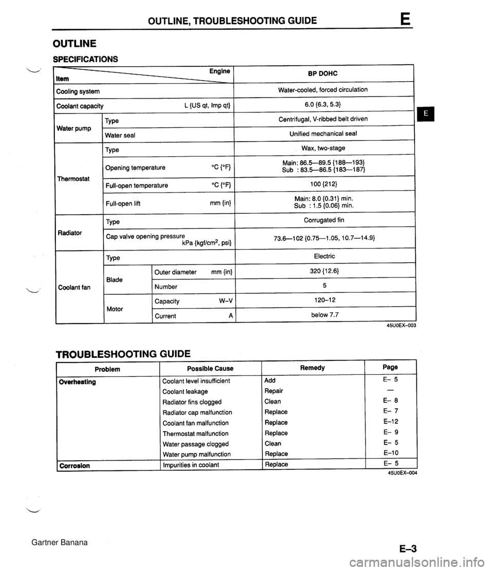
OUTLINE, TROUBLESHOOTING GUIDE OUTLINE SPECIFICATIONS Cooling system I Water-cooled, forced circulation I - - Engine Item - Water pump BP DOHC Coolant capacity L {US qt, Imp qt) TY ~e Thermostat 6.0 {6.3,5.3} Centrifugal, V-ribbed belt driven Radiator - Coolant fan Opening temperature Water seal TY pe Main: 86.5-89.5 {l 88-1 93) Sub : 83.5-86.5 (1 83-1 87) Unified mechanical seal Wax, two-stage I Full-open temperature "C ("F) 100 {212} 1 Full-open lift mm {in} Main: 8.0 (0.31) min. Sub : 1.5 (0.06) min. TY pe Corrugated fin Cap valve opening pressure kPa {kgf/cm2, psi} 1 TROUBLESHOOTING GUIDE Problem Electric 320 {l 2.6) 5 120-1 2 below 7.7 Type 45UOEX-003 Blade Motor Coolant level insufficient 1 Add Outer diameter mm {in) Number Capacity W-V Current A Possible Cause Coolant leakage 1 Repair Remedy Radiator fins clogged ( Clean Radiator cap malfunction 1 Replace Coolant fan malfunction 1 Replace Thermostat malfunction 1 Replace Water passage clogged 1 Clean Water pump malfunction Impurities in coolant Replace Replace Gartner Banana
Page 146 of 1708
WATER PUMP WATER PUMP REMOVAL I INSTALLATION 1. Disconnect the negative battery cable. 2. Drain the engine coolant. (Refer to page E-5 for WARNING and procedure) 3. Remove in the order shown in the figure, referring to Removal Note. 4. Install in the reverse order of removal. 1. Timing belt 4. Water pump Service . . . . . . . . . . . . . . . . . . . . . Section B Inspect for cracks, damaged mounting sur- 2. PIS oil pump face, bearing condition, and leakage. Removal Note . . . . . . . . . . . . . . page E-1 1 If the water pump is damage, replace it. 3. Water hose Do not repair it. 5. Water inlet pipe Gartner Banana
Page 225 of 1708

ENGINE TUNE-UP - TIMING LIGHT - 45UOFX422 GND Irnr Air Cleaner Element Inspection 1. Check the air cleaner element for excessive dirt and for oil and damage. Caution Cleaning the element with compressed air will re- duce the element's ability to filter the air. Don't use compressed air to clean the element. 2. Replace the element if necessary. ADJUSTMENT Preparation 1. Warm up the engine to normal operating temperature. 2. Turn all electric loads OFF. Headlight switch Blower switch Rear window defroster switch 3. Connect the SST to the data link connector. 4. Connect a timing light to the engine. 5. Connect a tachometer to the data link connector terminal IG- as shown. Ignition Timing 1. Perform Preparation. (Refer to above.) 2. Verify that the idle speed is within the specification; if not, adjust it. Idle speed 4 (Neutral): 800-900 (850 + 50) rpm [MT] (P range): 750-850 (800 & 50) rpm [AT] 3. Set switch A to position 1. 4. Set test switch to SELF TEST. 5. If the SST is not used, connect a jumper wire between the TEN terminal and the GND terminal of the data link connector. 6. Verify that the idle speed is within the specification. ldle speed (Ground the terminal TEN): 650-975 rpm 7. Verify that the timing mark (white) on the crankshaft pulley and the mark on the timing belt cover are aligned. lgnition timing: BTDC 9"-11" (10" & lo) Gartner Banana