Page 1063 of 1708
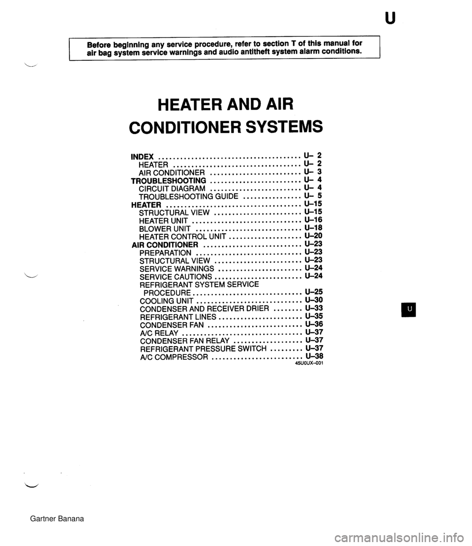
Before beginning any service procedure. refer to section T of this manual for I air bag system service warnings and audio antitheft system alarm conditions . HEATER AND AIR CONDITIONER SYSTEMS ....................................... INDEX U- 2 ................................... HEATER U- 2 AIR CONDITIONER ......................... U- 3 TROUBLESHOOTING ......................... U- 4 CIRCUIT DIAGRAM ......................... U- 4 TROUBLESHOOTING GUIDE ................ U- 5 ..................................... HEATER U-15 ........................ STRUCTURAL VIEW U-15 HEATER UNIT .............................. U-16 BLOWER UNIT ............................. U-18 HEATER CONTROL UNIT .................... U-20 AIR CONDITIONER ........................... U-23 PREPARATION ............................. U-23 STRUCTURAL Vl EW ........................ U-23 SERVICE WARNINGS ....................... U-24 SERVICE CAUTIONS ........................ U-24 REFRIGERANT SYSTEM SERVICE PROCEDURE .............................. U-25 COOLING UNIT ............................. U-30 CONDENSER AND RECEIVER DRIER ........ U-33 REFRIGERANT LINES ....................... U-35 CONDENSER FAN .......................... U-36 AIC RELAY ................................. U-37 ................... CONDENSER FAN RELAY U-37 REFRIGERANT PRESSURE SWITCH ......... U-37 NC COMPRESSOR ......................... U-38 45U0Ux-001 Gartner Banana
Page 1065 of 1708
INDEX u AIR CONDITIONER 1. Cooling unit 5. Condenser fan relay ................... Removal 1 Installation ......... page U-30 Inspection page U-37 Disassembly I Assembly ...... page U-31 6. A/C compressor 2. Condenser Removal 1 Installation ......... page U-38 ...... Removal I Installation ......... page U-33 Disassembly I Assembly page U-41 3. Receiver drier 7. Magnetic clutch Removal I Installation ......... page U-33 Disassembly 1 Assembly ...... page U-39 4. AIC relay Inspection ................... page U-37 Gartner Banana
Page 1066 of 1708
Ix-ozl MAIN FUSE eLOCK MAIN AD FAN IX-071 L/Y (€1 \ G-01 G -01 FRONT (F) -A/C IAC) G-02 MAGNETIC CLUTCH (F) G-03 BLOHER WIT (F) 16-04 ?$WER&TVRE SNITCt .CONDENSOR FAN .HEATER AND AIR CONDITIONER I I '07 CONENSOR FAN (AC) G-08 REFRIGERANT PflESSURE SWITCH (AC) IG-09 A/C RELAY (ACI 16- 10 COMENSER FAN RELAY (AC) Gartner Banana
Page 1072 of 1708
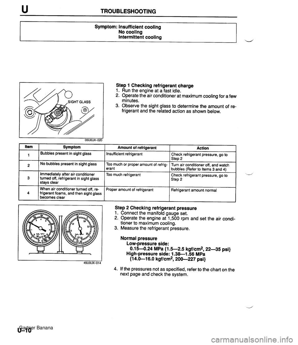
TROUBLESHOOTING I ltem 1 Symptom Symptom: lnsuff icient cooling No cooling Intermittent cooling Ill Bubbles present in sight glass u Immediately after air conditioner turned off, refrigerant in sight glass stavs clear I. When air conditioner turned off, re- frigerant foams, and then sight glass becomes clear No bubbles present in sight glass Step 1 Checking refrigerant charge 1. Run the engine at a fast idle. 2. Operate the air conditioner at maximum cooling for a few minutes. 3. Observe the sight glass to determine the amount of re- frigerant and the related action as shown below. Amount of refrigerant Action Insufficient refrigerant Too much or proper amount of refrig- erant Too much refrigerant Step 2 Checking refrigerant pressure 1. Connect the manifold gauge set. 2. Operate the engine at 1,500 rpm and set the air condi- tioner to maximum cooling. 3. Measure the refrigerant pressure. 1 Proper amount of refrigerant Normal pressure Low-pressure side: 0.1 5-4.24 MPa (1.5--2.5 kgf/cm2, 22--35 psi) High-pressure side: 1.38-1.56 MPa (1 4.0-1 6.0 kgf/cm2, 200-227 psi) Check refrigerant pressure, go to Step 2 Turn air conditioner off, and watch bubbles (Refer to Items 3 and 4) Check refrigerant pressure, go to Step 2 Refrigerant amount normal 4. If the pressures not as specified, refer to the chart on the next page and check the system. ,d Gartner Banana
Page 1073 of 1708
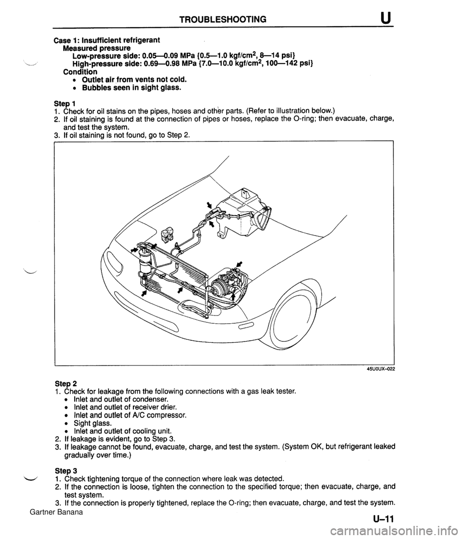
TROUBLESHOOTING Case 1: Insufficient refrigerant Measured pressure Low-pressure side: 0.05-4.09 MPa (0.5--1.0 kgf/cm2, 8-1 4 psi) u High-pressure side: 0.69-498 MPa (7.0-1 0.0 kgflcm2, 100-142 psi) Condition Outlet air from vents not cold. Bubbles seen in sight glass. Step 1 1. Check for oil stains on the pipes, hoses and other parts. (Refer to illustration below.) 2. If oil staining is found at the connection of pipes or hoses, replace the O-ring; then evacuate, charge, and test the svstem. 3. If oil staining k not found, go to Step 2. Step 2 1. Check for leakage from the following connections with a gas leak tester. lnlet and outlet of condenser. lnlet and outlet of receiver drier. lnlet and outlet of A.C compressor. Sight glass. lnkt and outlet of cooling unit. 2. If leakage is evident, go to Step 3. 3. If leakage cannot be found, evacuate, charge, and test the system. (System OK, but refrigerant leaked gradually over time.) Step 3 L-/ 1. Check tightening torque of the connection where leak was detected. 2. If the connection is loose, tighten the connection to the specified torque; then evacuate, charge, and test system. 3. If the connection is properly tightened, replace the O-ring; then evacuate, charge, and test the system. Gartner Banana
Page 1074 of 1708
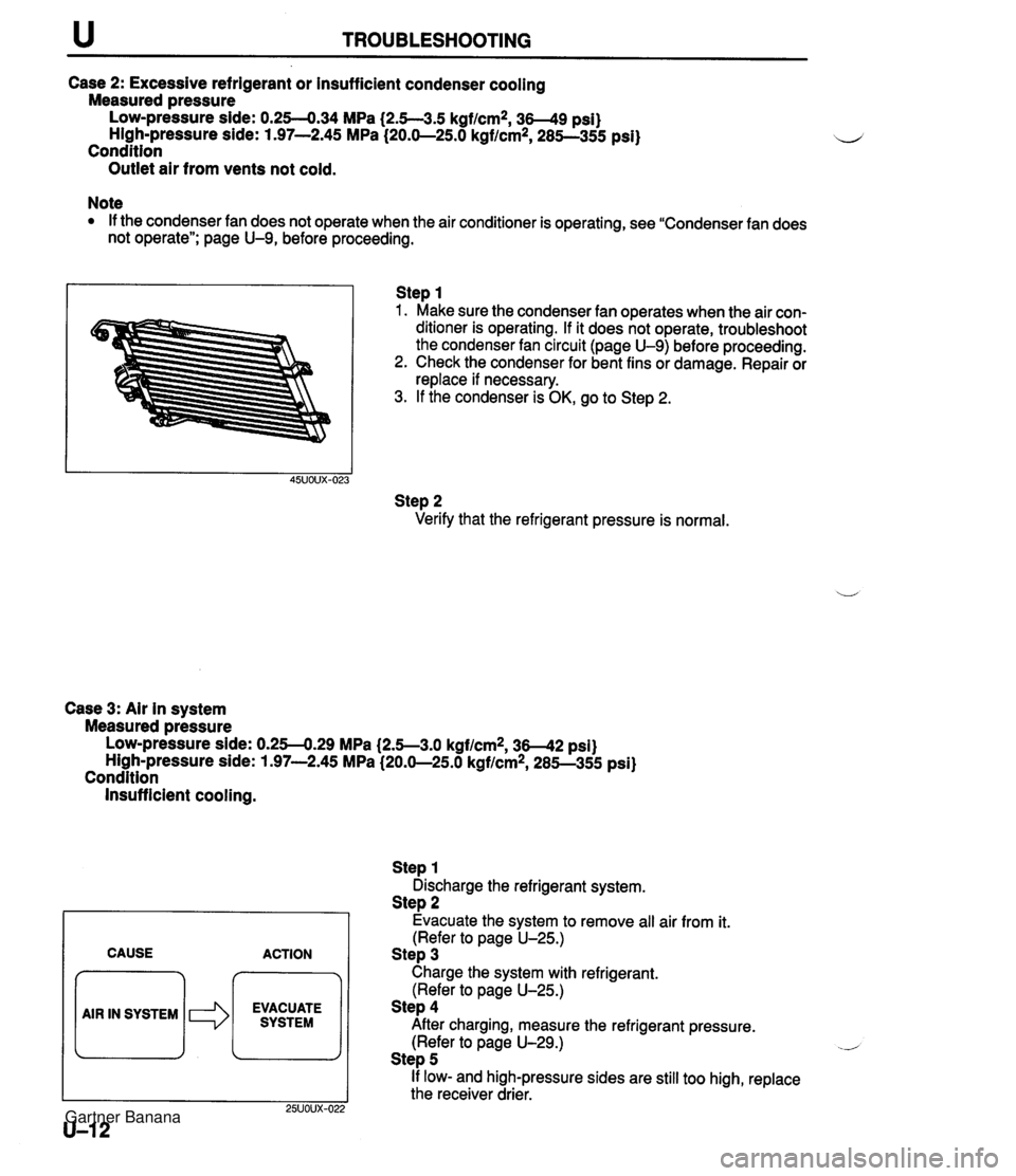
TROUBLESHOOTING Case 2: Excessive refrigerant or insufficient condenser cooling Measured pressure Low-pressure side: 0.254.34 MPa (2.5--3.5 kgf/cm2, 3-9 psi) High-pressure side: 1.97-2.45 MPa (20.0-25.0 kgflcm*, 285--355 psi) Condition Outlet air from vents not cold. Note If the condenser fan does not operate when the air conditioner is operating, see "Condenser fan does not operate"; page U-9, before proceeding. Step 1 1. Make sure the condenser fan operates when the air con- ditioner is operating. If it does not operate, troubleshoot the condenser fan circuit (page U-9) before proceeding. 2. Check the condenser for bent fins or damage. Repair or replace if necessary. 3. If the condenser is OK, go to Step 2. Step 2 Verify that the refrigerant pressure is normal. Case 3: Air in system Measured pressure Low-pressure side: 0.254.29 MPa (2.5--3.0 kgflcmz, 36-42 psi) High-pressure side: 1.97-2.45 MPa (20.0-25.0 kgf/cm2, 285--355 psi) Condition Insufficient cooling. CAUSE ACTION 7 EVACUATE SYSTEM Step 1 Discharge the refrigerant system. Step 2 Evacuate the system to remove all air from it. (Refer to page U-25.) Step 3 Charge the system with refrigerant. (Refer to page U-25.) Step 4 After charging, measure the refrigerant pressure. (Refer to page U-29.) .- Step 5 If low- and high-pressure sides are still too high, replace the receiver drier. Gartner Banana
Page 1075 of 1708
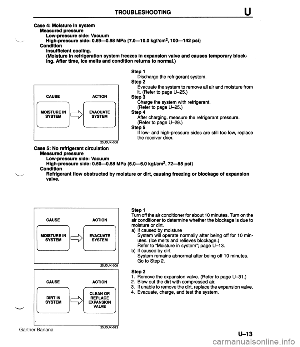
TROUBLESHOOTING Case 4: Moisture in system Measured pressure Low-pressure side: Vacuum High-pressure side: 0.69-4.98 MPa (7.O-lO.O kgf/cm2, 100-1 42 psi) Condition Insufficient cooling. (Moisture in refrigeration system freezes in expansion vaive and causes temporary block- ing. After time, ice melts and condition returns to normal.) CAUSE n MOISTURE IN I SYSTEM le ACTION EVACUATE SYSTEM Step 1 Discharge the refrigerant system. Step 2 Evacuate the system to remove all air and moisture from it. (Refer to page U-25.) Step 3 Charge the system with refrigerant. (Refer to page U-25.) Step 4 After charging, measure the refrigerant pressure. (Refer to page U-29.) Step 5 if low- and high-pressure sides are still too low, replace the receiver drier. Case 5: No refrigerant circulation Measured pressure Low-pressure side: Vacuum ~ighLpressure side: 0.50--0.58 MPa (5.0--6.0 kgf/cm2, 72-45 psi) Condition b Refrigerant flow obstructed by moisture or dirt, causing freezing or blockage of expansion valve. CAUSE ACTION MOISTURE IN CAUSE ACTION Step 1 Turn off the air conditioner for about 10 minutes. Turn on the air conditioner to determine whether the biockage is due to moisture or dirt. a) If caused by moisture System will operate normally after being off for 10 min- utes. (Ice melts and relieves blockage.) Refer to "Moisture in system"; page U-13. b) If caused by dirt System remains abnormal after being off 10 minutes. Go to Step 2. DIRT IN SYSTEM Step 2 1. Remove the expansion valve. (Refer to page U-31.) 2. Blow out the dirt with compressed air. 3. If unable to remove the dirt, replace the expansion valve. 4. Evacuate, charge, and test the system. CLEAN OR REPLACE EXPANSION VALVE Gartner Banana
Page 1085 of 1708
AIR CONDITIONER U AIR CONDITIONER PREPARATION i, SST I I c STRUCTURAL VIEW 00007-10331 Stopper, magnetic clutch 4992-02-020 Pressure plate remover For removal and installation of magnetic clutch For removal of pressure plate 1. Cooling unit 5. Condenser fan relay Removal I Installation ......... page U-30 Inspection ................... page U-37 Disassembly I Assembly ...... page U-31 6. AX: compressor 2. Condenser Removal I Installation ......... page U-38 Removal I Installation ......... page U-33 Disassembly I Assembly ...... page U-41 w 3. Receiver drier 7. Magnetic clutch Removal / Installation ......... page U-33 Disassembly / Assembly ...... page U-39 4. A/C relay Inspection ................... page U-37 Gartner Banana