Page 918 of 1708

LIGHTING SYSTEM T Symptom: Daytime running lights (DRL) do not illuminate. (Turn signals function normally.) DRL operate with engine running and following switches are off: Headlight switch Turn signal switch (Selected turn signal light flashes, other light remains illumi- nated) Hazard warning switch Parking brake switch (Parking brake released) Step 1 1. Position the vehicle on a flat surface and block the wheels to prevent vehicle movement. 2. Turn the ignition switch to ON. 3. Measure the voltage at the following terminal wires of the DRL control unit. 4. If correct, replace the DRL control unit. B+: Battery positive voltage Step 2 1. Disconnect the parking brake switch connector. 2. Check for continuity between the terminal of the switch and a body ground. Terminal J (L) u Connected to WIPER 20A fuse I(B) B (R) C (WIR) Parking brake lever Pulled one notch Continuity Yes Released Test condition Constant GND Parking brake switch Headlight switch No I 3. If not as specified, adjust or replace the parking brake switch. 4. If correct, repair wiring harness. (DRL control unit - Parking brake switch) Specification B+ Constant Parking brake released Headlight switch off Action Repair wiring harness (WIPER 20A - DRL control unit) Other B+ Other Repair wiring harness (DRL control unit - GND) Go to Step 2 Go to Step 3 Gartner Banana
Page 942 of 1708

CRUISE CONTROL SYSTEM B+: Battery Dositive voltage erminall Win color . . .. Action Connected to Cruise actuator Cruise actuator Test condition Main switch OFF Main switch ON Cruise A\actuator Specification Main switch OFF Main switch ON PCMT OV 9V Main switch OFF . Main switch ON Brake switch Go to Step 8 OV . 9V Ignition switch OFF lanition switch ON ParklNeutral switch Cruise control Main switch ON switch (Set switch and coast switch) Check main switch OV 9V - Brake pedal depressed Brake ~edal released Clutch switch Check main switch OV B+ Shift to "N" or "P" range Shift to other ranae Go to section K OV 9V Clutch pedal depressed Clutch pedal released Stoplight switch Go to Step 4 OV 5V Cruise control switch (Resume switch and accel switch) speed I While rotating rear tires I beMeenM,, sor Run I GO to Step 9 Go to section K OV B+ Brake pedal depressed Brake pedal released Cruise actuator I I I Battery 1 Constant I B+ I Repair wiring harness Go to Step 5 Main switch ON While turning resume switch after main switch ON B+ OV Main switch OFF Step 4 - Inspection of brake switch 1. Disconnect the brake switch connector. 2. Check for continuity between terminals of the switch. Go to Step 7 B+ OV OV GND 1 Constant Pedal position Go to Step 6 OV I Repair wiring harness Terminal A B 1 I Main switch ON 9V 45UOTX-19 Go to Step 8 3. If not as specified, replace the brake switch. 4. If the switch is OK, repair the wiring harness (fuse - brake switch - control unit). Pedal released Pedal depressed M: Continuity 0 0 Gartner Banana
Page 949 of 1708

CRUISE CONTROL SYSTEM B+: Battery positive voltage L rmlnall Wire color M Specification (RIL). . N Action Connected to (G) 0 CELERATOR DAL 9MUOTX-263 Test condition Cruise control switch (Set switch and coast switch) (w) P S T ACTUATOR CABLE Removal 1. Disconnect the actuator cable from the accelerator ped- al. 2. Remove the clamp at the inside of the firewall. (P) 3. Disconnect the actuator cable from the actuator. 4. Remove the clamps and the actuator cable. Main switch ON While turning set switch after main switch ON Check stoplight switch (Refer to page T-105) Stoplight switch Cruise control switch (Resume switch and accel switch) (WIG) (B) Installation Install in the reverse order of removal. Adjustment Remove the clamp and adjust the nut so that actuator cable free play is as shown when the cable is pressed lightly. B+ OV Brake pedal depressed I B+ Main switch ON While turning resume switch after main switch ON Actuator Cable play: 1 .O-3.0mm (0.04--0.12 in) Brake pedal released OV 9V Main switch OFF Main switch ON Vehicle speed sensor Battery GND Check cruise control switch (Refer to page T-106) OV B+ OV Check actuator (Refer to page T-107) Run out betweeno-5V B+ OV rotating rear tires Constant Constant d Check cruise control switch (Refer to page T-106) Check vehicle speed sensor (Refer to page T-106) Repair wire Re~air wire Gartner Banana
Page 1003 of 1708

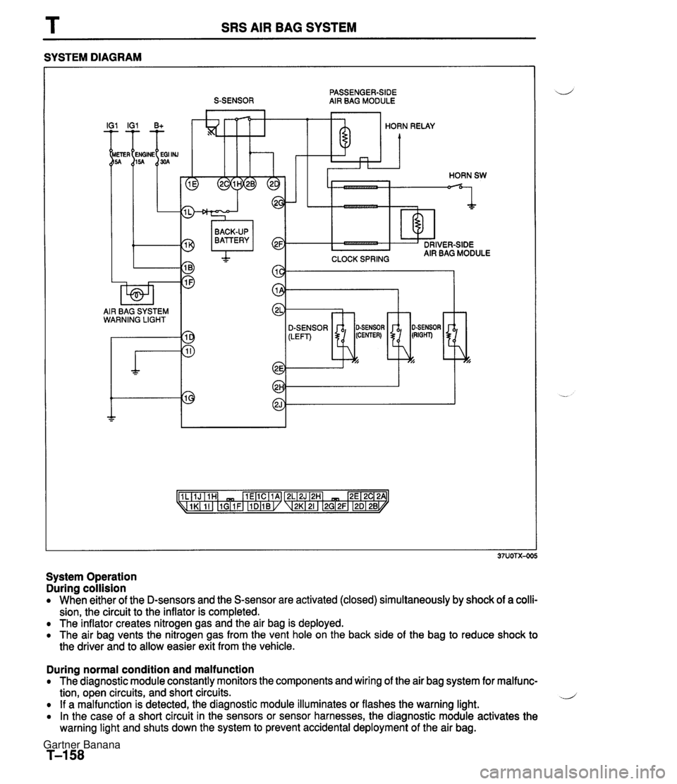
SRS AIR BAG SYSTEM SYSTEM DIAGRAM PASSENGER-SIDE S-SENSOR AIR BAG MODULE I IG1 B+ HORN RELAY CLOCK SPRING BACK-UP BATTERY I AIR BAG SYSTEM WARNING LIGHT SENSOR -7 System Operation During collision When either of the D-sensors and the S-sensor are activated (closed) simultaneously by shock of a colli- sion, the circuit to the inflator is completed. The inflator creates nitrogen gas and the air bag is deployed. The air bag vents the nitrogen gas from the vent hole on the back side of the bag to reduce shock to the driver and to allow easier exit from the vehicle. During normal condition and malfunction The diagnostic module constantly monitors the components and wiring of the air bag system for malfunc- tion, open circuits, and short circuits. .J If a malfunction is detected, the diagnostic module illuminates or flashes the warning light. In the case of a short circuit in the sensors or sensor harnesses, the diagnostic module activates the warning light and shuts down the system to prevent accidental deployment of the air bag. Gartner Banana
Page 1029 of 1708
T SRS AIR BAG SYSTEM I Flowchart No.16 I Symptom I Service Code 51 I Possible cause Blown internal fuse in diagnostic module (fault conditions no longer present) 0 Diagnostic module not replaced after service code 13 set and conditions corrected. Intermittent short in air bag deployment circuit. Remedy If repairs were made for a service code 13, replace the diagnostic module. If an intermittent short is sus- pected, inspect the wiring harnesses and connectors for damage. If they are not damaged, wiggle the harnesses and connectors to induce the intermittent short; service code 13 will be set when the fault is induced. Then follow the troubleshooting procedure for service code 13. 36EOTX-143 Gartner Banana
Page 1033 of 1708
Possible cause u 0 Burnt air bag warning light bulb Defective diagnostic module Defective wiring harness Step 1 Carry out "Before Servicing" procedure under GEN- ERAL PROCEDURES, page T-1 60. Air bag system warning light does not illuminate for 6 seconds Flowchart No.1 Step 2 1. Disconnect the diagnostic module connector. 2. Turn the ignition switch to ON. 3. Check the air bag warning light. I Llght condition I Action 1 Symptom 1 Illuminate I Replace diagnostic module (Refer to ~aae T-208) 1 -- I Not illuminate I GO to step 3 J Step 3 1. Remove the instrument cluster. 2. Check the air bag system warning light bulb. I Repair wiring harness (Diagnostic module--Instrument cluster) I Bulb Burnt Action Replace bulb .- Gartner Banana
Page 1034 of 1708
SRS AIR BAG SYSTEM T u Possible cause Poor connection of diagnostic module connector Defective diagnostic module Defective wiring harness Step 1 Carry out "Before Servicing" procedure under GEN- ERAL PROCEDURES, page T-1 60. Air bag warning light remains ON Flowchart No.2 Step 2 1. Verify that the diagnostic module connector is securely connected to the diagnostic module. 2. Verify that the shorting bar is in the fully retracted posi- tion. 3. If the connector and shorting bar are OK, go to step 3. Symptom Step 3 1. Disconnect the diagnostic module connector. 2. Remove the shorting bar from the diagnostic module connector. 3. Check the air bag warning light. Light condition I Action I Illuminate Repair wiring harness (Diagnostic modul~lnstrument duster) I Not illuminate 1 Replace diagnostic module (Refer to Dacie T-208) Gartner Banana
Page 1049 of 1708

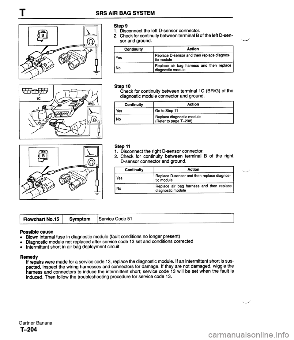
T SRS AIR BAG SYSTEM Step 9 1. Disconnect the left D-sensor connector. 2. Check for continuity between terminal B of the left D-sen- sor and ground. il I Continuity I Action I Step 10 Check for continuity between terminal 1 C (BRIG) of the diagnostic module connector and ground. I Continuity Action 1 Yes No I Yes I GO to step 11 Replace D-sensor and then replace diagnos- tic module Replace air bag harness and then replace diagnostic module Step 11 1. Disconnect the right D-sensor connector. 2. Check for continuity between terminal B of the right No D-sensor connectoiand ground. Replace diagnostic module (Refer to page T-208) Continuity Action Replace D-sensor and then replace diagnos- tic module Replace air bag harness and then replace I Flowchart No.15 I Symptom 1 Service Code 51 I Possible cause Blown internal fuse in diagnostic module (fault conditions no longer present) Diagnostic module not replaced after service code 13 set and conditions corrected Intermittent short in air bag deployment circuit Remedy If repairs were made for a service code 13, replace the diagnostic module. If an intermittent short is sus- pected, inspect the wiring harnesses and connectors for damage. If they are not damaged, wiggle the harness and connectors to induce the intermittent short; service code 13 will be set when the fault is induced. Then follow the troubleshooting procedure for service code 13. Gartner Banana