1994 JEEP CHEROKEE fuel pressure
[x] Cancel search: fuel pressurePage 898 of 1784
(28) Connect the heater hoses at the engine ther-
mostat housing and water pump.
(29) Install the fan assembly to the idler pulley.
(30) Install the radiator or radiator/condenser (if
equipped with A/C).
(31) Connect the service valves to the A/C com-
pressor ports, if equipped with A/C.
(32) Charge the air conditioner system.
(33) Connect radiator fan switch wire.
(34) Connect the radiator hoses and automatic
transmission fluid cooler pipes, if equipped.
(35) Install the fan shroud, electric cooling fan and
radiator/condenser (if equipped with A/C).
(36) Install upper radiator support.
(37) Connect the upper radiator hose and tighten
the clamp.
(38) Connect the lower radiator hose and tighten
the clamp.
(39) Fill the cooling system with reusable coolant
and/or new coolant.
(40) Align the hood to the scribe marks. Install the
hood.
(41) Connect the vacuum harness connector.
(a) Firmly push the connectors together ensuring
that the retaining tabs are engaged.
(b) Insert the vacuum connector assembly into
the retaining bracket on the intake manifold.
(42) Install the air cleaner assembly.
(43) Install the battery and connect the battery ca-
ble.
WARNING: USE EXTREME CAUTION WHEN THE
ENGINE IS OPERATING. DO NOT STAND IN A DI-
RECT LINE WITH THE FAN. DO NOT PUT YOUR
HANDS NEAR THE PULLEYS, BELTS OR FAN. DO
NOT WEAR LOOSE CLOTHING.
(44) Start the engine, inspect for leaks and correct
the fluid levels, as necessary.
ENGINE ASSEMBLYÐYJ VEHICLES
REMOVAL
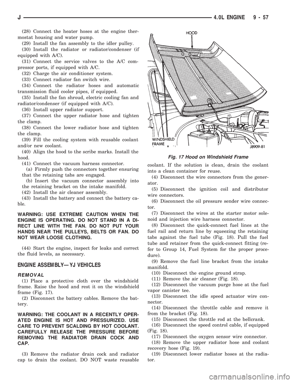
(1) Place a protective cloth over the windshield
frame. Raise the hood and rest it on the windshield
frame (Fig. 17).
(2) Disconnect the battery cables. Remove the bat-
tery.
WARNING: THE COOLANT IN A RECENTLY OPER-
ATED ENGINE IS HOT AND PRESSURIZED. USE
CARE TO PREVENT SCALDING BY HOT COOLANT.
CAREFULLY RELEASE THE PRESSURE BEFORE
REMOVING THE RADIATOR DRAIN COCK AND
CAP.
(3) Remove the radiator drain cock and radiator
cap to drain the coolant. DO NOT waste reusablecoolant. If the solution is clean, drain the coolant
into a clean container for reuse.
(4) Disconnect the wire connectors from the gener-
ator.
(5) Disconnect the ignition coil and distributor
wire connectors.
(6) Disconnect the oil pressure sender wire connec-
tor.
(7) Disconnect the wires at the starter motor sole-
noid and injection wire harness connector.
(8) Disconnect the quick-connect fuel lines at the
fuel rail and return line by squeezing the retaining
tabs against the fuel tube (Fig. 18). Pull the fuel
tube and retainer from the quick-connect fitting (re-
fer to Group 14, Fuel System for the proper proce-
dure).
(9) Remove the fuel line bracket from the intake
manifold.
(10) Disconnect the engine ground strap.
(11) Remove the air cleaner (Fig. 18).
(12) Disconnect the vacuum purge hose at the fuel
vapor canister tee.
(13) Disconnect the idle speed actuator wire con-
nector.
(14) Disconnect the throttle cable and remove it
from the bracket (Fig. 18).
(15) Disconnect the throttle rod at the bellcrank.
(16) Disconnect the speed control cable, if equipped
(Fig. 18).
(17) Disconnect the oxygen sensor wire connector.
(18) Remove the upper radiator hose and coolant
recovery hose (Fig. 19).
(19) Disconnect lower radiator hoses at the radia-
tor.
Fig. 17 Hood on Windshield Frame
J4.0L ENGINE 9 - 57
Page 903 of 1784
(9) Install the intake and engine exhaust mani-
folds (refer to Group 11, Exhaust System and Intake
Manifold for the proper procedures).
(10) Install the fuel lines and the vacuum advance
hose.
(11) If equipped, attach the power steering pump
and bracket.
(12) Install the push rods, rocker arms, pivots and
bridges in the order they were removed.
(13) Install the engine cylinder head cover.
(14) Attach the air conditioner compressor mount-
ing bracket to the engine cylinder head and block.
Tighten the bolts to 40 Nzm (30 ft. lbs.) torque.
(15) Attach the air conditioning compressor to the
bracket. Tighten the bolts to 27 Nzm (20 ft. lbs.)
torque.
CAUTION: The serpentine drive belt must be routed
correctly. Incorrect routing can cause the water
pump to turn in the opposite direction causing the
engine to overheat.
(16) Install the serpentine drive belt and correctly
tension the belt (refer to Group 7, Cooling System for
the proper procedure).
(17) Install the air cleaner and ducting.
(18) Install the engine cylinder head cover.
(19) Connect the hoses to the engine thermostat
housing and fill the cooling system to the specified
level (refer to Group 7, Cooling Systems for the
proper procedure).
(20) The automatic transmission throttle linkage
and cable must be adjusted after completing the en-
gine cylinder head installation (refer to Group 21,
Transmissions for the proper procedures).
(21) Install the temperature sending unit and con-
nect the wire connector.
(22) Connect the fuel pipe and vacuum advance
hose.
(23) Connect negative cable to battery.
(24) Connect the upper radiator hose and heater
hose at the engine thermostat housing.
(25) Fill the cooling system. Check for leaks.WARNING: USE EXTREME CAUTION WHEN THE
ENGINE IS OPERATING. DO NOT STAND IN DIRECT
LINE WITH THE FAN. DO NOT PUT HANDS NEAR
THE PULLEYS, BELTS OR FAN. DO NOT WEAR
LOOSE CLOTHING.
(26) Operate the engine with the radiator cap off.
Inspect for leaks and continue operating the engine
until the engine thermostat opens. Add coolant, if re-
quired.
VALVE SPRINGS AND OIL SEALS
This procedure can be done with the engine cylin-
der head installed on the block.
REMOVAL
Each valve spring is held in place by a retainer
and a set of conical valve locks. The locks can be re-
moved only by compressing the valve spring.
(1) Remove the engine cylinder head cover.
(2) Remove capscrews, bridge and pivot assemblies
and rocker arms for access to each valve spring to be
removed.
(3) Remove push rods. Retain the push rods,
bridges, pivots and rocker arms in the same order
and position as removed.
(4) Inspect the springs and retainer for cracks and
possible signs of weakening.
(5) Remove the spark plug(s) adjacent to the cylin-
der(s) below the valve springs to be removed.
(6) Install a 14 mm (1/2 inch) (thread size) air hose
adaptor in the spark plug hole. An adaptor can be
constructed by welding an air hose connection to the
body of a spark plug with the porcelain removed.
(7) Connect an air hose to the adapter and apply
air pressure slowly. Maintain at least 621 kPa (90
psi) of air pressure in the cylinder to hold the valves
against their seats. For vehicles equipped with an air
conditioner, use a flexible air adaptor when servicing
the No.1 cylinder.
(8) Tap the retainer or tip with a rawhide hammer
to loosen the lock from the retainer. Use Valve
Spring Compressor Tool MD-998772A to compress
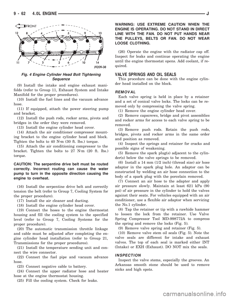
the spring and remove the locks (Fig. 5).
(9) Remove valve spring and retainer (Fig. 5).
(10) Remove valve stem oil seals (Fig. 5). Note the
valve seals are different for intake and exhaust
valves. The top of each seal is marked either INT
(Intake) or EXH (Exhaust). DO NOT mix the seals.
INSPECTION
Inspect the valve stems, especially the grooves. An
Arkansas smooth stone should be used to remove
nicks and high spots.
Fig. 4 Engine Cylinder Head Bolt Tightening
Sequence
9 - 62 4.0L ENGINEJ
Page 939 of 1784
INTAKE MANIFOLDÐ2.5L ENGINE
REMOVAL
(1) Disconnect the battery negative cable.
(2) Remove the air inlet hose from the throttle
body and air cleaner.
(3) Loosen the accessory drive belt tension and re-
move the belt from the power steering pump.
(4) Remove the power steering pump and brackets
from the water pump and intake manifold. Support
power steering pump and bracket with mechanics
wire attached to the radiator upper crossmember.
(5) Remove the fuel tank filler cap to relieve the
fuel tank pressure.
(6) Install the fuel tank filler cap.
(7) Disconnect fuel supply and return tube from
the fuel rail (refer to Group 14, Fuel System - Quick
Connect Fittings).
(8) Disconnect the accelerator cable from the throt-
tle body and the holddown bracket.
CAUTION: When disconnecting the cruise control
connector at the throttle body, DO NOT pry the con-
nector off with pliers or screwdriver. Use finger
pressure only. Prying the connector off could break
it.
(9) Disconnect the electrical connectors. Pull the
harnesses away from the manifold.
²The throttle position sensor.
²The idle speed control motor.
²The coolant temperature sensor at the thermostat.
²The manifold air temperature sensor at the intake
manifold.
²The fuel injectors.
²The oxygen sensor.
(10) Disconnect the crankcase ventilation (CCV)
vacuum hose and manifold absolute pressure (MAP)
sensor vacuum hose connector at the intake mani-
fold.
(11) Disconnect vacuum hose from vacuum port on
the intake manifold.
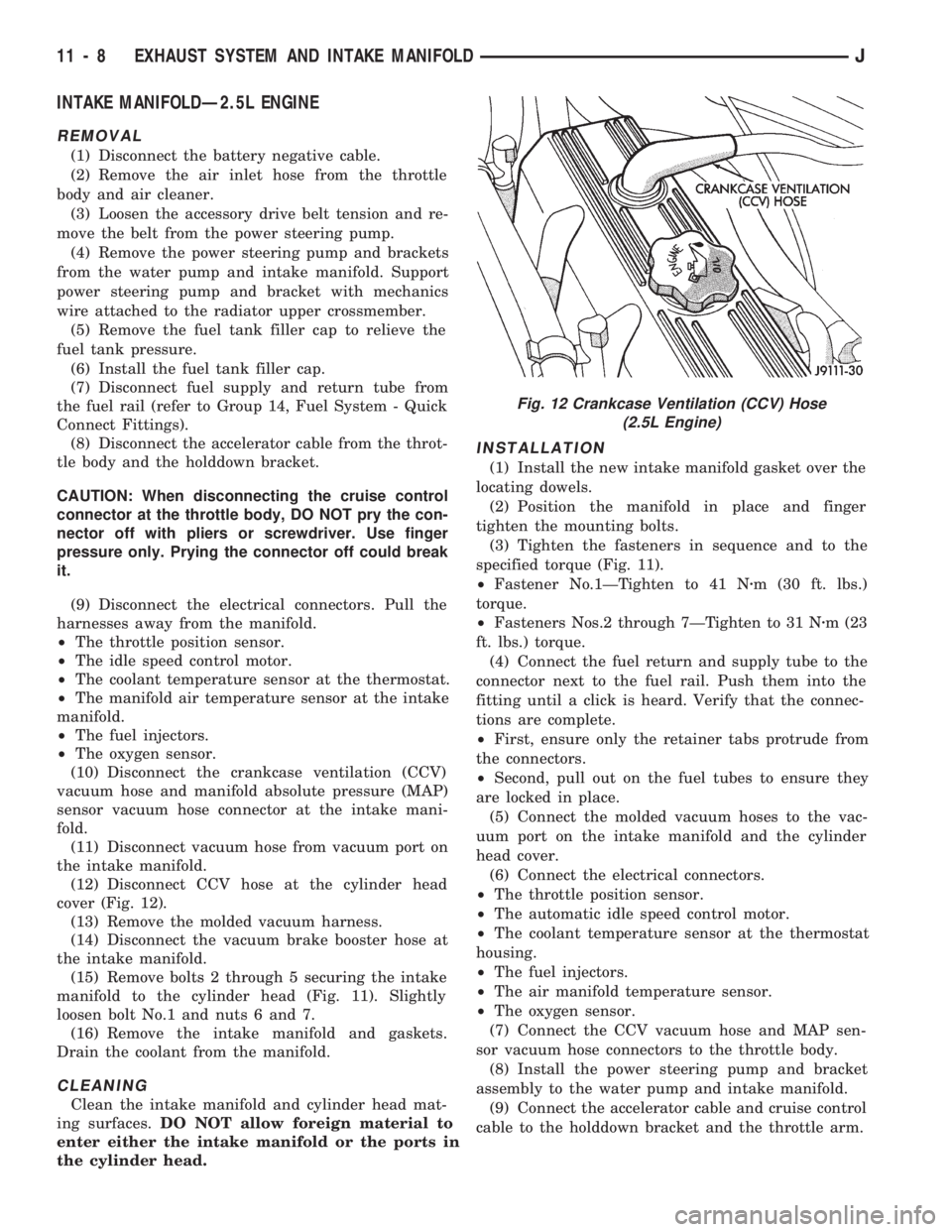
(12) Disconnect CCV hose at the cylinder head
cover (Fig. 12).
(13) Remove the molded vacuum harness.
(14) Disconnect the vacuum brake booster hose at
the intake manifold.
(15) Remove bolts 2 through 5 securing the intake
manifold to the cylinder head (Fig. 11). Slightly
loosen bolt No.1 and nuts 6 and 7.
(16) Remove the intake manifold and gaskets.
Drain the coolant from the manifold.
CLEANING
Clean the intake manifold and cylinder head mat-
ing surfaces.DO NOT allow foreign material to
enter either the intake manifold or the ports in
the cylinder head.
INSTALLATION
(1) Install the new intake manifold gasket over the
locating dowels.
(2) Position the manifold in place and finger
tighten the mounting bolts.
(3) Tighten the fasteners in sequence and to the
specified torque (Fig. 11).
²Fastener No.1ÐTighten to 41 Nzm (30 ft. lbs.)
torque.
²Fasteners Nos.2 through 7ÐTighten to 31 Nzm (23
ft. lbs.) torque.
(4) Connect the fuel return and supply tube to the
connector next to the fuel rail. Push them into the
fitting until a click is heard. Verify that the connec-
tions are complete.
²First, ensure only the retainer tabs protrude from
the connectors.
²Second, pull out on the fuel tubes to ensure they
are locked in place.
(5) Connect the molded vacuum hoses to the vac-
uum port on the intake manifold and the cylinder
head cover.
(6) Connect the electrical connectors.
²The throttle position sensor.
²The automatic idle speed control motor.
²The coolant temperature sensor at the thermostat
housing.
²The fuel injectors.
²The air manifold temperature sensor.
²The oxygen sensor.
(7) Connect the CCV vacuum hose and MAP sen-
sor vacuum hose connectors to the throttle body.
(8) Install the power steering pump and bracket
assembly to the water pump and intake manifold.
(9) Connect the accelerator cable and cruise control
cable to the holddown bracket and the throttle arm.
Fig. 12 Crankcase Ventilation (CCV) Hose
(2.5L Engine)
11 - 8 EXHAUST SYSTEM AND INTAKE MANIFOLDJ
Page 940 of 1784
CAUTION: Ensure that the accessory drive belt is
routed correctly. Failure to do so can cause the wa-
ter pump to turn in the opposite direction resulting
in engine overheating. Refer to Group 7, Cooling
System for the proper procedure.
(10) Tension the accessory drive belt. Refer to
Group 7, Cooling System for the proper procedure.
(11) Connect the air inlet hose to the throttle body
and the air cleaner.
(12) Connect the battery negative cable.
(13) Start the engine and check for leaks.
INTAKE MANIFOLDÐ4.0L ENGINE
The intake and engine exhaust manifolds on the
4.0L engine must be removed and installed together.
The two manifolds use a common gasket at the cyl-
inder head.
REMOVAL
(1) Disconnect the battery negative cable.
(2) Remove air cleaner inlet hose from throttle
plate assembly.
(3) Remove the air cleaner assembly.
(4) Remove the throttle cable, cruise control cable (if
equipped) and the transmission line pressure cable.
(5) Disconnect all electrical connectors on the in-
take manifold.
(6) Disconnect and remove the fuel supply and re-
turn lines from the fuel rail assembly (refer to Group
14, Fuel System).
(7) Loosen the accessory drive belt (refer to Group
7, Cooling System). Loosen the tensioner.
(8) Remove the power steering pump and bracket
from the intake manifold and set aside.
(9) Remove the fuel rail and injectors (refer to
Group 14, Fuel System).
(10) Raise the vehicle.
(11) Disconnect the exhaust pipe from the engine
exhaust manifold. Discard the seal.
(12) Lower the vehicle.
(13) Remove the intake manifold and engine ex-
haust manifold.
CLEANING
Clean the mating surfaces of the cylinder head and
the manifold if the original manifold is to be installed.
If the manifold is being replaced, ensure all the fit-
ting, etc. are transferred to the replacement manifold.
INSTALLATION
(1) Install a new exhaust/intake manifold gasket
over the alignment dowels on the cylinder head.
(2) Position the engine exhaust manifold to the
cylinder head. Install fastener No.3 and finger
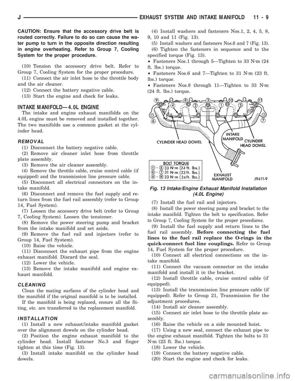
tighten at this time (Fig. 13).
(3) Install intake manifold on the cylinder head
dowels.(4) Install washers and fasteners Nos.1, 2, 4, 5, 8,
9, 10 and 11 (Fig. 13).
(5) Install washers and fasteners Nos.6 and 7 (Fig. 13).
(6) Tighten the fasteners in sequence and to the
specified torque (Fig. 13).
²Fasteners Nos.1 through 5ÐTighten to 33 Nzm (24
ft. lbs.) torque.
²Fasteners Nos.6 and 7ÐTighten to 31 Nzm (23 ft.
lbs.) torque.
²Fasteners Nos.8 through 11ÐTighten to 33 Nzm
(24 ft. lbs.) torque.
(7) Install the fuel rail and injectors.
(8) Install the power steering pump and bracket to the
intake manifold. Tighten the belt to specification. Refer
to Group 7, Cooling System for the proper procedures.
(9) Install the fuel supply and return lines to the
fuel rail assembly.Before connecting the fuel
lines to the fuel rail replace the O-rings in the
quick-connect fuel line couplings.Refer to Group
14, Fuel System for the proper procedure.
(10) Connect all electrical connections on the in-
take manifold.
(11) Connect the vacuum connector on the intake
manifold and install it in the bracket.
(12) Install throttle cable, cruise control cable (if
equipped).
(13) Install the transmission line pressure cable (if
equipped). Refer to Group 21, Transmission for the
adjustment procedures.
(14) Install air cleaner assembly.
(15) Connect air inlet hose to the throttle plate as-
sembly.
(16) Raise the vehicle on a side mounted hoist.
(17) Using a new seal, connect the exhaust pipe to
the engine exhaust manifold. Tighten the bolts to 31
Nzm (23 ft. lbs.) torque.
(18) Lower the vehicle.
(19) Connect the battery negative cable.
(20) Start the engine and check for leaks.
Fig. 13 Intake/Engine Exhaust Manifold Installation
(4.0L Engine)
JEXHAUST SYSTEM AND INTAKE MANIFOLD 11 - 9
Page 962 of 1784
FUEL SYSTEM
CONTENTS
page page
ACCELERATOR PEDAL AND THROTTLE CABLE... 16
FUEL DELIVERY SYSTEM................. 2
FUEL TANKS........................... 12
GENERAL INFORMATION.................. 1
MULTI-PORT FUEL INJECTION (MFI)ÐCOMPO-
NENT DESCRIPTION/SYSTEM OPERATION . 17MULTI-PORT FUEL INJECTION (MFI)Ð
COMPONENT REMOVAL/INSTALLATION . . . 54
MULTI-PORT FUEL INJECTION (MFI)Ð
GENERAL DIAGNOSIS.................. 32
SPECIFICATIONS....................... 62
GENERAL INFORMATION
Throughout this group, references are made to par-
ticular vehicle models by alphabetical designation or
by the particular vehicle nameplate. A chart showing
a breakdown of the alphabetical designations is in-
cluded in the Introduction section at the beginning of
this manual.
TheFuel Systemconsists of: the fuel tank, an
electric (fuel tank mounted) fuel pump and a fuel fil-
ter. It also consists of fuel tubes/lines/hoses, vacuum
hoses, throttle body and fuel injectors.
TheFuel Delivery Systemconsists of: the electric
fuel pump, fuel filter, fuel tubes/lines/hoses, fuel rail,
fuel injectors and fuel pressure regulator.
AFuel Return Systemis used on all vehicles.
The system consists of: the fuel tubes/lines/hoses that
route fuel back to the fuel tank.
TheFuel Tank Assemblyconsists of: the fuel
tank, filler tube, fuel gauge sending unit/electric fuel
pump module, a pressure relief/rollover valve and a
pressure-vacuum filler cap.
Also to be considered part of the fuel system is the
Evaporation Control System.This is designed to
reduce the emission of fuel vapors into the atmo-
sphere. The description and function of the Evapora-
tive Control System is found in Group 25, Emission
Control Systems.
FUEL USAGE STATEMENT
Your vehicle was designed to meet all emission reg-
ulations and provide excellent fuel economy using
high quality unleaded gasoline. Only use unleaded
gasolines having a minimum posted octane of 87.
If your vehicle develops occasional light spark
knock (ping) at low engine speeds, this is not harm-
ful. However,continued heavy knock at high
speeds can cause damage and should be re-
ported to your dealer immediately.Engine dam-age as a result of heavy knock operation may not be
covered by the new vehicle warranty.
In addition to using unleaded gasoline with the
proper octane rating,those that contain deter-
gents, corrosion and stability additives are rec-
ommended.Using gasolines that have these
additives will help improve fuel economy, reduce
emissions and maintain vehicle performance. Gener-
ally, premium unleaded gasolines contain more addi-
tive than regular unleaded gasolines.
Poor quality gasolinecan cause problems such
as hard starting, stalling and stumble. If you experi-
ence these problems, use another brand of gasoline
before considering service for the vehicle.
GASOLINE/OXYGENATE BLENDS
Some fuel suppliers blend unleaded gasoline with
materials that contain oxygen such as alcohol, MTBE
and ETBE. The type and amount of oxygenate used
in the blend is important. The following are generally
used in gasoline blends:
ETHANOL
Ethanol (Ethyl or Grain Alcohol) properly blended,
is used as a mixture of 10 percent ethanol and 90
percent gasoline.Gasoline with ethanol may be
used in your vehicle.
METHANOL
CAUTION: DO NOT USE GASOLINES CONTAINING
METHANOL.Use of methanol/gasoline blends may re-
sult in starting and driveability problems. In addition,
damage may be done to critical fuel system compo-
nents.
Methanol (Methyl or Wood Alcohol) is used in a va-
riety of concentrations blended with unleaded gaso-
JFUEL SYSTEM 14 - 1
Page 963 of 1784
line. You may encounter fuels containing 3 percent
or more methanol along with other alcohols called co-
solvents.
Problems that are the result of using methanol/gas-
oline blends are not the responsibility of Chrysler
Corporation. They may not be covered by the vehicle
warranty.
MTBE/ETBE
Gasoline and MTBE (Methyl Tertiary Butyl Ether)
blends are a mixture of unleaded gasoline and up to
15 percent MTBE. Gasoline and ETBE (Ethyl Ter-
tiary Butyl Ether) are blends of gasoline and up to
17 percent ETBE. Gasoline blended with MTBE or
ETBE may be used in your vehicle.CLEAN AIR GASOLINE
Many gasolines are now being blended that con-
tribute to cleaner air, especially in those areas of the
country where air pollution levels are high. These
new blends provide a cleaner burning fuel and some
are referred to asReformulated Gasoline.
In areas of the country where carbon monoxide lev-
els are high, gasolines are being treated with oxy-
genated materials such as MTBE, ETBE and
ethanol.
Chrysler Corporation supports these efforts toward
cleaner air and recommends that you use these gas-
olines as they become available.
FUEL DELIVERY SYSTEM
INDEX
page page
Fuel Filter............................... 8
Fuel Pressure Leak Down Test............... 7
Fuel Pressure Release Procedure............. 5
Fuel Pump Capacity Test................... 7
Fuel Pump Electrical Control................. 5Fuel Pump Module........................ 2
Fuel System Pressure Test.................. 5
Fuel Tubes/Lines/Hoses and Clamps........... 9
Quick-Connect Fittings..................... 9
FUEL PUMP MODULE
The fuel pump module is installed in the top of the
fuel tank. The fuel pump module contains the follow-
ing components:
²Electric fuel pump
²Fuel pump reservoir
²In-tank fuel filter
²Fuel gauge sending unit
²Fuel supply and return tube connections
The fuel pump used on all vehicles is a gear/rotor
type pump. It is driven by a permanent magnet 12
volt electric motor that is immersed in the fuel tank.
The electrical pump is integral with the fuel sender
unit. The pump/sender assembly is installed inside
the fuel tank.
The fuel pump has a check valve at the outlet end
that consists of a ball held against a seat by force ap-
plied from a spring. When the pump is operating,
fuel pressure overcomes spring pressure and forces
the ball off its seat, allowing fuel to flow. When the
pump is not operating, spring pressure forces the ball
back against the seat preventing fuel backflow
through the pump.
Fuel system pressure is maintained at approxi-
mately 214 kPa (31 psi). This is when the pump is
operating and vacuum is supplied to the fuel pres-
sure regulator. If vacuum is not supplied to the pres-
sure regulator, fuel pressure will be approximately
55-69 kPa (8-10 psi) higher. This may be due to a
broken or clogged vacuum line. When the fuel pumpis not operating, system fuel pressure of 131-269 kPa
(19-39 psi) is maintained. This is done by the fuel
pump outlet check valve and the vacuum assisted
fuel pressure regulator.
REMOVALÐXJ MODELS
The fuel pump/gauge sender unit assembly can be
removed from the fuel tank without removing the
tank from the vehicle.
WARNING: THE FUEL SYSTEM IS UNDER A CON-
STANT PRESSURE (EVEN WITH THE ENGINE OFF).
BEFORE SERVICING THE FUEL PUMP MODULE,
THE FUEL SYSTEM PRESSURE MUST BE RE-
LEASED. REFER TO THE FUEL PRESSURE RE-
LEASE PROCEDURE IN THIS GROUP.
WARNING: EXTINGUISH ALL TOBACCO SMOKING
PRODUCTS BEFORE SERVICING THE FUEL SYS-
TEM. KEEP OPEN FLAME AWAY FROM FUEL SYS-
TEM COMPONENTS.
(1) Remove fuel filler cap. Perform the Fuel Pres-
sure Release Procedure as outlined in this group.
(2) Disconnect negative battery cable.
(3) Using an approved portable gasoline siphon/
storage tank, drain fuel tank until fuel level is below
one quarter (1/4) full.
(4) Raise and support vehicle.
14 - 2 FUEL SYSTEMJ
Page 965 of 1784
(3) Using a brass punch and a hammer, install
lock ring. Carefully tap lock ring clockwise until it
seats against stop on fuel tank.
(4) Connect fuel supply and return hoses to fittings
on fuel pump module. Tighten hose clamps.
(5) Connect fuel pump module electrical harness
connector to main harness connector.
(6) Lower vehicle.
(7) Fill fuel tank. Install fuel tank cap.
(8) Connect negative battery cable.
(9) Start vehicle and inspect for leaks.
REMOVALÐYJ MODELS
The fuel tank must be removed to remove the fuel
pump module.
WARNING: THE FUEL SYSTEM IS UNDER A CON-
STANT PRESSURE (EVEN WITH THE ENGINE OFF).
BEFORE SERVICING THE FUEL PUMP MODULE,
THE FUEL SYSTEM PRESSURE MUST BE RE-
LEASED. REFER TO THE FUEL PRESSURE RE-
LEASE PROCEDURE IN THIS GROUP.
WARNING: EXTINGUISH ALL TOBACCO SMOKING
PRODUCTS BEFORE SERVICING THE FUEL SYS-
TEM. KEEP OPEN FLAME AWAY FROM FUEL SYS-
TEM COMPONENTS.
(1) Remove negative battery cable.
(2) Remove fuel filler cap. Perform the Fuel Pres-
sure Release Procedure as outlined in this group.
(3) Remove fuel tank. Refer to Fuel Tank Remov-
alÐYJ Models.
(4) Remove fuel pump module assembly.
(5) Remove mounting screws. Lift assembly and
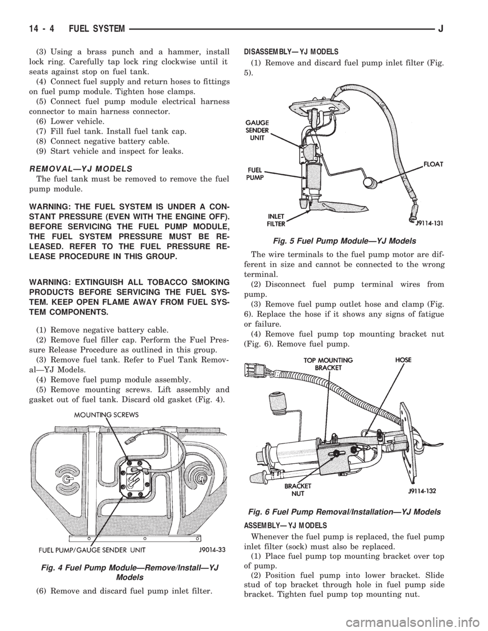
gasket out of fuel tank. Discard old gasket (Fig. 4).
(6) Remove and discard fuel pump inlet filter.DISASSEMBLYÐYJ MODELS
(1) Remove and discard fuel pump inlet filter (Fig.
5).
The wire terminals to the fuel pump motor are dif-
ferent in size and cannot be connected to the wrong
terminal.
(2) Disconnect fuel pump terminal wires from
pump.
(3) Remove fuel pump outlet hose and clamp (Fig.
6). Replace the hose if it shows any signs of fatigue
or failure.
(4) Remove fuel pump top mounting bracket nut
(Fig. 6). Remove fuel pump.
ASSEMBLYÐYJ MODELS
Whenever the fuel pump is replaced, the fuel pump
inlet filter (sock) must also be replaced.
(1) Place fuel pump top mounting bracket over top
of pump.
(2) Position fuel pump into lower bracket. Slide
stud of top bracket through hole in fuel pump side
bracket. Tighten fuel pump top mounting nut.
Fig. 4 Fuel Pump ModuleÐRemove/InstallÐYJ
Models
Fig. 5 Fuel Pump ModuleÐYJ Models
Fig. 6 Fuel Pump Removal/InstallationÐYJ Models
14 - 4 FUEL SYSTEMJ
Page 966 of 1784
(3) Install new fuel pump outlet hose. Secure with
new clamps.
(4) Connect wire terminals to motor.
(5) Install new fuel pump inlet filter.
INSTALLATIONÐYJ MODELS
(1) Install a new fuel pump inlet filter.
(2) Install fuel pump module assembly with a new
gasket between the assembly and tank. Tighten
mounting screws to 2 Nzm (18 in. lbs.) torque.
(3) Install fuel tank. Refer to Fuel Tank Installa-
tionÐYJ Models.
(4) Fill fuel tank. Install fuel tank cap.
(5) Install negative battery cable.
(6) Start vehicle and check for leaks.
FUEL PUMP ELECTRICAL CONTROL
For an electrical operational description of the fuel
pump, refer to the MFI SystemÐComponent Descrip-
tion/System Operation section of this group. See Au-
tomatic Shut Down (ASD) RelayÐPCM Output.
For the 1994 model year, the ballast resistor and
ballast resistor bypass relay are no longer used to
control the fuel pump circuit.
FUEL PRESSURE RELEASE PROCEDURE
WARNING: THE FUEL SYSTEM IS UNDER CON-
STANT FUEL PRESSURE (EVEN WITH THE ENGINE
OFF) OF APPROXIMATELY 131-269 KPA (19-39
PSI). THIS PRESSURE MUST BE RELEASED BE-
FORE SERVICING ANY FUEL SUPPLY OR FUEL RE-
TURN SYSTEM COMPONENT.
(1) Disconnect negative battery cable.
(2) Remove fuel tank filler neck cap to release fuel
tank pressure.
WARNING: DO NOT ALLOW FUEL TO SPILL ONTO
THE ENGINE INTAKE OR EXHAUST MANIFOLDS.
PLACE SHOP TOWELS UNDER AND AROUND THE
PRESSURE PORT TO ABSORB FUEL WHEN THE
PRESSURE IS RELEASED FROM THE FUEL RAIL.
WARNING: WEAR PROPER EYE PROTECTION
WHEN RELEASING FUEL SYSTEM PRESSURE.
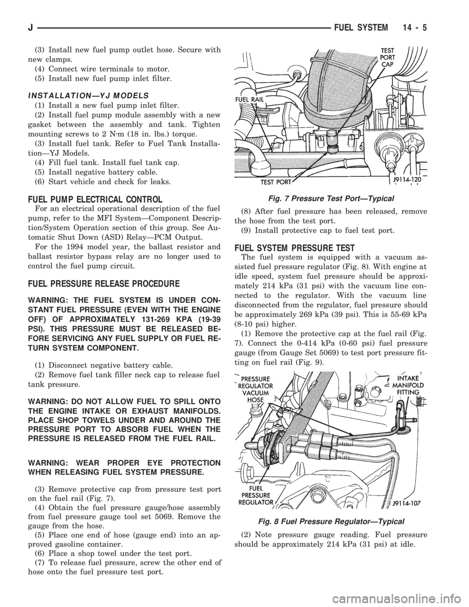
(3) Remove protective cap from pressure test port
on the fuel rail (Fig. 7).
(4) Obtain the fuel pressure gauge/hose assembly
from fuel pressure gauge tool set 5069. Remove the
gauge from the hose.
(5) Place one end of hose (gauge end) into an ap-
proved gasoline container.
(6) Place a shop towel under the test port.
(7) To release fuel pressure, screw the other end of
hose onto the fuel pressure test port.(8) After fuel pressure has been released, remove
the hose from the test port.
(9) Install protective cap to fuel test port.
FUEL SYSTEM PRESSURE TEST
The fuel system is equipped with a vacuum as-
sisted fuel pressure regulator (Fig. 8). With engine at
idle speed, system fuel pressure should be approxi-
mately 214 kPa (31 psi) with the vacuum line con-
nected to the regulator. With the vacuum line
disconnected from the regulator, fuel pressure should
be approximately 269 kPa (39 psi). This is 55-69 kPa
(8-10 psi) higher.
(1) Remove the protective cap at the fuel rail (Fig.
7). Connect the 0-414 kPa (0-60 psi) fuel pressure
gauge (from Gauge Set 5069) to test port pressure fit-
ting on fuel rail (Fig. 9).
(2) Note pressure gauge reading. Fuel pressure
should be approximately 214 kPa (31 psi) at idle.
Fig. 7 Pressure Test PortÐTypical
Fig. 8 Fuel Pressure RegulatorÐTypical
JFUEL SYSTEM 14 - 5