1994 JEEP CHEROKEE change time
[x] Cancel search: change timePage 1014 of 1784
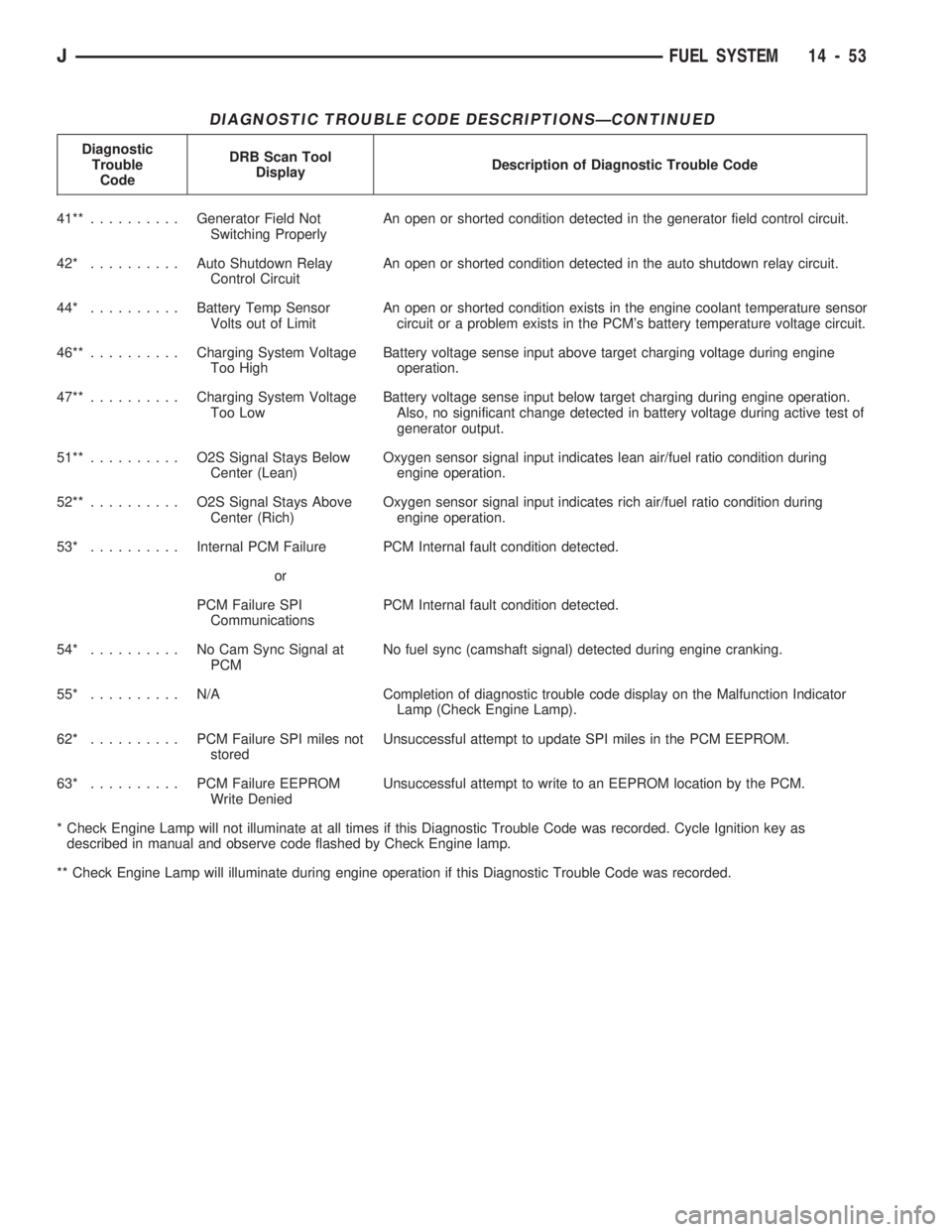
DIAGNOSTIC TROUBLE CODE DESCRIPTIONSÐCONTINUED
Diagnostic
Trouble
CodeDRB Scan Tool
DisplayDescription of Diagnostic Trouble Code
41**..........Generator Field Not
Switching ProperlyAn open or shorted condition detected in the generator field control circuit.
42* ..........Auto Shutdown Relay
Control CircuitAn open or shorted condition detected in the auto shutdown relay circuit.
44* ..........Battery Temp Sensor
Volts out of LimitAn open or shorted condition exists in the engine coolant temperature sensor
circuit or a problem exists in the PCM's battery temperature voltage circuit.
46**..........Charging System Voltage
Too HighBattery voltage sense input above target charging voltage during engine
operation.
47**..........Charging System Voltage
Too LowBattery voltage sense input below target charging during engine operation.
Also, no significant change detected in battery voltage during active test of
generator output.
51**.......... O2SSignal Stays Below
Center (Lean)Oxygen sensor signal input indicates lean air/fuel ratio condition during
engine operation.
52**.......... O2SSignal Stays Above
Center (Rich)Oxygen sensor signal input indicates rich air/fuel ratio condition during
engine operation.
53* ..........Internal PCM Failure PCM Internal fault condition detected.
or
PCM Failure SPI
CommunicationsPCM Internal fault condition detected.
54* .......... NoCamSync Signal at
PCMNo fuel sync (camshaft signal) detected during engine cranking.
55* .......... N/ACompletion of diagnostic trouble code display on the Malfunction Indicator
Lamp (Check Engine Lamp).
62* .......... PCMFailure SPI miles not
storedUnsuccessful attempt to update SPI miles in the PCM EEPROM.
63* .......... PCMFailure EEPROM
Write DeniedUnsuccessful attempt to write to an EEPROM location by the PCM.
* Check Engine Lamp will not illuminate at all times if this Diagnostic Trouble Code was recorded. Cycle Ignition key as
described in manual and observe code flashed by Check Engine lamp.
** Check Engine Lamp will illuminate during engine operation if this Diagnostic Trouble Code was recorded.
JFUEL SYSTEM 14 - 53
Page 1025 of 1784
shaft must be able to change operating angles when
going over various road surfaces. This is done
through universal joints, which permit the propeller
shaft to operate at different angles. The slip joints (or
yokes) permit contraction or expansion (Fig. 1,2).
Tubular propeller shafts are balanced by the man-
ufacturer with weights spot welded to the tube.
The propeller shaft is designed and built with the
yoke lugs in line with each other which is called
phasing. This design produces the smoothest running
condition, an out of phase shaft can cause a vibra-
tion.
Before undercoating a vehicle, the propeller
shaft and the U-joints should be covered. This
will prevent the undercoating from causing an
unbalanced condition and vibration.
CAUTION: Use exact replacement hardware for at-
taching the propeller shafts. The specified torque
must always be applied when tightening the fasten-
ers.
UNIVERSAL JOINTS
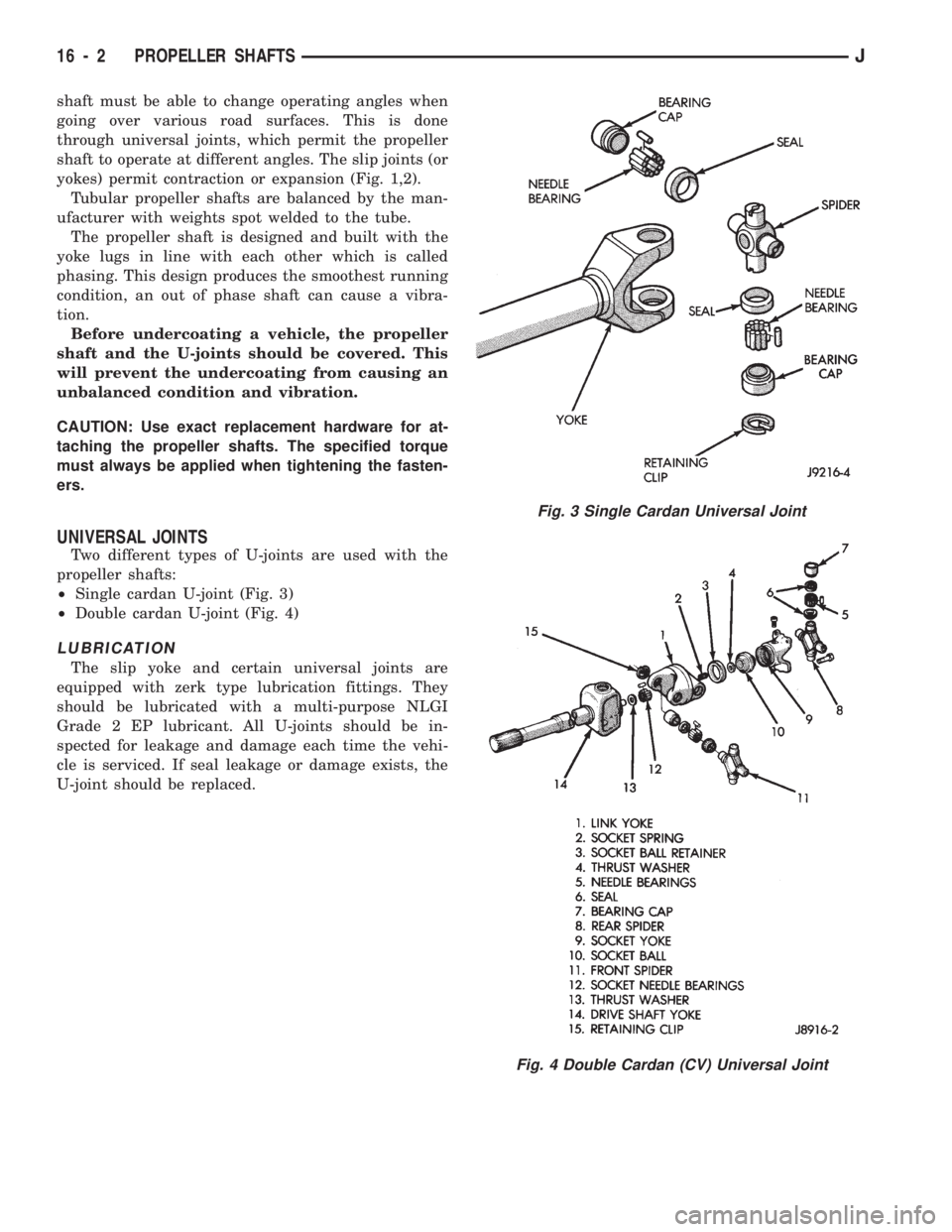
Two different types of U-joints are used with the
propeller shafts:
²Single cardan U-joint (Fig. 3)
²Double cardan U-joint (Fig. 4)
LUBRICATION
The slip yoke and certain universal joints are
equipped with zerk type lubrication fittings. They
should be lubricated with a multi-purpose NLGI
Grade 2 EP lubricant. All U-joints should be in-
spected for leakage and damage each time the vehi-
cle is serviced. If seal leakage or damage exists, the
U-joint should be replaced.
Fig. 3 Single Cardan Universal Joint
Fig. 4 Double Cardan (CV) Universal Joint
16 - 2 PROPELLER SHAFTSJ
Page 1217 of 1784
condenser. The auxiliary cooler is a serviceable com-
ponent and can be repaired if necessary.
The main and auxiliary coolers should be thor-
oughly reverse flushed if a transmission failure
contaminates the fluid. Reverse flushing the cooler
and lines will prevent sludge and particles from
flowing back into the transmission after repair.
The same flushing procedure is used for main and
auxiliary coolers. Pressure equipment is preferred for
reverse flushing. However, reverse flushing can be
performed using hand operated equipment as de-
scribed in the following procedure.
REVERSE FLUSHING PROCEDURE
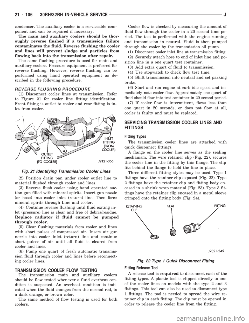
(1) Disconnect cooler lines at transmission. Refer
to Figure 21 for cooler line fitting identification.
Front fitting is outlet to cooler and rear fitting is in-
let from cooler.
(2) Position drain pan under cooler outlet line to
material flushed through cooler and lines.
(3) Reverse flush cooler using hand operated suc-
tion gun filled with mineral spirits. Insert gun nozzle
(or hose) into cooler inlet (return) line. Then force
mineral spirits through Line and cooler.
(4) Continue reverse flushing until fluid exiting in-
let (pressure) line is clear and free of debris/residue.
Replace radiator if fluid cannot be pumped
through cooler.
(5) Clear flushing materials from cooler and lines
with short pulses of compressed air. Insert air gun
nozzle into cooler inlet (return) line and continue
short pulses of air until all fluid is cleared from
cooler and lines.
(6) Pump one quart of fresh automatic transmis-
sion fluid through cooler and lines before reconnect-
ing cooler lines.
TRANSMISSION COOLER FLOW TESTING
The transmission main and auxiliary coolers
should be flow tested whenever a fluid overheat con-
dition is suspected. An overheat condition is indi-
cated when the fluid changes from the normal red, to
a dark orange, or brown color.
The same method of flow testing is used for both
coolers.Cooler flow is checked by measuring the amount of
fluid flow through the cooler in a 20 second time pe-
riod. The test is performed with the engine running
and transmission in neutral. Fluid is then pumped
through the cooler by the transmission oil pump.
(1) Disconnect cooler inlet line at transmission fitting.
(2) Securely attach hose to end of inlet line and po-
sition line in a one quart test container.
(3) Add extra quart of fluid to transmission.
(4) Use stopwatch to check flow test time.
(5) Shift transmission into neutral and set parking
brake.
(6) Start and run engine at curb idle speed and im-
mediately note cooler flow. Approximately one quart of
fluid should flow into test container in 20 second period.
(7) If cooler flow is intermittent, flows less than
one quart in 20 seconds, or does not flow at all,
cooler is faulty and must be replaced.
SERVICING TRANSMISSION COOLER LINES AND
FITTINGS
Fitting Types
The transmission cooler lines are attached with
quick disconnect fittings.
A flange on the cooler line serves as the sealing
mechanism. The wire retainer clip (Fig. 22), secures
the cooler line in the fitting by this flange. The clip
fits behind the flange to hold the line in place.
Three different fitting styles may be used. Type 1
fittings have the retainer clip exposed (Fig. 22). Type
2 fittings have the retainer clip and fitting body en-
cased in a shrink wrap material (Fig. 23). Type 3 fit-
tings have the retainer clip encased in a metal sleeve
crimped onto the fitting body (Fig. 24).
Fitting Release Tool
A release tool isrequiredto disconnect each of the
fitting types. A plastic tool is clipped directly to one
of the cooler lines on models with the type 2 and 3
fittings. This tool can also be used to disconnect type
1 fittings. The tool is needed to spread the wire re-
tainer clip in each fitting. The clip must be opened in
order to release the cooler line from the fitting.
Fig. 21 Identifying Transmission Cooler Lines
Fig. 22 Type 1 Quick Disconnect Fitting
21 - 106 30RH/32RH IN-VEHICLE SERVICEJ
Page 1452 of 1784
Radial runout of more than 1.5 mm (.060 inch)
measured at the center line of the tread may cause
the vehicle to shake.
Lateral runout of more than 2.0 mm (.080 inch)
measured near the shoulder of the tire may cause the
vehicle to shake.
Sometimes radial runout can be reduced. Relocate
the wheel and tire assembly on the mounting studs
(See Method 1). If this does not reduce runout to an
acceptable level, the tire can be rotated on the wheel.
(See Method 2).
METHOD 1 (RELOCATE WHEEL ON HUB)
Check accuracy of the wheel mounting surface; ad-
just wheel bearings.
Drive vehicle a short distance to eliminate tire flat
spotting from a parked position.
Make sure all wheel nuts are properly torqued.
Relocate wheel on the mounting, two studs over
from the original position.
Re-tighten wheel nuts until all are properly
torqued, to eliminate brake distortion.
Check radial runout. If still excessive, mark tire
sidewall, wheel, and stud at point of maximum
runout and proceed to Method 2.
METHOD 2 (RELOCATE TIRE ON WHEEL)
Rotating tire on wheel is particularly effective
when there is runout in both tire and wheel.Remove tire from wheel and re-mount wheel on
hub in former position.
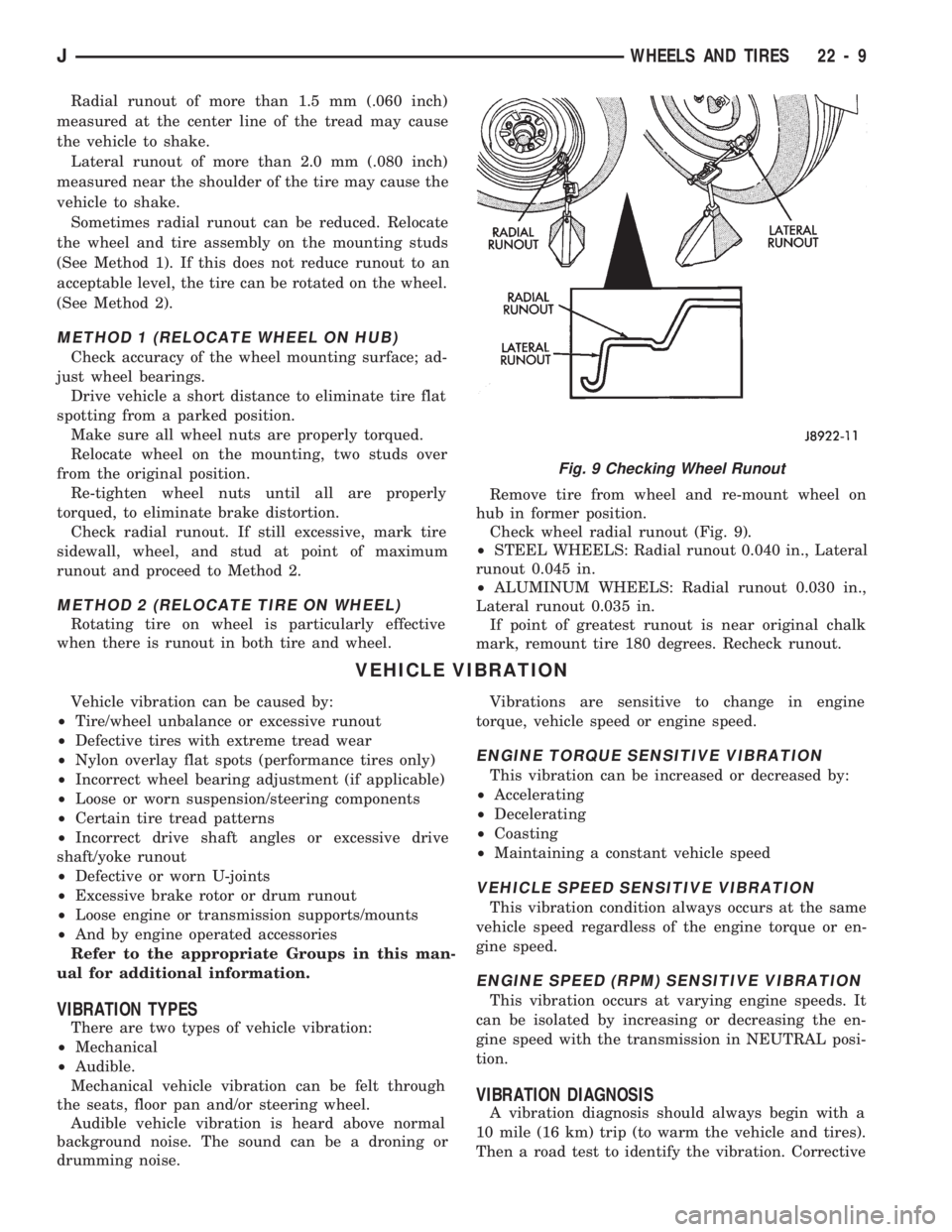
Check wheel radial runout (Fig. 9).
²STEEL WHEELS: Radial runout 0.040 in., Lateral
runout 0.045 in.
²ALUMINUM WHEELS: Radial runout 0.030 in.,
Lateral runout 0.035 in.
If point of greatest runout is near original chalk
mark, remount tire 180 degrees. Recheck runout.
VEHICLE VIBRATION
Vehicle vibration can be caused by:
²Tire/wheel unbalance or excessive runout
²Defective tires with extreme tread wear
²Nylon overlay flat spots (performance tires only)
²Incorrect wheel bearing adjustment (if applicable)
²Loose or worn suspension/steering components
²Certain tire tread patterns
²Incorrect drive shaft angles or excessive drive
shaft/yoke runout
²Defective or worn U-joints
²Excessive brake rotor or drum runout
²Loose engine or transmission supports/mounts
²And by engine operated accessories
Refer to the appropriate Groups in this man-
ual for additional information.
VIBRATION TYPES
There are two types of vehicle vibration:
²Mechanical
²Audible.
Mechanical vehicle vibration can be felt through
the seats, floor pan and/or steering wheel.
Audible vehicle vibration is heard above normal
background noise. The sound can be a droning or
drumming noise.Vibrations are sensitive to change in engine
torque, vehicle speed or engine speed.
ENGINE TORQUE SENSITIVE VIBRATION
This vibration can be increased or decreased by:
²Accelerating
²Decelerating
²Coasting
²Maintaining a constant vehicle speed
VEHICLE SPEED SENSITIVE VIBRATION
This vibration condition always occurs at the same
vehicle speed regardless of the engine torque or en-
gine speed.
ENGINE SPEED (RPM) SENSITIVE VIBRATION
This vibration occurs at varying engine speeds. It
can be isolated by increasing or decreasing the en-
gine speed with the transmission in NEUTRAL posi-
tion.
VIBRATION DIAGNOSIS
A vibration diagnosis should always begin with a
10 mile (16 km) trip (to warm the vehicle and tires).
Then a road test to identify the vibration. Corrective
Fig. 9 Checking Wheel Runout
JWHEELS AND TIRES 22 - 9
Page 1730 of 1784
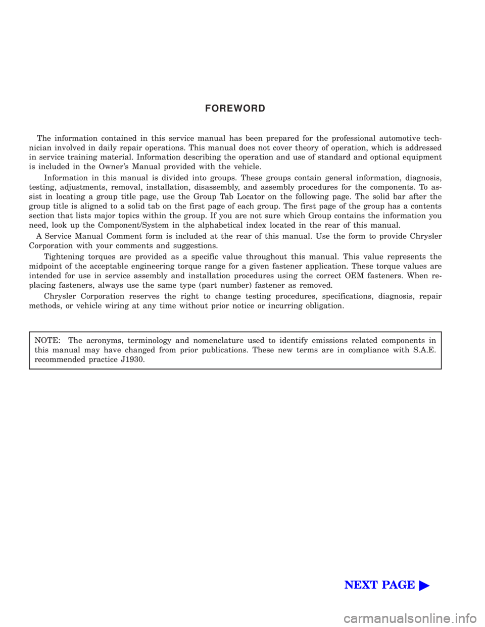
FOREWORD
The information contained in this service manual has been prepared for the professional automotive tech-
nician involved in daily repair operations. This manual does not cover theory of operation, which is addressed
in service training material. Information describing the operation and use of standard and optional equipment
is included in the Owner 's Manual provided with the vehicle.
Information in this manual is divided into groups. These groups contain general information, diagnosis,
testing, adjustments, removal, installation, disassembly, and assembly procedures for the components. To as-
sist in locating a group title page, use the Group Tab Locator on the following page. The solid bar after the
group title is aligned to a solid tab on the first page of each group. The first page of the group has a contents
section that lists major topics within the group. If you are not sure which Group contains the information you
need, look up the Component/System in the alphabetical index located in the rear of this manual.
A Service Manual Comment form is included at the rear of this manual. Use the form to provide Chrysler
Corporation with your comments and suggestions.
Tightening torques are provided as a specific value throughout this manual. This value represents the
midpoint of the acceptable engineering torque range for a given fastener application. These torque values are
intended for use in service assembly and installation procedures using the correct OEM fasteners. When re-
placing fasteners, always use the same type (part number) fastener as removed.
Chrysler Corporation reserves the right to change testing procedures, specifications, diagnosis, repair
methods, or vehicle wiring at any time without prior notice or incurring obligation.
NOTE: The acronyms, terminology and nomenclature used to identify emissions related components in
this manual may have changed from prior publications. These new terms are in compliance with S.A.E.
recommended practice J1930.
NEXT PAGE©
Page 1734 of 1784
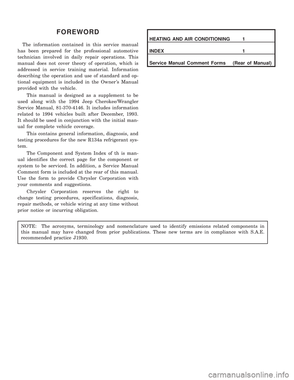
FOREWORD
The information contained in this service manual
has been prepared for the professional automotive
technician involved in daily repair operations. This
manual does not cover theory of operation, which is
addressed in service training material. Information
describing the operation and use of standard and op-
tional equipment is included in the Owner 's Manual
provided with the vehicle.
This manual is designed as a supplement to be
used along with the 1994 Jeep Cherokee/Wrangler
Service Manual, 81-370-4146. It includes information
related to 1994 vehicles built after December, 1993.
It should be used in conjunction with the initial man-
ual for complete vehicle coverage.
This contains general information, diagnosis, and
testing procedures for the new R134a refrigerant sys-
tem.
The Component and System Index of th is man-
ual identifies the correct page for the component or
system to be serviced. In addition, a Service Manual
Comment form is included at the rear of this manual.
Use the form to provide Chrysler Corporation with
your comments and suggestions.
Chrysler Corporation reserves the right to
change testing procedures, specifications, diagnosis,
repair methods, or vehicle wiring at any time without
prior notice or incurring obligation.
HEATING AND AIR CONDITIONING 1
INDEX 1
Service Manual Comment Forms (Rear of Manual)
NOTE: The acronyms, terminology and nomenclature used to identify emissions related components in
this manual may have changed from prior publications. These new terms are in compliance with S.A.E.
recommended practice J1930.
Page 1748 of 1784
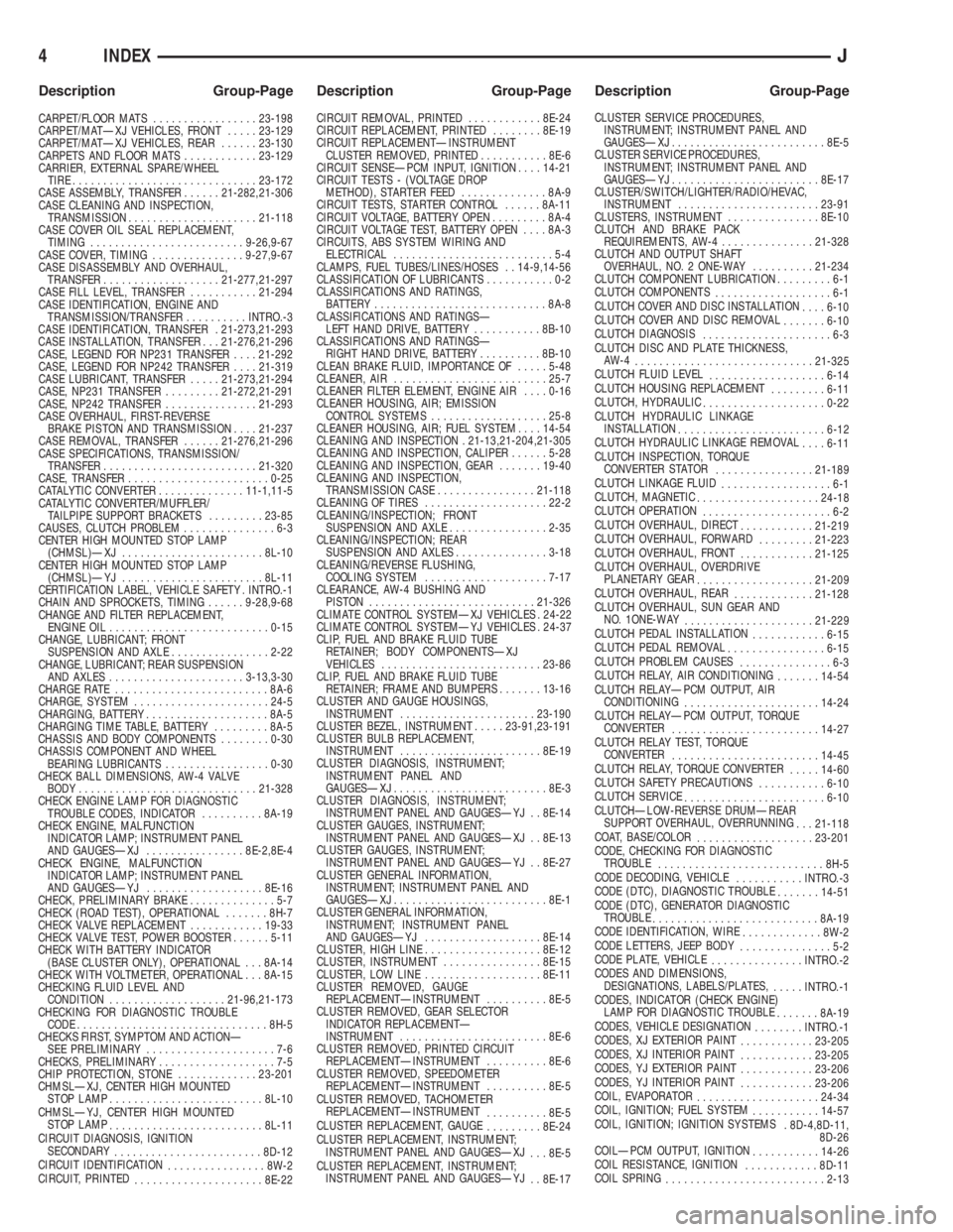
CARPET/FLOOR MATS.................23-198
CARPET/MATÐXJ VEHICLES, FRONT.....23-129
CARPET/MATÐXJ VEHICLES, REAR......23-130
CARPETS AND FLOOR MATS............23-129
CARRIER, EXTERNAL SPARE/WHEEL
TIRE..............................23-172
CASE ASSEMBLY, TRANSFER......21-282,21-306
CASE CLEANING AND INSPECTION,
TRANSMISSION.....................21-118
CASE COVER OIL SEAL REPLACEMENT,
TIMING.........................9-26,9-67
CASE COVER, TIMING...............9-27,9-67
CASE DISASSEMBLY AND OVERHAUL,
TRANSFER...................21-277,21-297
CASE FILL LEVEL, TRANSFER...........21-294
CASE IDENTIFICATION, ENGINE AND
TRANSMISSION/TRANSFER..........INTRO.-3
CASE IDENTIFICATION, TRANSFER . 21-273,21-293
CASE INSTALLATION, TRANSFER . . . 21-276,21-296
CASE, LEGEND FOR NP231 TRANSFER....21-292
CASE, LEGEND FOR NP242 TRANSFER....21-319
CASE LUBRICANT, TRANSFER.....21-273,21-294
CASE, NP231 TRANSFER.........21-272,21-291
CASE, NP242 TRANSFER...............21-293
CASE OVERHAUL, FIRST-REVERSE
BRAKE PISTON AND TRANSMISSION....21-237
CASE REMOVAL, TRANSFER......21-276,21-296
CASE SPECIFICATIONS, TRANSMISSION/
TRANSFER.........................21-320
CASE, TRANSFER.......................0-25
CATALYTIC CONVERTER..............11-1,11-5
CATALYTIC CONVERTER/MUFFLER/
TAILPIPE SUPPORT BRACKETS.........23-85
CAUSES, CLUTCH PROBLEM...............6-3
CENTER HIGH MOUNTED STOP LAMP
(CHMSL)ÐXJ.......................8L-10
CENTER HIGH MOUNTED STOP LAMP
(CHMSL)ÐYJ.......................8L-11
CERTIFICATION LABEL, VEHICLE SAFETY . INTRO.-1
CHAIN AND SPROCKETS, TIMING......9-28,9-68
CHANGE AND FILTER REPLACEMENT,
ENGINE OIL..........................0-15
CHANGE, LUBRICANT; FRONT
SUSPENSION AND AXLE................2-22
CHANGE, LUBRICANT; REAR SUSPENSION
AND AXLES......................3-13,3-30
CHARGE RATE.........................8A-6
CHARGE, SYSTEM......................24-5
CHARGING, BATTERY....................8A-5
CHARGING TIME TABLE, BATTERY.........8A-5
CHASSIS AND BODY COMPONENTS........0-30
CHASSIS COMPONENT AND WHEEL
BEARING LUBRICANTS.................0-30
CHECK BALL DIMENSIONS, AW-4 VALVE
BODY.............................21-328
CHECK ENGINE LAMP FOR DIAGNOSTIC
TROUBLE CODES, INDICATOR..........8A-19
CHECK ENGINE, MALFUNCTION
INDICATOR LAMP; INSTRUMENT PANEL
AND GAUGESÐXJ................8E-2,8E-4
CHECK ENGINE, MALFUNCTION
INDICATOR LAMP; INSTRUMENT PANEL
AND GAUGESÐYJ...................8E-16
CHECK, PRELIMINARY BRAKE..............5-7
CHECK (ROAD TEST), OPERATIONAL.......8H-7
CHECK VALVE REPLACEMENT............19-33
CHECK VALVE TEST, POWER BOOSTER......5-11
CHECK WITH BATTERY INDICATOR
(BASE CLUSTER ONLY), OPERATIONAL . . . 8A-14
CHECK WITH VOLTMETER, OPERATIONAL . . . 8A-15
CHECKING FLUID LEVEL AND
CONDITION...................21-96,21-173
CHECKING FOR DIAGNOSTIC TROUBLE
CODE...............................8H-5
CHECKS FIRST, SYMPTOM AND ACTIONÐ
SEE PRELIMINARY.....................7-6
CHECKS, PRELIMINARY...................7-5
CHIP PROTECTION, STONE.............23-201
CHMSLÐXJ, CENTER HIGH MOUNTED
STOP LAMP.........................8L-10
CHMSLÐYJ, CENTER HIGH MOUNTED
STOP LAMP
.........................8L-11
CIRCUIT DIAGNOSIS, IGNITION
SECONDARY
........................8D-12
CIRCUIT IDENTIFICATION
................8W-2
CIRCUIT, PRINTED
.....................8E-22CIRCUIT REMOVAL, PRINTED............8E-24
CIRCUIT REPLACEMENT, PRINTED........8E-19
CIRCUIT REPLACEMENTÐINSTRUMENT
CLUSTER REMOVED, PRINTED...........8E-6
CIRCUIT SENSEÐPCM INPUT, IGNITION....14-21
CIRCUIT TESTS - (VOLTAGE DROP
METHOD), STARTER FEED..............8A-9
CIRCUIT TESTS, STARTER CONTROL......8A-11
CIRCUIT VOLTAGE, BATTERY OPEN.........8A-4
CIRCUIT VOLTAGE TEST, BATTERY OPEN....8A-3
CIRCUITS, ABS SYSTEM WIRING AND
ELECTRICAL..........................5-4
CLAMPS, FUEL TUBES/LINES/HOSES . . 14-9,14-56
CLASSIFICATION OF LUBRICANTS...........0-2
CLASSIFICATIONS AND RATINGS,
BATTERY............................8A-8
CLASSIFICATIONS AND RATINGSÐ
LEFT HAND DRIVE, BATTERY...........8B-10
CLASSIFICATIONS AND RATINGSÐ
RIGHT HAND DRIVE, BATTERY..........8B-10
CLEAN BRAKE FLUID, IMPORTANCE OF.....5-48
CLEANER, AIR.........................25-7
CLEANER FILTER ELEMENT, ENGINE AIR....0-16
CLEANER HOUSING, AIR; EMISSION
CONTROL SYSTEMS...................25-8
CLEANER HOUSING, AIR; FUEL SYSTEM....14-54
CLEANING AND INSPECTION . 21-13,21-204,21-305
CLEANING AND INSPECTION, CALIPER......5-28
CLEANING AND INSPECTION, GEAR.......19-40
CLEANING AND INSPECTION,
TRANSMISSION CASE................21-118
CLEANING OF TIRES....................22-2
CLEANING/INSPECTION; FRONT
SUSPENSION AND AXLE................2-35
CLEANING/INSPECTION; REAR
SUSPENSION AND AXLES...............3-18
CLEANING/REVERSE FLUSHING,
COOLING SYSTEM....................7-17
CLEARANCE, AW-4 BUSHING AND
PISTON...........................21-326
CLIMATE CONTROL SYSTEMÐXJ VEHICLES . 24-22
CLIMATE CONTROL SYSTEMÐYJ VEHICLES . 24-37
CLIP, FUEL AND BRAKE FLUID TUBE
RETAINER; BODY COMPONENTSÐXJ
VEHICLES..........................23-86
CLIP, FUEL AND BRAKE FLUID TUBE
RETAINER; FRAME AND BUMPERS.......13-16
CLUSTER AND GAUGE HOUSINGS,
INSTRUMENT......................23-190
CLUSTER BEZEL, INSTRUMENT.....23-91,23-191
CLUSTER BULB REPLACEMENT,
INSTRUMENT.......................8E-19
CLUSTER DIAGNOSIS, INSTRUMENT;
INSTRUMENT PANEL AND
GAUGESÐXJ.........................8E-3
CLUSTER DIAGNOSIS, INSTRUMENT;
INSTRUMENT PANEL AND GAUGESÐYJ . . 8E-14
CLUSTER GAUGES, INSTRUMENT;
INSTRUMENT PANEL AND GAUGESÐXJ . . 8E-13
CLUSTER GAUGES, INSTRUMENT;
INSTRUMENT PANEL AND GAUGESÐYJ . . 8E-27
CLUSTER GENERAL INFORMATION,
INSTRUMENT; INSTRUMENT PANEL AND
GAUGESÐXJ.........................8E-1
CLUSTER GENERAL INFORMATION,
INSTRUMENT; INSTRUMENT PANEL
AND GAUGESÐYJ...................8E-14
CLUSTER, HIGH LINE...................8E-12
CLUSTER, INSTRUMENT................8E-15
CLUSTER, LOW LINE...................8E-11
CLUSTER REMOVED, GAUGE
REPLACEMENTÐINSTRUMENT..........8E-5
CLUSTER REMOVED, GEAR SELECTOR
INDICATOR REPLACEMENTÐ
INSTRUMENT........................8E-6
CLUSTER REMOVED, PRINTED CIRCUIT
REPLACEMENTÐINSTRUMENT..........8E-6
CLUSTER REMOVED, SPEEDOMETER
REPLACEMENTÐINSTRUMENT..........8E-5
CLUSTER REMOVED, TACHOMETER
REPLACEMENTÐINSTRUMENT
..........8E-5
CLUSTER REPLACEMENT, GAUGE
.........8E-24
CLUSTER REPLACEMENT, INSTRUMENT;
INSTRUMENT PANEL AND GAUGESÐXJ
. . . 8E-5
CLUSTER REPLACEMENT, INSTRUMENT;
INSTRUMENT PANEL AND GAUGESÐYJ
. . 8E-17CLUSTER SERVICE PROCEDURES,
INSTRUMENT; INSTRUMENT PANEL AND
GAUGESÐXJ.........................8E-5
CLUSTER SERVICE PROCEDURES,
INSTRUMENT; INSTRUMENT PANEL AND
GAUGESÐYJ........................8E-17
CLUSTER/SWITCH/LIGHTER/RADIO/HEVAC,
INSTRUMENT.......................23-91
CLUSTERS, INSTRUMENT...............8E-10
CLUTCH AND BRAKE PACK
REQUIREMENTS, AW-4...............21-328
CLUTCH AND OUTPUT SHAFT
OVERHAUL, NO. 2 ONE-WAY..........21-234
CLUTCH COMPONENT LUBRICATION.........6-1
CLUTCH COMPONENTS
...................6-1
CLUTCH COVER AND DISC INSTALLATION
....6-10
CLUTCH COVER AND DISC REMOVAL
.......6-10
CLUTCH DIAGNOSIS
.....................6-3
CLUTCH DISC AND PLATE THICKNESS,
AW-4
.............................21-325
CLUTCH FLUID LEVEL
...................6-14
CLUTCH HOUSING REPLACEMENT
.........6-11
CLUTCH, HYDRAULIC
....................0-22
CLUTCH HYDRAULIC LINKAGE
INSTALLATION
........................6-12
CLUTCH HYDRAULIC LINKAGE REMOVAL
....6-11
CLUTCH INSPECTION, TORQUE
CONVERTER STATOR
................21-189
CLUTCH LINKAGE FLUID
..................6-1
CLUTCH, MAGNETIC
....................24-18
CLUTCH OPERATION
.....................6-2
CLUTCH OVERHAUL, DIRECT
............21-219
CLUTCH OVERHAUL, FORWARD
.........21-223
CLUTCH OVERHAUL, FRONT
............21-125
CLUTCH OVERHAUL, OVERDRIVE
PLANETARY GEAR
...................21-209
CLUTCH OVERHAUL, REAR
.............21-128
CLUTCH OVERHAUL, SUN GEAR AND
NO. 1ONE-WAY
.....................21-229
CLUTCH PEDAL INSTALLATION
............6-15
CLUTCH PEDAL REMOVAL
................6-15
CLUTCH PROBLEM CAUSES
...............6-3
CLUTCH RELAY, AIR CONDITIONING
.......14-54
CLUTCH RELAYÐPCM OUTPUT, AIR
CONDITIONING
......................14-24
CLUTCH RELAYÐPCM OUTPUT, TORQUE
CONVERTER
........................14-27
CLUTCH RELAY TEST, TORQUE
CONVERTER
........................14-45
CLUTCH RELAY, TORQUE CONVERTER
.....14-60
CLUTCH SAFETY PRECAUTIONS
...........6-10
CLUTCH SERVICE
.......................6-10
CLUTCHÐLOW-REVERSE DRUMÐREAR
SUPPORT OVERHAUL, OVERRUNNING
. . . 21-118
COAT, BASE/COLOR
...................23-201
CODE, CHECKING FOR DIAGNOSTIC
TROUBLE
...........................8H-5
CODE DECODING, VEHICLE
...........INTRO.-3
CODE (DTC), DIAGNOSTIC TROUBLE
.......14-51
CODE (DTC), GENERATOR DIAGNOSTIC
TROUBLE
...........................8A-19
CODE IDENTIFICATION, WIRE
.............8W-2
CODE LETTERS, JEEP BODY
...............5-2
CODE PLATE, VEHICLE
...............INTRO.-2
CODES AND DIMENSIONS,
DESIGNATIONS, LABELS/PLATES,
.....INTRO.-1
CODES, INDICATOR (CHECK ENGINE)
LAMP FOR DIAGNOSTIC TROUBLE
.......8A-19
CODES, VEHICLE DESIGNATION
........INTRO.-1
CODES, XJ EXTERIOR PAINT
............23-205
CODES, XJ INTERIOR PAINT
............23-205
CODES, YJ EXTERIOR PAINT
............23-206
CODES, YJ INTERIOR PAINT
............23-206
COIL, EVAPORATOR
....................24-34
COIL, IGNITION; FUEL SYSTEM
...........14-57
COIL, IGNITION; IGNITION SYSTEMS
. 8D-4,8D-11,
8D-26
COILÐPCM OUTPUT, IGNITION
...........14-26
COIL RESISTANCE, IGNITION
............8D-11
COIL SPRING
..........................2-13
4 INDEXJ
Description Group-Page Description Group-Page Description Group-Page
Page 1757 of 1784
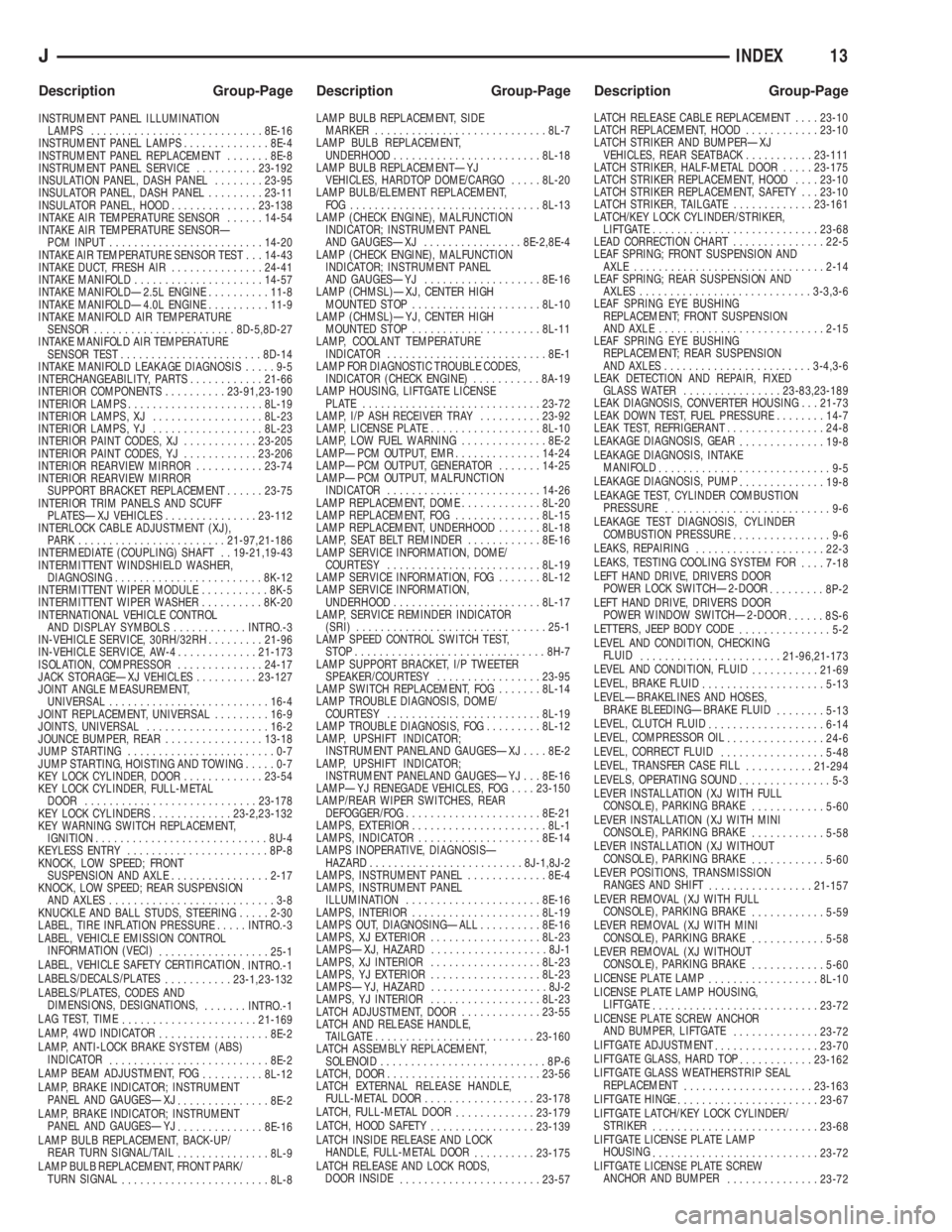
INSTRUMENT PANEL ILLUMINATION
LAMPS............................8E-16
INSTRUMENT PANEL LAMPS..............8E-4
INSTRUMENT PANEL REPLACEMENT.......8E-8
INSTRUMENT PANEL SERVICE..........23-192
INSULATION PANEL, DASH PANEL........23-95
INSULATOR PANEL, DASH PANEL.........23-11
INSULATOR PANEL, HOOD..............23-138
INTAKE AIR TEMPERATURE SENSOR......14-54
INTAKE AIR TEMPERATURE SENSORÐ
PCM INPUT.........................14-20
INTAKE AIR TEMPERATURE SENSOR TEST . . . 14-43
INTAKE DUCT, FRESH AIR...............24-41
INTAKE MANIFOLD.....................14-57
INTAKE MANIFOLDÐ2.5L ENGINE..........11-8
INTAKE MANIFOLDÐ4.0L ENGINE..........11-9
INTAKE MANIFOLD AIR TEMPERATURE
SENSOR.......................8D-5,8D-27
INTAKE MANIFOLD AIR TEMPERATURE
SENSOR TEST.......................8D-14
INTAKE MANIFOLD LEAKAGE DIAGNOSIS.....9-5
INTERCHANGEABILITY, PARTS............21-66
INTERIOR COMPONENTS..........23-91,23-190
INTERIOR LAMPS......................8L-19
INTERIOR LAMPS, XJ..................8L-23
INTERIOR LAMPS, YJ..................8L-23
INTERIOR PAINT CODES, XJ............23-205
INTERIOR PAINT CODES, YJ............23-206
INTERIOR REARVIEW MIRROR...........23-74
INTERIOR REARVIEW MIRROR
SUPPORT BRACKET REPLACEMENT......23-75
INTERIOR TRIM PANELS AND SCUFF
PLATESÐXJ VEHICLES...............23-112
INTERLOCK CABLE ADJUSTMENT (XJ),
PARK........................21-97,21-186
INTERMEDIATE (COUPLING) SHAFT . . 19-21,19-43
INTERMITTENT WINDSHIELD WASHER,
DIAGNOSING........................8K-12
INTERMITTENT WIPER MODULE...........8K-5
INTERMITTENT WIPER WASHER..........8K-20
INTERNATIONAL VEHICLE CONTROL
AND DISPLAY SYMBOLS............INTRO.-3
IN-VEHICLE SERVICE, 30RH/32RH.........21-96
IN-VEHICLE SERVICE, AW-4.............21-173
ISOLATION, COMPRESSOR..............24-17
JACK STORAGEÐXJ VEHICLES..........23-127
JOINT ANGLE MEASUREMENT,
UNIVERSAL..........................16-4
JOINT REPLACEMENT, UNIVERSAL.........16-9
JOINTS, UNIVERSAL....................16-2
JOUNCE BUMPER, REAR................13-18
JUMP STARTING........................0-7
JUMP STARTING, HOISTING AND TOWING.....0-7
KEY LOCK CYLINDER, DOOR.............23-54
KEY LOCK CYLINDER, FULL-METAL
DOOR............................23-178
KEY LOCK CYLINDERS.............23-2,23-132
KEY WARNING SWITCH REPLACEMENT,
IGNITION............................8U-4
KEYLESS ENTRY.......................8P-8
KNOCK, LOW SPEED; FRONT
SUSPENSION AND AXLE................2-17
KNOCK, LOW SPEED; REAR SUSPENSION
AND AXLES...........................3-8
KNUCKLE AND BALL STUDS, STEERING.....2-30
LABEL, TIRE INFLATION PRESSURE.....INTRO.-3
LABEL, VEHICLE EMISSION CONTROL
INFORMATION (VECI)
..................25-1
LABEL, VEHICLE SAFETY CERTIFICATION
. INTRO.-1
LABELS/DECALS/PLATES
...........23-1,23-132
LABELS/PLATES, CODES AND
DIMENSIONS, DESIGNATIONS,
.......INTRO.-1
LAG TEST, TIME
......................21-169
LAMP, 4WD INDICATOR
..................8E-2
LAMP, ANTI-LOCK BRAKE SYSTEM (ABS)
INDICATOR
..........................8E-2
LAMP BEAM ADJUSTMENT, FOG
..........8L-12
LAMP, BRAKE INDICATOR; INSTRUMENT
PANEL AND GAUGESÐXJ
...............8E-2
LAMP, BRAKE INDICATOR; INSTRUMENT
PANEL AND GAUGESÐYJ
..............8E-16
LAMP BULB REPLACEMENT, BACK-UP/
REAR TURN SIGNAL/TAIL
...............8L-9
LAMP BULB REPLACEMENT, FRONT PARK/
TURN SIGNAL
........................8L-8LAMP BULB REPLACEMENT, SIDE
MARKER............................8L-7
LAMP BULB REPLACEMENT,
UNDERHOOD........................8L-18
LAMP BULB REPLACEMENTÐYJ
VEHICLES, HARDTOP DOME/CARGO.....8L-20
LAMP BULB/ELEMENT REPLACEMENT,
FOG ...............................8L-13
LAMP (CHECK ENGINE), MALFUNCTION
INDICATOR; INSTRUMENT PANEL
AND GAUGESÐXJ................8E-2,8E-4
LAMP (CHECK ENGINE), MALFUNCTION
INDICATOR; INSTRUMENT PANEL
AND GAUGESÐYJ...................8E-16
LAMP (CHMSL)ÐXJ, CENTER HIGH
MOUNTED STOP.....................8L-10
LAMP (CHMSL)ÐYJ, CENTER HIGH
MOUNTED STOP.....................8L-11
LAMP, COOLANT TEMPERATURE
INDICATOR..........................8E-1
LAMP FOR DIAGNOSTIC TROUBLE CODES,
INDICATOR (CHECK ENGINE)...........8A-19
LAMP HOUSING, LIFTGATE LICENSE
PLATE .............................23-72
LAMP, I/P ASH RECEIVER TRAY..........23-92
LAMP, LICENSE PLATE..................8L-10
LAMP, LOW FUEL WARNING..............8E-2
LAMPÐPCM OUTPUT, EMR..............14-24
LAMPÐPCM OUTPUT, GENERATOR.......14-25
LAMPÐPCM OUTPUT, MALFUNCTION
INDICATOR.........................14-26
LAMP REPLACEMENT, DOME.............8L-20
LAMP REPLACEMENT, FOG..............8L-15
LAMP REPLACEMENT, UNDERHOOD.......8L-18
LAMP, SEAT BELT REMINDER............8E-16
LAMP SERVICE INFORMATION, DOME/
COURTESY.........................8L-19
LAMP SERVICE INFORMATION, FOG.......8L-12
LAMP SERVICE INFORMATION,
UNDERHOOD........................8L-17
LAMP, SERVICE REMINDER INDICATOR
(SRI)...............................25-1
LAMP SPEED CONTROL SWITCH TEST,
STOP...............................8H-7
LAMP SUPPORT BRACKET, I/P TWEETER
SPEAKER/COURTESY.................23-95
LAMP SWITCH REPLACEMENT, FOG.......8L-14
LAMP TROUBLE DIAGNOSIS, DOME/
COURTESY.........................8L-19
LAMP TROUBLE DIAGNOSIS, FOG.........8L-12
LAMP, UPSHIFT INDICATOR;
INSTRUMENT PANELAND GAUGESÐXJ....8E-2
LAMP, UPSHIFT INDICATOR;
INSTRUMENT PANELAND GAUGESÐYJ . . . 8E-16
LAMPÐYJ RENEGADE VEHICLES, FOG....23-150
LAMP/REAR WIPER SWITCHES, REAR
DEFOGGER/FOG......................8E-21
LAMPS, EXTERIOR......................8L-1
LAMPS, INDICATOR....................8E-14
LAMPS INOPERATIVE, DIAGNOSISÐ
HAZARD.........................8J-1,8J-2
LAMPS, INSTRUMENT PANEL.............8E-4
LAMPS, INSTRUMENT PANEL
ILLUMINATION......................8E-16
LAMPS, INTERIOR.....................8L-19
LAMPS OUT, DIAGNOSINGÐALL..........8E-16
LAMPS, XJ EXTERIOR..................8L-23
LAMPSÐXJ, HAZARD...................8J-1
LAMPS, XJ INTERIOR..................8L-23
LAMPS, YJ EXTERIOR..................8L-23
LAMPSÐYJ, HAZARD...................8J-2
LAMPS, YJ INTERIOR..................8L-23
LATCH ADJUSTMENT, DOOR.............23-55
LATCH AND RELEASE HANDLE,
TAILGATE..........................23-160
LATCH ASSEMBLY REPLACEMENT,
SOLENOID...........................8P-6
LATCH, DOOR.........................23-56
LATCH EXTERNAL RELEASE HANDLE,
FULL-METAL DOOR..................23-178
LATCH, FULL-METAL DOOR
.............23-179
LATCH, HOOD SAFETY
.................23-139
LATCH INSIDE RELEASE AND LOCK
HANDLE, FULL-METAL DOOR
..........23-175
LATCH RELEASE AND LOCK RODS,
DOOR INSIDE
.......................23-57LATCH RELEASE CABLE REPLACEMENT....23-10
LATCH REPLACEMENT, HOOD............23-10
LATCH STRIKER AND BUMPERÐXJ
VEHICLES, REAR SEATBACK...........23-111
LATCH STRIKER, HALF-METAL DOOR.....23-175
LATCH STRIKER REPLACEMENT, HOOD....23-10
LATCH STRIKER REPLACEMENT, SAFETY . . . 23-10
LATCH STRIKER, TAILGATE.............23-161
LATCH/KEY LOCK CYLINDER/STRIKER,
LIFTGATE...........................23-68
LEAD CORRECTION CHART...............22-5
LEAF SPRING; FRONT SUSPENSION AND
AXLE...............................2-14
LEAF SPRING; REAR SUSPENSION AND
AXLES............................3-3,3-6
LEAF SPRING EYE BUSHING
REPLACEMENT; FRONT SUSPENSION
AND AXLE...........................2-15
LEAF SPRING EYE BUSHING
REPLACEMENT; REAR SUSPENSION
AND AXLES........................3-4,3-6
LEAK DETECTION AND REPAIR, FIXED
GLASS WATER................23-83,23-189
LEAK DIAGNOSIS, CONVERTER HOUSING . . . 21-73
LEAK DOWN TEST, FUEL PRESSURE........14-7
LEAK TEST, REFRIGERANT................24-8
LEAKAGE DIAGNOSIS, GEAR
..............19-8
LEAKAGE DIAGNOSIS, INTAKE
MANIFOLD
............................9-5
LEAKAGE DIAGNOSIS, PUMP
..............19-8
LEAKAGE TEST, CYLINDER COMBUSTION
PRESSURE
...........................9-6
LEAKAGE TEST DIAGNOSIS, CYLINDER
COMBUSTION PRESSURE
................9-6
LEAKS, REPAIRING
.....................22-3
LEAKS, TESTING COOLING SYSTEM FOR
....7-18
LEFT HAND DRIVE, DRIVERS DOOR
POWER LOCK SWITCHÐ2-DOOR
.........8P-2
LEFT HAND DRIVE, DRIVERS DOOR
POWER WINDOW SWITCHÐ2-DOOR
......8S-6
LETTERS, JEEP BODY CODE
...............5-2
LEVEL AND CONDITION, CHECKING
FLUID
.......................21-96,21-173
LEVEL AND CONDITION, FLUID
...........21-69
LEVEL, BRAKE FLUID
....................5-13
LEVELÐBRAKELINES AND HOSES,
BRAKE BLEEDINGÐBRAKE FLUID
........5-13
LEVEL, CLUTCH FLUID
...................6-14
LEVEL, COMPRESSOR OIL
................24-6
LEVEL, CORRECT FLUID
.................5-48
LEVEL, TRANSFER CASE FILL
...........21-294
LEVELS, OPERATING SOUND
...............5-3
LEVER INSTALLATION (XJ WITH FULL
CONSOLE), PARKING BRAKE
............5-60
LEVER INSTALLATION (XJ WITH MINI
CONSOLE), PARKING BRAKE
............5-58
LEVER INSTALLATION (XJ WITHOUT
CONSOLE), PARKING BRAKE
............5-60
LEVER POSITIONS, TRANSMISSION
RANGES AND SHIFT
.................21-157
LEVER REMOVAL (XJ WITH FULL
CONSOLE), PARKING BRAKE
............5-59
LEVER REMOVAL (XJ WITH MINI
CONSOLE), PARKING BRAKE
............5-58
LEVER REMOVAL (XJ WITHOUT
CONSOLE), PARKING BRAKE
............5-60
LICENSE PLATE LAMP
..................8L-10
LICENSE PLATE LAMP HOUSING,
LIFTGATE
...........................23-72
LICENSE PLATE SCREW ANCHOR
AND BUMPER, LIFTGATE
..............23-72
LIFTGATE ADJUSTMENT
.................23-70
LIFTGATE GLASS, HARD TOP
............23-162
LIFTGATE GLASS WEATHERSTRIP SEAL
REPLACEMENT
.....................23-163
LIFTGATE HINGE
.......................23-67
LIFTGATE LATCH/KEY LOCK CYLINDER/
STRIKER
...........................23-68
LIFTGATE LICENSE PLATE LAMP
HOUSING
...........................23-72
LIFTGATE LICENSE PLATE SCREW
ANCHOR AND BUMPER
...............23-72
JINDEX13
Description Group-Page Description Group-Page Description Group-Page