1994 JEEP CHEROKEE headlamp
[x] Cancel search: headlampPage 440 of 1784
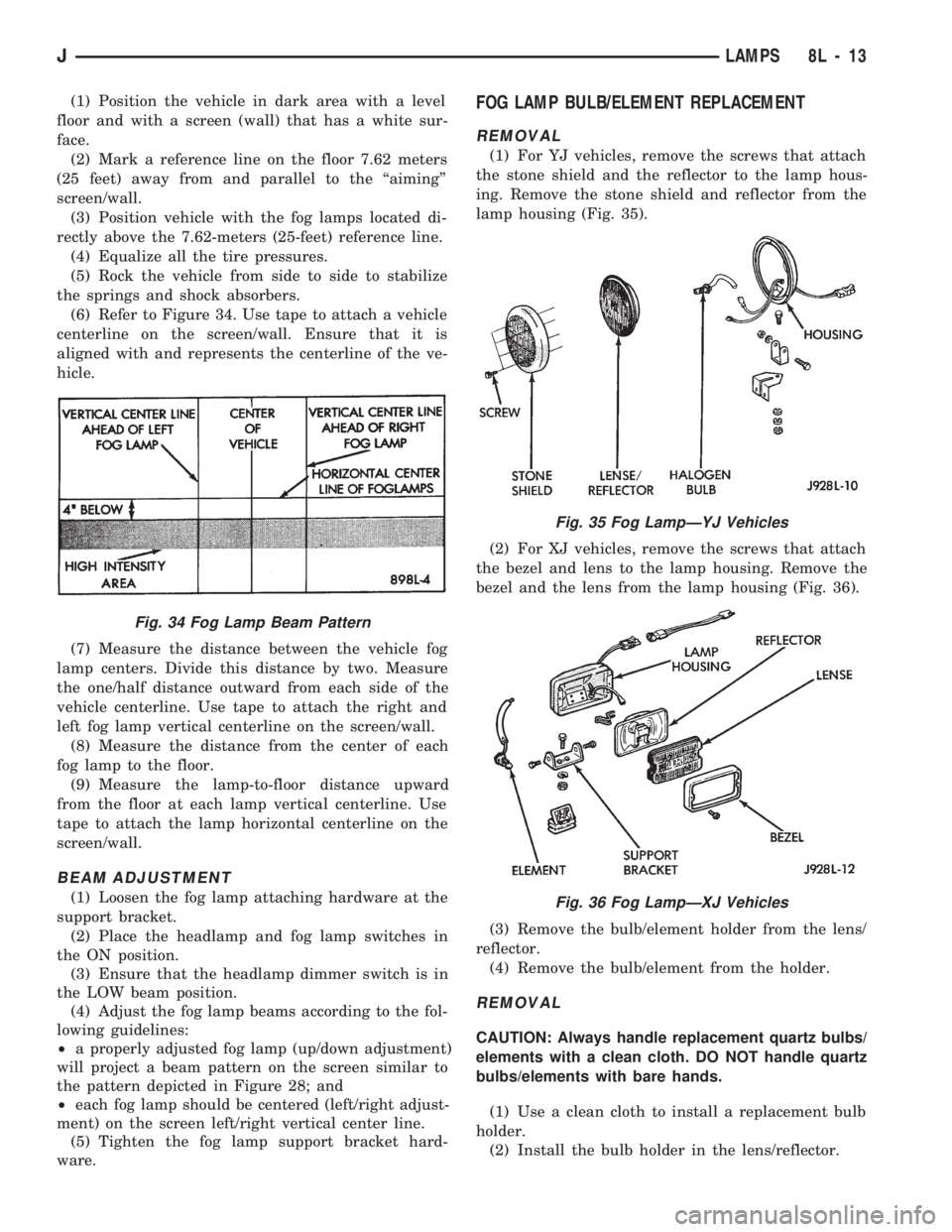
(1) Position the vehicle in dark area with a level
floor and with a screen (wall) that has a white sur-
face.
(2) Mark a reference line on the floor 7.62 meters
(25 feet) away from and parallel to the ``aiming''
screen/wall.
(3) Position vehicle with the fog lamps located di-
rectly above the 7.62-meters (25-feet) reference line.
(4) Equalize all the tire pressures.
(5) Rock the vehicle from side to side to stabilize
the springs and shock absorbers.
(6) Refer to Figure 34. Use tape to attach a vehicle
centerline on the screen/wall. Ensure that it is
aligned with and represents the centerline of the ve-
hicle.
(7) Measure the distance between the vehicle fog
lamp centers. Divide this distance by two. Measure
the one/half distance outward from each side of the
vehicle centerline. Use tape to attach the right and
left fog lamp vertical centerline on the screen/wall.
(8) Measure the distance from the center of each
fog lamp to the floor.
(9) Measure the lamp-to-floor distance upward
from the floor at each lamp vertical centerline. Use
tape to attach the lamp horizontal centerline on the
screen/wall.
BEAM ADJUSTMENT
(1) Loosen the fog lamp attaching hardware at the
support bracket.
(2) Place the headlamp and fog lamp switches in
the ON position.
(3) Ensure that the headlamp dimmer switch is in
the LOW beam position.
(4) Adjust the fog lamp beams according to the fol-
lowing guidelines:
²a properly adjusted fog lamp (up/down adjustment)
will project a beam pattern on the screen similar to
the pattern depicted in Figure 28; and
²each fog lamp should be centered (left/right adjust-
ment) on the screen left/right vertical center line.
(5) Tighten the fog lamp support bracket hard-
ware.
FOG LAMP BULB/ELEMENT REPLACEMENT
REMOVAL
(1) For YJ vehicles, remove the screws that attach
the stone shield and the reflector to the lamp hous-
ing. Remove the stone shield and reflector from the
lamp housing (Fig. 35).
(2) For XJ vehicles, remove the screws that attach
the bezel and lens to the lamp housing. Remove the
bezel and the lens from the lamp housing (Fig. 36).
(3) Remove the bulb/element holder from the lens/
reflector.
(4) Remove the bulb/element from the holder.
REMOVAL
CAUTION: Always handle replacement quartz bulbs/
elements with a clean cloth. DO NOT handle quartz
bulbs/elements with bare hands.
(1) Use a clean cloth to install a replacement bulb
holder.
(2) Install the bulb holder in the lens/reflector.
Fig. 34 Fog Lamp Beam Pattern
Fig. 35 Fog LampÐYJ Vehicles
Fig. 36 Fog LampÐXJ Vehicles
JLAMPS 8L - 13
Page 441 of 1784
(3) For XJ vehicles, position the bezel and the lens
on the lamp housing. Install the screws that attach
the bezel and lens to the lamp housing. Tighten the
screws securely.
(4) For YJ vehicles, position the stone shield and
reflector on the lamp housing. Install the screws that
attach the stone shield and the reflector to the lamp
housing. Tighten the screws securely.
FOG LAMP SWITCH REPLACEMENT
REMOVALÐXJ VEHICLES
The fog lamp switch is located on the instrument
panel at the left of the steering column.
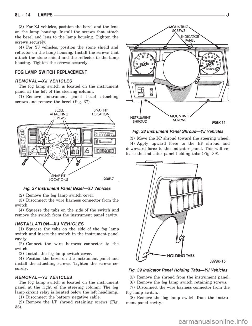
(1) Remove instrument panel bezel attaching
screws and remove the bezel (Fig. 37).
(2) Remove the fog lamp switch cover.
(3) Disconnect the wire harness connector from the
switch.
(4) Squeeze the tabs on the side of the switch and
remove the switch from the instrument panel cavity.
INSTALLATIONÐXJ VEHICLES
(1) Squeeze the tabs on the side of the fog lamp
switch and insert the switch in the instrument panel
cavity.
(2) Connect the wire harness connector to the
switch.
(3) Install the fog lamp switch cover.
(4) Position the bezel on the instrument panel and
install the attaching screws. Tighten the screws se-
curely.
REMOVALÐYJ VEHICLES
The fog lamp switch is located on the instrument
panel at the right of the steering column. The fog
lamp circuit relay is located below the left headlamp.
(1) Disconnect the battery negative cable.
(2) Remove the I/P shroud retaining screws (Fig.
36).(3) Move the I/P shroud toward the steering wheel.
(4) Apply upward force to the I/P shroud and
downward force to the indicator panel. This will re-
lease the indicator panel holding tabs (Fig. 39).
(5) Remove the shroud from the instrument panel.
(6) Remove the fog lamp switch retaining screws.
(7) Disconnect the wire harness connector from the
fog lamp switch.
(8) Remove the fog lamp switch from the instru-
ment panel cavity.
Fig. 37 Instrument Panel BezelÐXJ Vehicles
Fig. 38 Instrument Panel ShroudÐYJ Vehicles
Fig. 39 Indicator Panel Holding TabsÐYJ Vehicles
8L - 14 LAMPSJ
Page 442 of 1784
INSTALLATIONÐYJ VEHICLES
(1) Position the fog lamp switch in the instrument
panel cavity and connect the wire harness connector
to the switch.
(2) Install the fog lamp switch retaining screws.
Tighten the screws securely.
(3) Position the I/P shroud under the steering col-
umn.
(4) Slide the indicator panel holding tabs into the
shroud notches.
(5) Place the assembled I/P shroud over the indica-
tor lamp foam gasket.
The foam gasket located on the back side of
the indicator panel overlay is fragile. If it is ei-
ther torn or distorted, replace it.
(6) Install and tighten the indicator panel retain-
ing screws.
(7) Install the remaining shroud screws. Tighten
the screws securely.
(8) Connect the battery negative cable.
FOG LAMP REPLACEMENT
REMOVALÐXJ VEHICLES
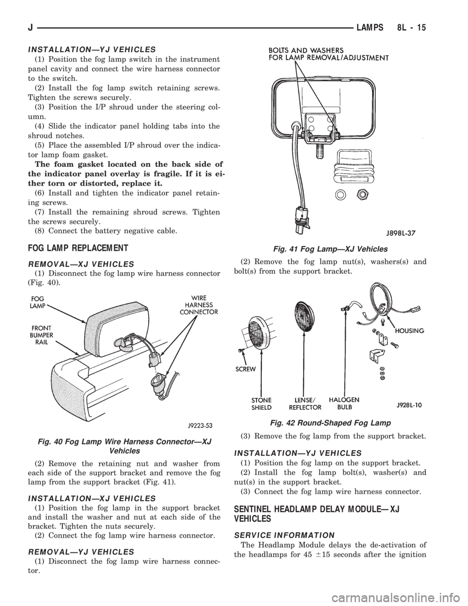
(1) Disconnect the fog lamp wire harness connector
(Fig. 40).
(2) Remove the retaining nut and washer from
each side of the support bracket and remove the fog
lamp from the support bracket (Fig. 41).
INSTALLATIONÐXJ VEHICLES
(1) Position the fog lamp in the support bracket
and install the washer and nut at each side of the
bracket. Tighten the nuts securely.
(2) Connect the fog lamp wire harness connector.
REMOVALÐYJ VEHICLES
(1) Disconnect the fog lamp wire harness connec-
tor.(2) Remove the fog lamp nut(s), washers(s) and
bolt(s) from the support bracket.
(3) Remove the fog lamp from the support bracket.
INSTALLATIONÐYJ VEHICLES
(1) Position the fog lamp on the support bracket.
(2) Install the fog lamp bolt(s), washer(s) and
nut(s) in the support bracket.
(3) Connect the fog lamp wire harness connector.
SENTINEL HEADLAMP DELAY MODULEÐXJ
VEHICLES
SERVICE INFORMATION
The Headlamp Module delays the de-activation of
the headlamps for 45615 seconds after the ignition
Fig. 40 Fog Lamp Wire Harness ConnectorÐXJ
Vehicles
Fig. 41 Fog LampÐXJ Vehicles
Fig. 42 Round-Shaped Fog Lamp
JLAMPS 8L - 15
Page 443 of 1784
switch is turned OFF. The driver engages the module
by turning the ignition switch OFF, then turning the
headlamps OFF.
The headlamp delay module is located behind the
I/P next to the headlamp switch.
HEADLAMP DELAY MODULE REPLACEMENTÐXJ
VEHICLES
The headlamp delay module is attached to the in-
side of the instrument panel to the right of the head-
lamp switch.
REMOVAL
(1) Remove the lower instrument panel.
(2) Remove the screw that attaches the module to
the inside of the instrument panel.
(3) Disconnect the wire harness connector and re-
move the module from the instrument panel.
INSTALLATION
(1) Position the module inside the I/P and connect
the wire harness connector to the module.
(2) Install the screw that attaches the module to
the inside of the instrument panel.(3) Remove the lower instrument panel.
HEADLAMP DELAY FUNCTION TROUBLE
DIAGNOSISÐXJ VEHICLES
DELAY FUNCTION INOPERATIVE
(1) Remove, inspect and test the HD LP DLY fuse.
Replace if defective.
(2) Remove the delay module from the I/P. Do not
disconnect the wire harness connector. Turn the igni-
tion switch to the RUN position. Place the headlamp
switch in headlamps ON position. Turn the ignition
to the OFF position for a resistance test.
(3) Measure the resistance from the delay module
terminal 4 to vehicle body ground. The ohmmeter
should indicate zero ohms. If not, repair the open cir-
cuit in the wire harness to vehicle body ground.
(4) Measure the voltage between the delay module
terminal 8 and vehicle body ground. The voltmeter
should indicate battery voltage. If not, repair the
open circuit in the wire harness to the instrument
cluster indicator connector terminal 14.
(5) Measure the voltage between the delay module
terminal 6 and vehicle body ground. The voltmeter
should indicate battery voltage. If not, repair the
open circuit in the wire harness to the headlamp
switch.
(6) Measure the voltage between the delay module
terminal 2 and vehicle body ground. The voltmeter
should indicate battery voltage. If not, repair the
open circuit in the wire harness to the fuse.
DAYTIME RUNNING LIGHTS (CANADA ONLY)
SERVICE INFORMATION
The Daytime Running Lights (Headlamps) System
is installed on vehicles manufactured for sale in Can-
ada only. The headlamps are illuminated when the
ignition switch is turned to the ON position. The
DRL module receives a vehicle-moving signal from
the vehicle speed sensor. This provides a constant
headlamps-oncondition as long as the vehicle is
moving. The lamps are illuminated at less than 50
percent of normal intensity.
DRL MODULE REPLACEMENT
REMOVALÐXJ VEHICLES
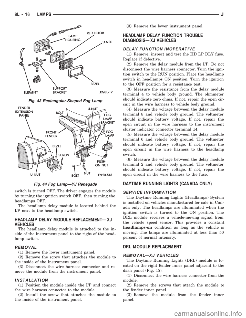
The Daytime Running Lights (DRL) module is lo-
cated on the right fender inner panel adjacent to the
dash panel (Fig. 45).
(1) Disconnect the wire harness connector from the
module.
(2) Remove the screws that attach the module to
the fender inner panel.
(3) Remove the module from the fender inner
panel.
Fig. 43 Rectangular-Shaped Fog Lamp
Fig. 44 Fog LampÐYJ Renegade
8L - 16 LAMPSJ
Page 446 of 1784
INTERIOR LAMPS
INDEX
page page
Dome Lamp Replacement.................. 20
Dome/Courtesy Lamp Service Information...... 19
Dome/Courtesy Lamp Trouble Diagnosis....... 19
Hardtop Dome/Cargo Lamp Bulb ReplacementÐYJ
Vehicles.............................. 20Illuminated Entry System Service Information . . . 20
Illuminated Entry System Trouble Diagnosis.... 21
Lighted Vanity Mirror...................... 19
Lighted Vanity Mirror Trouble Diagnosis....... 19
Overhead ConsoleÐXJ Vehicles............. 20
DOME/COURTESY LAMP SERVICE INFORMATION
XJ VEHICLES
Voltage is applied at all times via the dome lamp
fuse to each of the interior lamp bulbs. The interior
lamp bulbs illuminate when they are connected to
body ground via the switch:
²headlamp switch,
²glove box switch,
²door pillar switch, and
²liftgate switch (if the cargo lamp is ON.)
If equipped with Security Alarm Module, refer to
Group 8QÐVehicle Theft Security System.
YJ VEHICLES
The dome/cargo and courtesy lamps are controlled
via ON/OFF switches. The ON/OFF switches are in
the lamp ground circuits. Voltage via the dome/cour-
tesy lamp fuse is applied directly to the lamp bulbs.
When either door is opened, the door pillar switch
contacts close and provide a direct path to vehicle
body ground.
The cargo/cargo and courtesy lamps can also be
turned on via the interior lamp illumination rheo-
stat.
DOME/COURTESY LAMP TROUBLE DIAGNOSIS
ALL LAMPS INOPERATIVE
(1) Rotate the headlamp switch rheostat clockwise.
The lamps should light. If not OK, remove, inspect
and test the dome lamp fuse. Replace if bad.
(2) If the fuse is OK, repair the open circuit in the
wire harness to vehicle body ground.
ONE LAMP INOPERATIVE
(1) Measure the resistance across the bulb holder
terminals. The ohmmeter should indicate zero ohms.
If not, replace the bulb.
(2) Measure the voltage between the voltage side
of the bulb holder and vehicle body ground. The volt-
meter should indicate battery voltage. If not, repair
the open circuit in the wire harness to the splice.
LAMPS INOPERATIVE WITH ONE OR MORE
DOORS OPENED
(1) Remove the inoperative switch from the door
pillar and connect the switch wire directly to ground.
The lamp should light.
(2) If not, check for an open circuit in black
(ground) wire. Repair as necessary. If lamps still do
not light, replace the switch.
LIGHTED VANITY MIRROR
SERVICE INFORMATIONÐXJ VEHICLES
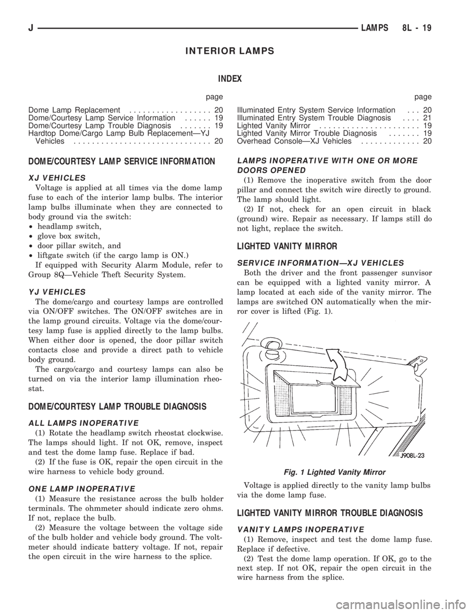
Both the driver and the front passenger sunvisor
can be equipped with a lighted vanity mirror. A
lamp located at each side of the vanity mirror. The
lamps are switched ON automatically when the mir-
ror cover is lifted (Fig. 1).
Voltage is applied directly to the vanity lamp bulbs
via the dome lamp fuse.
LIGHTED VANITY MIRROR TROUBLE DIAGNOSIS
VANITY LAMPS INOPERATIVE
(1) Remove, inspect and test the dome lamp fuse.
Replace if defective.
(2) Test the dome lamp operation. If OK, go to the
next step. If not OK, repair the open circuit in the
wire harness from the splice.
Fig. 1 Lighted Vanity Mirror
JLAMPS 8L - 19
Page 488 of 1784
CHIME/BUZZER WARNING SYSTEMS
CONTENTS
page page
GENERAL.............................. 1
IGNITION KEY WARNING SWITCH REPLACEMENT.4OPERATION/DIAGNOSIS.................. 1
GENERAL
The buzzer or optional chime module is mounted on
the left side of the fuse block (above and to the left of
the brake/clutch pedal). The buzzer or chime sounds
an audible warning tone in any of the following con-
ditions:
²Vehicle lights are ON when the ignition has been
switched OFF and the key is removed and then the
driver's door is opened (except YJ).²The key is in the ignition and the driver's door is
open (On some vehicles, the buzzer will not sound if
the ignition switch is in the ON position).
²The ignition is switched ON and the driver's seat
belt is not buckled. Buzzer will quit after 4 to 8 sec-
onds. Besides the buzzer, a seat belt indicator lamp
turns on as a reminder to fasten seat belt.
OPERATION/DIAGNOSIS
OPERATION
Battery voltage for module operation is supplied to
two pins. Voltage is always present at pin 7. Pin 1
receives voltage when the ignition switch is in the
ON or START position.
SEAT BELT WARNING
The seat belt warning system uses both visual and
audible signals. These consist of a buzzer that is part
of a combined seat belt and key warning buzzer and
a red light on the instrument panel.
The system will always illuminate the seat belt
warning lamp for four to eight seconds when the ig-
nition switch is turned to the ON position. Also, only
if the driver does not fasten his seat belt, the buzzer
will sound during the same time interval. Passenger
belts are not connected to the system.
A timed buzzer-relay is used to operate the system
for the time period. It has a time delay mechanism
and buzzer assembly. Only the driver's seat belt
buckle has a switch that is connected to the system.
KEY-IN-IGNITION WARNING
To sound the key-in-ignition warning, the following
must occur:
²the ignition key warning switch must be closed
²the driver's door jamb switch must be closed.
These conditions ground pin 6 of the module. These
switches are closed when the key is in the ignition
and the driver's door is open.On some vehicles the chime/buzzer will not
sound if the door is open and the key is in the
ON position.
LIGHTS-ON WARNING (EXCEPT YJ)
To sound the lights-on warning, the following must
occur:
²the headlamp switch must be closed
²the driver's door jamb switch must be closed.
These conditions ground pin 6 of the module. These
switches are closed when the headlamp switch is ON
and the driver's door is open.
DIAGNOSIS
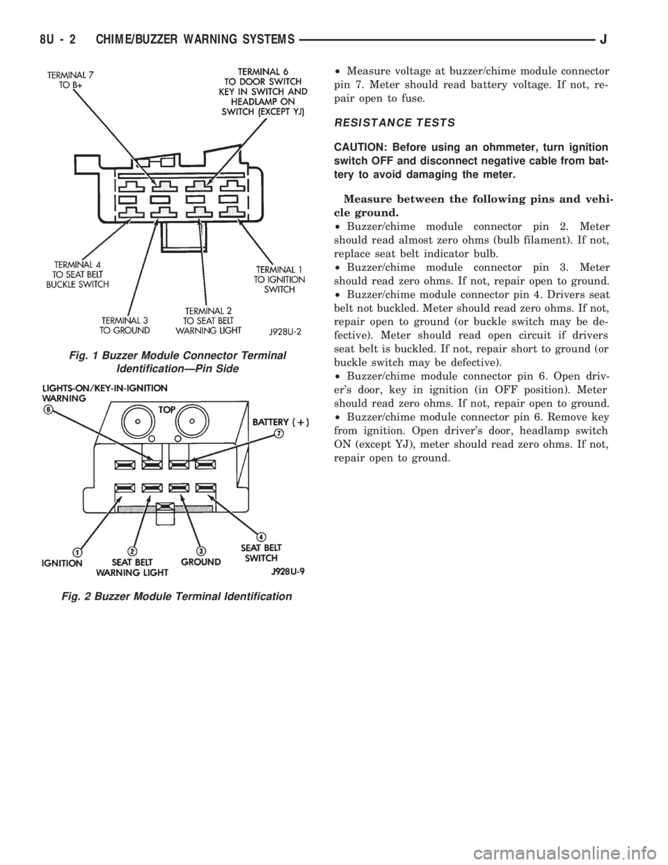
If the buzzer/chime unit does not operate as de-
scribed, check the two fuses for pins 1 and 7 (Figs. 1
and 2) and replace as required. If the fuses are not
defective, perform the following tests to determine if
the problem is in the module or in the wiring. Using
a flat head screwdriver, release the locking plastic
clip while carefully pulling out the module. Plug in a
known good module and check its operation. If the
problem is not corrected by replacing the module, re-
move the module and continue as follows:
VOLTAGE TESTS
Ignition in ON position, measure between the
following pins and vehicle ground.
²Measure voltage at buzzer/chime module connector
pin 1. Meter should read battery voltage. If not, re-
pair open to ignition switch.
Turn ignition OFF and remove the key from the ig-
nition.
JCHIME/BUZZER WARNING SYSTEMS 8U - 1
Page 489 of 1784
²Measure voltage at buzzer/chime module connector
pin 7. Meter should read battery voltage. If not, re-
pair open to fuse.
RESISTANCE TESTS
CAUTION: Before using an ohmmeter, turn ignition
switch OFF and disconnect negative cable from bat-
tery to avoid damaging the meter.
Measure between the following pins and vehi-
cle ground.
²Buzzer/chime module connector pin 2. Meter
should read almost zero ohms (bulb filament). If not,
replace seat belt indicator bulb.
²Buzzer/chime module connector pin 3. Meter
should read zero ohms. If not, repair open to ground.
²Buzzer/chime module connector pin 4. Drivers seat
belt not buckled. Meter should read zero ohms. If not,
repair open to ground (or buckle switch may be de-
fective). Meter should read open circuit if drivers
seat belt is buckled. If not, repair short to ground (or
buckle switch may be defective).
²Buzzer/chime module connector pin 6. Open driv-
er's door, key in ignition (in OFF position). Meter
should read zero ohms. If not, repair open to ground.
²Buzzer/chime module connector pin 6. Remove key
from ignition. Open driver's door, headlamp switch
ON (except YJ), meter should read zero ohms. If not,
repair open to ground.
Fig. 2 Buzzer Module Terminal Identification
Fig. 1 Buzzer Module Connector Terminal
IdentificationÐPin Side
8U - 2 CHIME/BUZZER WARNING SYSTEMSJ
Page 566 of 1784
WIRING DIAGRAMS YJ
ALPHABETICAL INDEX
Wiring Diagram Name Sheet Number
ABS Accelerator Sensor........................59
ABS Control Module.....................57, 58, 59
ABS Control Module Connector...................60
ABS Motor Pump Relay........................57
ABS Power Relay............................57
A/C Blower Switch............................50
A/C Compressor.............................49
A/C Low Pressure Switch.......................49
A/C Relay.................................49
A/C Thermostat..............................50
Accessory Illumination.........................32
Air Conditioning System (4.0L).................49, 50
A/C Blower Switch..........................50
A/C Compressor............................49
A/C Low Pressure Switch.....................49
A/C Relay................................49
A/C Thermostat............................50
Field Jumper..............................50
Powertrain Control Module.....................49
Anti-Lock Brake System (TEVES).............57, 58, 59
ABS Accelerator Sensor.......................59
ABS Control Module....................57, 58, 59
ABS Motor Pump Relay.......................57
ABS Power Relay...........................57
Brake Pedal Travel Sensor.....................57
Data Link Connector.........................57
Diode..................................58
Hydraulic Actuation Unit......................58
Left Front Wheel Sensor......................59
Left Rear Wheel Sensor.......................59
Power Distribution Center.....................57
Pump Motor..............................57
Pump Motor Sensor.........................57
Right Front Wheel Sensor.....................59
Right Rear Wheel Sensor......................59
Automatic Shut-Down Relay...................11, 17
Back-Up Lamps...........................51, 52
Back-Up Lamp Switch..........................7
Battery................................1,3,5
Blower Motor...............................47
Blower Resistor.............................47
Blower Switch..............................47
Body Harness Connector........................36
Brake Pedal Travel Sensor.......................57
Brake Warning Switch..........................9
Bulkhead Connector........................65, 66
Buzzer Module..............................36
Camshaft Position Sensor....................12, 18
Center High Mounted Stop Lamp..................52
Charging System 2.5L Engine...................3,4
Battery..................................3
Generator.................................3
Power Distribution Center......................4Wiring Diagram Name Sheet Number
Charging System 4.0L Engine...................5,6
Battery..................................5
Generator.................................5
Power Distribution Center......................6
Cigar Lighter...............................24
Circuit Breakers
Headlamp Switch.........................1,29
#11 (W/Wiper).....................2,10,38,39
Clock....................................45
Cluster Connector............................41
Crankshaft Position Sensor...................12, 18
Data Link Connector.....................13, 19, 57
Daytime Running Lamp Module...................28
Dimmer Switch............................1,29
Dome and Courtesy Lamps......................35
Dome Lamp..............................35
Left Courtesy Lamp.........................35
Left Front Door Jamb Switch...................35
Right Courtesy Lamp........................35
Right Front Door Jamb Switch..................35
Dome Lamp................................35
Electrically Tuned Radio with Clock.................45
Electrical Schematic of Cluster....................42
Electrical Schematic of Gauge Package..............44
Electronic Speedometer.........................42
Electronic Tachometer..........................42
Engine Coolant Temp Gauge.....................44
Engine Coolant Temperature Sensor..............15, 21
Engine Oil Pressure and Temperature System..........23
Engine Coolant Temperature Sending Unit...........23
Engine Oil Pressure Sending Unit................23
Engine Oil Pressure Gauge......................44
Engine Starter System........................2,7
Back-Up Lamp Switch........................7
Engine Starter Motor.........................7
Engine Starter Relay..........................7
Park/Neutral Position Switch....................7
Engine Wiring Connector (16 Way).................69
4-WD Command Trac Switch......................8
Field Jumper...............................50
Fog Lamp Relays............................30
Fog Lamp Switch............................30
Front End Lighting.........................25, 26
Left Fog Lamp.............................25
Left Headlamp.............................25
Left Park and Turn Signal Lamp.................25
Left Side Marker Lamp.......................25
Right Fog Lamp............................26
Right Headlamp............................26
Right Park and Turn Signal Lamp................26
Right Side Marker Lamp......................26
Front End Lighting (Canada)...................27, 28
Daytime Running Lamp Module.................28
JWIRING DIAGRAMS 8W - 73