1994 JEEP CHEROKEE Engine mount location
[x] Cancel search: Engine mount locationPage 897 of 1784
(29) Disconnect the engine speed sensor wire con-
nection.
(30) Remove the exhaust pipe support.
(31) Remove the flywheel/converter housing access
cover.
(32)Vehicles with Automatic Transmission:
(a) Mark the converter and drive plate location.
(b) Remove the converter-to-drive plate bolts.
(33) Remove the upper flywheel/converter housing
bolts and loosen the bottom bolts.
(34) Remove the engine mount cushion-to-engine
compartment bracket bolts.
(35) Lower the vehicle.
(36) Attach a lifting device to the engine.
(37) Raise the engine off the front supports.
(38) Place a support or floor jack under the con-
verter (or flywheel) housing.
(39) Remove the remaining converter (or flywheel)
housing bolts.
(40) Lift the engine out of the engine compart-
ment.
INSTALLATION
CAUTION: When installing the engine into a vehicle
equipped with an automatic transmission, be care-
ful not to damage the trigger wheel on the flywheel.
(1) Attach a lifting device to the engine and lower
the engine into the engine compartment. For easier
installation, it may be necessary to remove the en-
gine mount cushions from the engine mount bracket
as an aide in alignment of the engine to the trans-
mission.
(2)Vehicles with Manual Transmission:
(a) Insert the transmission shaft into the clutch
spline.
(b) Align the flywheel housing with the engine.
(c) Install and tighten the flywheel housing
lower bolts finger tight.(3)Vehicles with Automatic Transmission:
(a) Align the transmission torque converter
housing with the engine.
(b) Loosely install the converter housing lower
bolts and install the next higher bolt and nut on
each side.
(c) Tighten all 4 bolts finger tight.
(4) Install the engine mount cushions (if removed).
(5) Lower the engine and engine mount cushions
onto the engine compartment brackets. Install the
bolts and finger tighten the nuts.
(6) Remove the engine lifting device.
(7) Raise and support the vehicle.
(8) Install the remaining flywheel/converter hous-
ing bolts. Tighten all bolts to 38 Nzm (28 ft. lbs.)
torque.
(9)Vehicles with Automatic Transmission:
(a) Install the converter-to-drive plate bolts.
(b) Ensure the installation reference marks are
aligned.
(10) Install the flywheel/converter housing access
cover.
(11) Install the exhaust pipe support and tighten
the screw.
(12) Tighten the engine mount-to-bracket bolts.
(13) Connect the engine speed sensor wire connec-
tions and tighten the screws.
(14) Connect the exhaust pipe to the manifold.
(15) Install the starter motor and connect the ca-
ble.
(16) Connect the wires to the starter motor sole-
noid.
(17) Lower the vehicle.
(18) Connect all the vacuum hoses and wire con-
nectors identified during engine removal.
(19) If equipped with power steering:
(a) Remove the protective caps
(b) Connect the hoses to the fittings at the steer-
ing gear. Tighten the nut to 52 Nzm (38 ft. lbs.)
torque.
(c) Fill the pump reservoir with fluid.
(20) Install the power brake vacuum check valve
to the booster, if equipped.
(21) Connect the fuel inlet and return hoses at the
fuel rail. Verify that the quick-connect fitting assem-
bly fits securely over the fuel lines by giving the fuel
lines a firm tug.
(22) Install the fuel line bracket to the intake
manifold.
(23) Connect the distributor electrical connector
and oil pressure switch connector.
(24) Connect the injection system wire harness
connector on the dash panel.
(25) Connect the line pressure cable (if equipped
with automatic transmission).
(26) Connect the speed control cable, if equipped.
(27) Connect the throttle cable linkages.
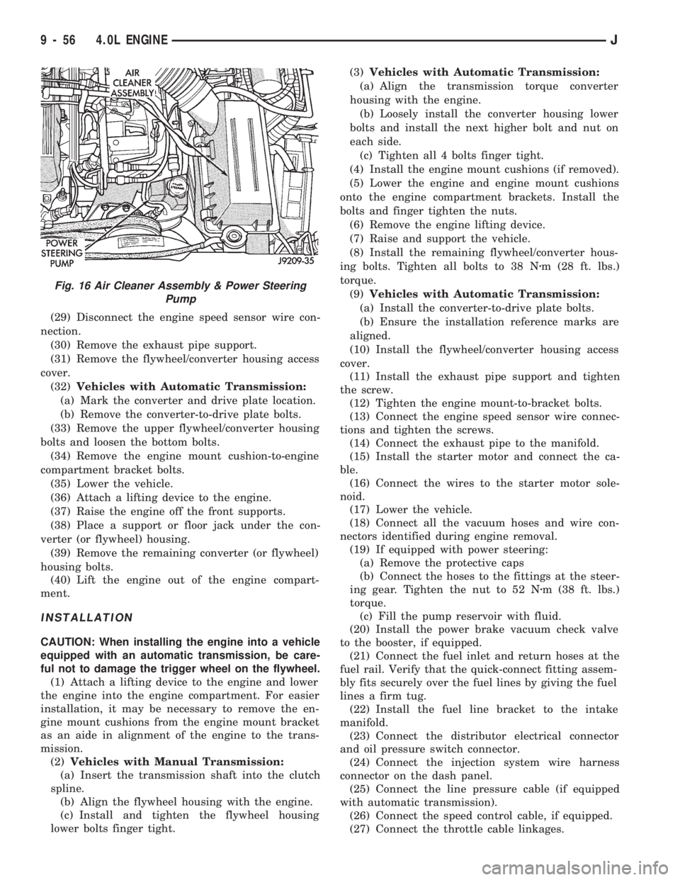
Fig. 16 Air Cleaner Assembly & Power Steering
Pump
9 - 56 4.0L ENGINEJ
Page 901 of 1784
(3) Check for rocker arm bridges which are caus-
ing misalignment of the rocker arm to valve tip area.
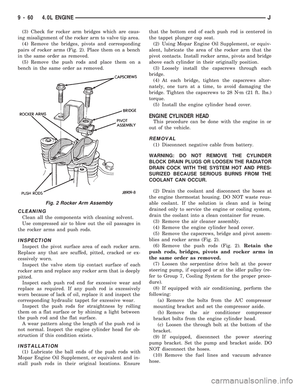
(4) Remove the bridges, pivots and corresponding
pairs of rocker arms (Fig. 2). Place them on a bench
in the same order as removed.
(5) Remove the push rods and place them on a
bench in the same order as removed.
CLEANING
Clean all the components with cleaning solvent.
Use compressed air to blow out the oil passages in
the rocker arms and push rods.
INSPECTION
Inspect the pivot surface area of each rocker arm.
Replace any that are scuffed, pitted, cracked or ex-
cessively worn.
Inspect the valve stem tip contact surface of each
rocker arm and replace any rocker arm that is deeply
pitted.
Inspect each push rod end for excessive wear and
replace as required. If any push rod is excessively
worn because of lack of oil, replace it and inspect the
corresponding hydraulic tappet for excessive wear.
Inspect the push rods for straightness by rolling
them on a flat surface or by shining a light between
the push rod and the flat surface.
A wear pattern along the length of the push rod is
not normal. Inspect the engine cylinder head for ob-
struction if this condition exists.
INSTALLATION
(1) Lubricate the ball ends of the push rods with
Mopar Engine Oil Supplement, or equivalent and in-
stall push rods in their original locations. Ensurethat the bottom end of each push rod is centered in
the tappet plunger cap seat.
(2) Using Mopar Engine Oil Supplement, or equiv-
alent, lubricate the area of the rocker arm that the
pivot contacts. Install rocker arms, pivots and bridge
above each cylinder in their originally position.
(3) Loosely install the capscrews through each
bridge.
(4) At each bridge, tighten the capscrews alter-
nately, one turn at a time, to avoid damaging the
bridge. Tighten the capscrews to 28 Nzm (21 ft. lbs.)
torque.
(5) Install the engine cylinder head cover.
ENGINE CYLINDER HEAD
This procedure can be done with the engine in or
out of the vehicle.
REMOVAL
(1) Disconnect negative cable from battery.
WARNING: DO NOT REMOVE THE CYLINDER
BLOCK DRAIN PLUGS OR LOOSEN THE RADIATOR
DRAIN COCK WITH THE SYSTEM HOT AND PRES-
SURIZED BECAUSE SERIOUS BURNS FROM THE
COOLANT CAN OCCUR.
(2) Drain the coolant and disconnect the hoses at
the engine thermostat housing. DO NOT waste reus-
able coolant. If the solution is clean and is being
drained only to service the engine or cooling system,
drain the coolant into a clean container for reuse.
(3) Remove the air cleaner assembly.
(4) Remove the engine cylinder head cover.
(5) Remove the capscrews, bridge and pivot assem-
blies and rocker arms (Fig. 2).
(6) Remove the push rods (Fig. 2).Retain the
push rods, bridges, pivots and rocker arms in
the same order as removed.
(7) Loosen the serpentine drive belt at the power
steering pump, if equipped or at the idler pulley (re-
fer to Group 7, Cooling System for the proper proce-
dure).
(8) If equipped with air conditioning, perform the
following:
(a) Remove the bolts from the A/C compressor
mounting bracket and set the compressor aside.
(b) Remove the air conditioner compressor
bracket bolts from the engine cylinder head.
(c) Loosen the through bolt at the bottom of the
bracket.
(9) If equipped, disconnect the power steering
pump bracket. Set the pump and bracket aside. DO
NOT disconnect the hoses.
(10) Remove the fuel lines and vacuum advance
hose.
Fig. 2 Rocker Arm Assembly
9 - 60 4.0L ENGINEJ
Page 923 of 1784
DO NOT rotate the crankshaft. This will cause
the Plastigage to shift, resulting in an inaccurate
reading. Plastigage must not be permitted to
crumble. If brittle, obtain fresh stock.
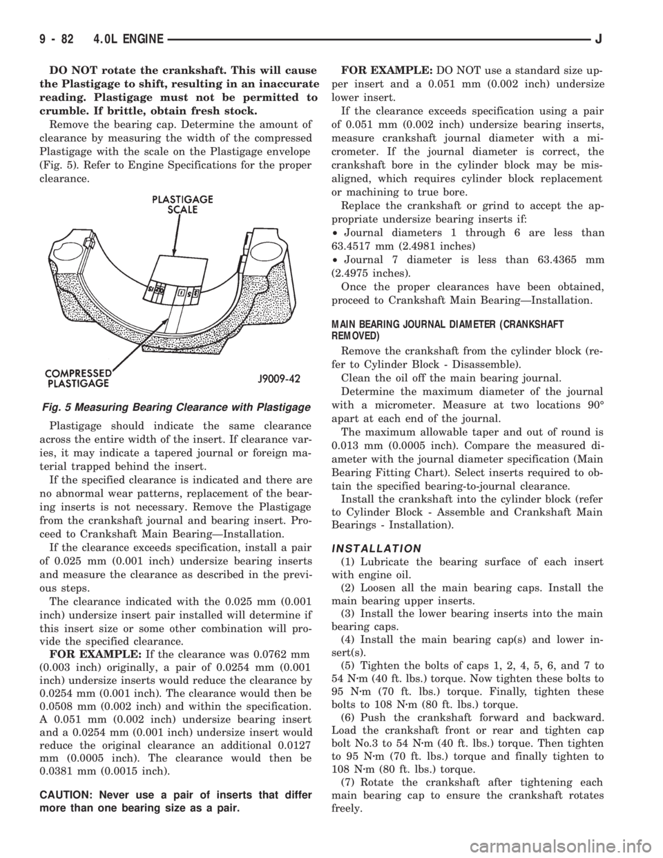
Remove the bearing cap. Determine the amount of
clearance by measuring the width of the compressed
Plastigage with the scale on the Plastigage envelope
(Fig. 5). Refer to Engine Specifications for the proper
clearance.
Plastigage should indicate the same clearance
across the entire width of the insert. If clearance var-
ies, it may indicate a tapered journal or foreign ma-
terial trapped behind the insert.
If the specified clearance is indicated and there are
no abnormal wear patterns, replacement of the bear-
ing inserts is not necessary. Remove the Plastigage
from the crankshaft journal and bearing insert. Pro-
ceed to Crankshaft Main BearingÐInstallation.
If the clearance exceeds specification, install a pair
of 0.025 mm (0.001 inch) undersize bearing inserts
and measure the clearance as described in the previ-
ous steps.
The clearance indicated with the 0.025 mm (0.001
inch) undersize insert pair installed will determine if
this insert size or some other combination will pro-
vide the specified clearance.
FOR EXAMPLE:If the clearance was 0.0762 mm
(0.003 inch) originally, a pair of 0.0254 mm (0.001
inch) undersize inserts would reduce the clearance by
0.0254 mm (0.001 inch). The clearance would then be
0.0508 mm (0.002 inch) and within the specification.
A 0.051 mm (0.002 inch) undersize bearing insert
and a 0.0254 mm (0.001 inch) undersize insert would
reduce the original clearance an additional 0.0127
mm (0.0005 inch). The clearance would then be
0.0381 mm (0.0015 inch).
CAUTION: Never use a pair of inserts that differ
more than one bearing size as a pair.FOR EXAMPLE:DO NOT use a standard size up-
per insert and a 0.051 mm (0.002 inch) undersize
lower insert.
If the clearance exceeds specification using a pair
of 0.051 mm (0.002 inch) undersize bearing inserts,
measure crankshaft journal diameter with a mi-
crometer. If the journal diameter is correct, the
crankshaft bore in the cylinder block may be mis-
aligned, which requires cylinder block replacement
or machining to true bore.
Replace the crankshaft or grind to accept the ap-
propriate undersize bearing inserts if:
²Journal diameters 1 through 6 are less than
63.4517 mm (2.4981 inches)
²Journal 7 diameter is less than 63.4365 mm
(2.4975 inches).
Once the proper clearances have been obtained,
proceed to Crankshaft Main BearingÐInstallation.
MAIN BEARING JOURNAL DIAMETER (CRANKSHAFT
REMOVED)
Remove the crankshaft from the cylinder block (re-
fer to Cylinder Block - Disassemble).
Clean the oil off the main bearing journal.
Determine the maximum diameter of the journal
with a micrometer. Measure at two locations 90É
apart at each end of the journal.
The maximum allowable taper and out of round is
0.013 mm (0.0005 inch). Compare the measured di-
ameter with the journal diameter specification (Main
Bearing Fitting Chart). Select inserts required to ob-
tain the specified bearing-to-journal clearance.
Install the crankshaft into the cylinder block (refer
to Cylinder Block - Assemble and Crankshaft Main
Bearings - Installation).
INSTALLATION
(1) Lubricate the bearing surface of each insert
with engine oil.
(2) Loosen all the main bearing caps. Install the
main bearing upper inserts.
(3) Install the lower bearing inserts into the main
bearing caps.
(4) Install the main bearing cap(s) and lower in-
sert(s).
(5) Tighten the bolts of caps 1, 2, 4, 5, 6, and 7 to
54 Nzm (40 ft. lbs.) torque. Now tighten these bolts to
95 Nzm (70 ft. lbs.) torque. Finally, tighten these
bolts to 108 Nzm (80 ft. lbs.) torque.
(6) Push the crankshaft forward and backward.
Load the crankshaft front or rear and tighten cap
bolt No.3 to 54 Nzm (40 ft. lbs.) torque. Then tighten
to 95 Nzm (70 ft. lbs.) torque and finally tighten to
108 Nzm (80 ft. lbs.) torque.
(7) Rotate the crankshaft after tightening each
main bearing cap to ensure the crankshaft rotates
freely.
Fig. 5 Measuring Bearing Clearance with Plastigage
9 - 82 4.0L ENGINEJ
Page 976 of 1784
INSTALLATIONÐYJ MODELS
(1) Place tank into skid plate. Wrap straps around
tank with strap bolts inserted through holes in skid
plate. Tighten strap nuts to 7.3 Nzm (65 in. lbs.) torque.
(2) Raise skid plate/fuel tank until gauge sender wire
connector can be connected to harness connector.
(3) Finish raising skid plate/fuel tank assembly
into position. Tighten mounting nuts to 16 Nzm (12
ft. lbs.) torque. Remove transmission jack.
(4) Connect fuel fill hose and fill vent hose to filler
neck. Tighten hose clamps.
(5) Connect vent hose to vent tube.
(6) Connect fuel supply hose to the supply tube and
fuel return hose to return tube. Tighten hose clamps.
(7) Install fuel filler neck shroud with push clips.
(8) Lower vehicle.
(9) Fill fuel tank. Install filler cap.
(10) Connect negative battery cable to battery.
(11) Start vehicle and inspect for leaks.
FUEL GAUGE SENDING UNIT
The fuel gauge sending unit is attached to the fuel
pump module. Refer to Fuel Pump Module in the
Fuel Delivery System section of this group.
FUEL TANK PRESSURE RELIEF/ROLLOVER VALVE
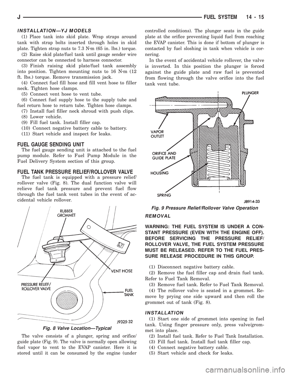
The fuel tank is equipped with a pressure relief/
rollover valve (Fig. 8). The dual function valve will
relieve fuel tank pressure and prevent fuel flow
through the fuel tank vent tubes in the event of ac-
cidental vehicle rollover.
The valve consists of a plunger, spring and orifice/
guide plate (Fig. 9). The valve is normally open allowing
fuel vapor to vent to the EVAP canister. Here it is
stored until it can be consumed by the engine (undercontrolled conditions). The plunger seats in the guide
plate at the orifice preventing liquid fuel from reaching
the EVAP canister. This is done if bottom of plunger is
contacted by fuel sloshing in tank when vehicle is cor-
nering.
In the event of accidental vehicle rollover, the valve
is inverted. In this position the plunger is forced
against the guide plate and raw fuel is prevented
from flowing through the valve orifice into the fuel
tank vent tube.
REMOVAL
WARNING: THE FUEL SYSTEM IS UNDER A CON-
STANT PRESSURE (EVEN WITH THE ENGINE OFF).
BEFORE SERVICING THE PRESSURE RELIEF/
ROLLOVER VALVE, THE FUEL SYSTEM PRESSURE
MUST BE RELEASED. REFER TO THE FUEL PRES-
SURE RELEASE PROCEDURE IN THIS GROUP.
(1) Disconnect negative battery cable.
(2) Remove the fuel filler cap and drain fuel tank.
Refer to Fuel Tank Removal.
(3) Remove fuel tank. Refer to Fuel Tank Removal.
(4) The rollover valve is seated in a grommet. Re-
move by prying one side upward and then roll the
grommet out of tank (Fig. 8).
INSTALLATION
(1) Start one side of grommet into opening in fuel
tank. Using finger pressure only, press valve/grom-
met into place.
(2) Install fuel tank. Refer to Fuel Tank Installation.
(3) Fill fuel tank. Install fuel tank filler cap.
(4) Connect negative battery cable.
(5) Start vehicle and check for leaks.
Fig. 8 Valve LocationÐTypical
Fig. 9 Pressure Relief/Rollover Valve Operation
JFUEL SYSTEM 14 - 15
Page 982 of 1784
Refer to Group 8D, Ignition System for more crank-
shaft position sensor information.
The engine will not operate if the PCM does not re-
ceive a crankshaft position sensor input.
ENGINE COOLANT TEMPERATURE SENSORÐPCM
INPUT
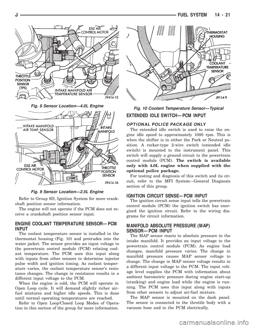
The coolant temperature sensor is installed in the
thermostat housing (Fig. 10) and protrudes into the
water jacket. The sensor provides an input voltage to
the powertrain control module (PCM) relating cool-
ant temperature. The PCM uses this input along
with inputs from other sensors to determine injector
pulse width and ignition timing. As coolant temper-
ature varies, the coolant temperature sensor's resis-
tance changes. The change in resistance results in a
different input voltage to the PCM.
When the engine is cold, the PCM will operate in
Open Loop cycle. It will demand slightly richer air-
fuel mixtures and higher idle speeds. This is done
until normal operating temperatures are reached.
Refer to Open Loop/Closed Loop Modes of Opera-
tion in this section of the group for more information.
EXTENDED IDLE SWITCHÐPCM INPUT
OPTIONAL POLICE PACKAGE ONLY
The extended idle switch is used to raise the en-
gine idle speed to approximately 1000 rpm. This is
when the shifter is in either the Park or Neutral po-
sition. A rocker-type 2-wire switch (extended idle
switch) is mounted to the instrument panel. This
switch will supply a ground circuit to the powertrain
control module (PCM).The switch is available
only with 4.0L engine when supplied with the
optional police package.
For testing and diagnosis of this switch and its cir-
cuit, refer to the MFI SystemÐGeneral Diagnosis
section of this group.
IGNITION CIRCUIT SENSEÐPCM INPUT
The ignition circuit sense input tells the powertrain
control module (PCM) the ignition switch has ener-
gized the ignition circuit. Refer to the wiring dia-
grams for circuit information.
MANIFOLD ABSOLUTE PRESSURE (MAP)
SENSORÐPCM INPUT
The MAP sensor reacts to absolute pressure in the
intake manifold. It provides an input voltage to the
powertrain control module (PCM). As engine load
changes, manifold pressure varies. The change in
manifold pressure causes MAP sensor voltage to
change. The change in MAP sensor voltage results in
a different input voltage to the PCM. The input volt-
age level supplies the PCM with information about
ambient barometric pressure during engine start-up
(cranking) and engine load while the engine is run-
ning. The PCM uses this input along with inputs
from other sensors to adjust air-fuel mixture.
The MAP sensor is mounted on the dash panel.
The sensor is connected to the throttle body with a
vacuum hose and to the PCM electrically.
Fig. 8 Sensor LocationÐ4.0L Engine
Fig. 9 Sensor LocationÐ2.5L Engine
Fig. 10 Coolant Temperature SensorÐTypical
JFUEL SYSTEM 14 - 21
Page 983 of 1784
OVERDRIVE/OVERRIDE SWITCH
On vehicles equipped with overdrive, the power-
train control module (PCM) regulates the 3-4 over-
drive up-shift and down-shift through the overdrive
solenoid.
Refer to Group 21 for more information.
OXYGEN (O2S) SENSORÐPCM INPUT
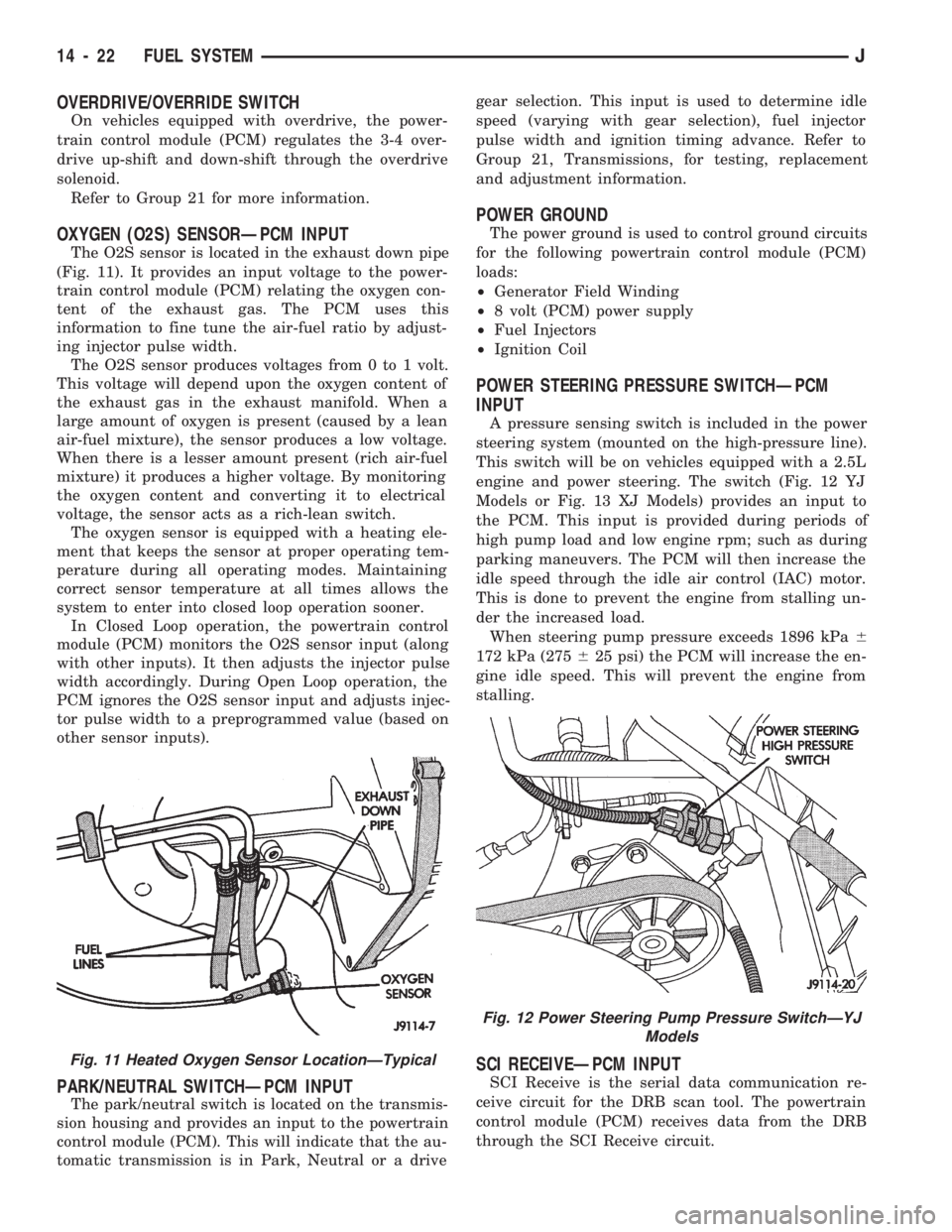
The O2S sensor is located in the exhaust down pipe
(Fig. 11). It provides an input voltage to the power-
train control module (PCM) relating the oxygen con-
tent of the exhaust gas. The PCM uses this
information to fine tune the air-fuel ratio by adjust-
ing injector pulse width.
The O2S sensor produces voltages from 0 to 1 volt.
This voltage will depend upon the oxygen content of
the exhaust gas in the exhaust manifold. When a
large amount of oxygen is present (caused by a lean
air-fuel mixture), the sensor produces a low voltage.
When there is a lesser amount present (rich air-fuel
mixture) it produces a higher voltage. By monitoring
the oxygen content and converting it to electrical
voltage, the sensor acts as a rich-lean switch.
The oxygen sensor is equipped with a heating ele-
ment that keeps the sensor at proper operating tem-
perature during all operating modes. Maintaining
correct sensor temperature at all times allows the
system to enter into closed loop operation sooner.
In Closed Loop operation, the powertrain control
module (PCM) monitors the O2S sensor input (along
with other inputs). It then adjusts the injector pulse
width accordingly. During Open Loop operation, the
PCM ignores the O2S sensor input and adjusts injec-
tor pulse width to a preprogrammed value (based on
other sensor inputs).
PARK/NEUTRAL SWITCHÐPCM INPUT
The park/neutral switch is located on the transmis-
sion housing and provides an input to the powertrain
control module (PCM). This will indicate that the au-
tomatic transmission is in Park, Neutral or a drivegear selection. This input is used to determine idle
speed (varying with gear selection), fuel injector
pulse width and ignition timing advance. Refer to
Group 21, Transmissions, for testing, replacement
and adjustment information.
POWER GROUND
The power ground is used to control ground circuits
for the following powertrain control module (PCM)
loads:
²Generator Field Winding
²8 volt (PCM) power supply
²Fuel Injectors
²Ignition Coil
POWER STEERING PRESSURE SWITCHÐPCM
INPUT
A pressure sensing switch is included in the power
steering system (mounted on the high-pressure line).
This switch will be on vehicles equipped with a 2.5L
engine and power steering. The switch (Fig. 12 YJ
Models or Fig. 13 XJ Models) provides an input to
the PCM. This input is provided during periods of
high pump load and low engine rpm; such as during
parking maneuvers. The PCM will then increase the
idle speed through the idle air control (IAC) motor.
This is done to prevent the engine from stalling un-
der the increased load.
When steering pump pressure exceeds 1896 kPa6
172 kPa (275625 psi) the PCM will increase the en-
gine idle speed. This will prevent the engine from
stalling.
SCI RECEIVEÐPCM INPUT
SCI Receive is the serial data communication re-
ceive circuit for the DRB scan tool. The powertrain
control module (PCM) receives data from the DRB
through the SCI Receive circuit.
Fig. 11 Heated Oxygen Sensor LocationÐTypical
Fig. 12 Power Steering Pump Pressure SwitchÐYJ
Models
14 - 22 FUEL SYSTEMJ
Page 988 of 1784
SPEED CONTROLÐPCM OUTPUT
Speed control operation is regulated by the power-
train control module (PCM). The PCM controls the
vacuum to the throttle actuator through the speed
control vacuum and vent solenoids. Refer to Group
8H for speed control information.
TACHOMETERÐPCM OUTPUT
The powertrain control module (PCM) supplies en-
gine rpm values to the instrument cluster tachome-
ter (if equipped). Refer to Group 8E for tachometer
information.
TORQUE CONVERTER CLUTCH RELAYÐPCM
OUTPUT
ALL 2.5L 4 CYL. WITH 3-SPEED AUTO. TRANS
4.0L 6 CYL. YJ MODELS WITH 3-SPEED AUTO.
TRANS
The transmission mounted torque converter clutch
(TCC) solenoid is used to control the torque con-
verter. The solenoid is controlled through the power-
train control module (PCM) and by the TCC relay.
This relay is used only on vehicles equipped with a
3-speed automatic transmission.
An electrical output signal is sent from the PCM to
the TCC relay after the PCM receives information
from the vehicle speed, MAP, throttle position and
engine coolant temperature sensors. After the TCC
relay receives this necessary information, it will send
a signal to the torque converter clutch solenoid to
control the torque converter.
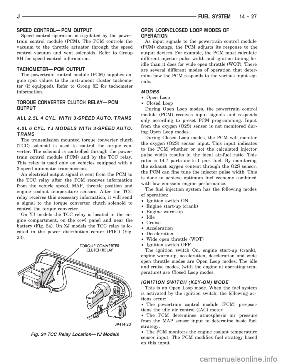
On YJ models the TCC relay is located in the en-
gine compartment, on the cowl panel and near the
battery (Fig. 24). On XJ models the TCC relay is lo-
cated in the power distribution center (PDC) (Fig.
23).
OPEN LOOP/CLOSED LOOP MODES OF
OPERATION
As input signals to the powertrain control module
(PCM) change, the PCM adjusts its response to the
output devices. For example, the PCM must calculate
different injector pulse width and ignition timing for
idle than it does for wide open throttle (WOT). There
are several different modes of operation that deter-
mine how the PCM responds to the various input sig-
nals.
MODES
²Open Loop
²Closed Loop
During Open Loop modes, the powertrain control
module (PCM) receives input signals and responds
only according to preset PCM programming. Input
from the oxygen (O2S) sensor is not monitored dur-
ing Open Loop modes.
During Closed Loop modes, the PCM will monitor
the oxygen (O2S) sensor input. This input indicates
to the PCM whether or not the calculated injector
pulse width results in the ideal air-fuel ratio. This
ratio is 14.7 parts air-to-1 part fuel. By monitoring
the exhaust oxygen content through the O2S sensor,
the PCM can fine tune the injector pulse width. This
is done to achieve optimum fuel economy combined
with low emission engine performance.
The fuel injection system has the following modes
of operation:
²Ignition switch ON
²Engine start-up (crank)
²Engine warm-up
²Idle
²Cruise
²Acceleration
²Deceleration
²Wide open throttle (WOT)
²Ignition switch OFF
The ignition switch On, engine start-up (crank),
engine warm-up, acceleration, deceleration and wide
open throttle modes are Open Loop modes. The idle
and cruise modes, (with the engine at operating tem-
perature) are Closed Loop modes.
IGNITION SWITCH (KEY-ON) MODE
This is an Open Loop mode. When the fuel system
is activated by the ignition switch, the following ac-
tions occur:
²The powertrain control module (PCM) pre-posi-
tions the idle air control (IAC) motor.
²The PCM determines atmospheric air pressure
from the MAP sensor input to determine basic fuel
strategy.
²The PCM monitors the engine coolant temperature
sensor input. The PCM modifies fuel strategy based
on this input.
Fig. 24 TCC Relay LocationÐYJ Models
JFUEL SYSTEM 14 - 27
Page 1017 of 1784
INSTALLATION
(1) Install the fuel injector(s) into the fuel rail as-
sembly and install retaining clip(s).
(2) Install fuel rail. Refer to Fuel Rail Installation
in this section.
(3) Start engine and check for fuel leaks.
FUEL PUMP MODULE
Refer to the Fuel Delivery System section of this
group for removal/installation procedures.
FUEL PUMP RELAY
The Fuel Pump relay is located in the Power Dis-
tribution Center (PDC) (Figs. 1 or 2). For location of
this relay within the PDC, refer to label on PDC
cover.
FUEL RAIL ASSEMBLY
REMOVAL
WARNING: THE FUEL SYSTEM IS UNDER CON-
STANT FUEL PRESSURE (EVEN WITH THE ENGINE
OFF) OF APPROXIMATELY 131-269 KPA (19-39
PSI). THIS PRESSURE MUST BE RELEASED BE-
FORE SERVICING THE FUEL RAIL.
(1) Remove fuel tank filler tube cap.
(2) Disconnect the negative battery cable from bat-
tery.
(3) Perform the Fuel System Pressure Release Pro-
cedure as described in the Fuel Delivery System sec-
tion of this Group.
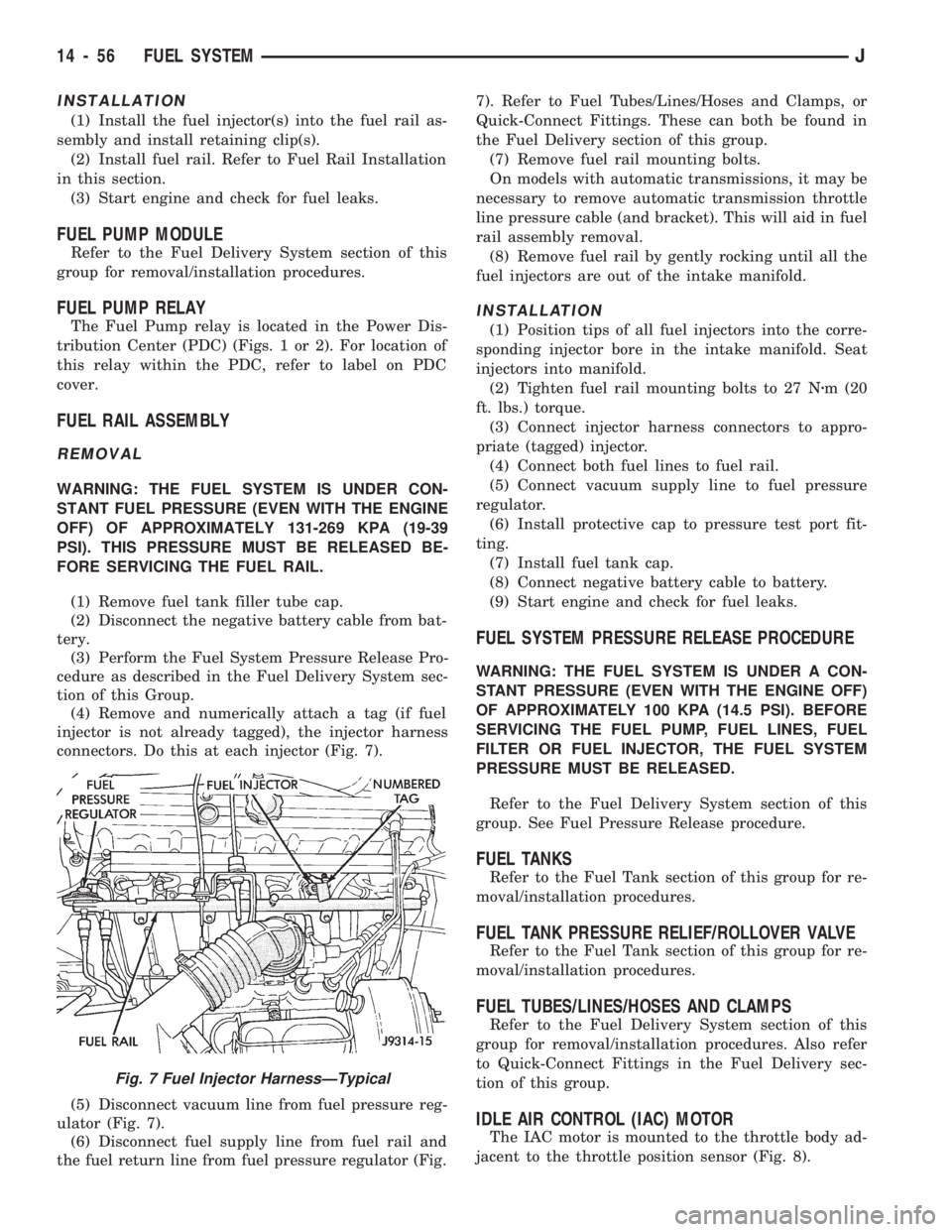
(4) Remove and numerically attach a tag (if fuel
injector is not already tagged), the injector harness
connectors. Do this at each injector (Fig. 7).
(5) Disconnect vacuum line from fuel pressure reg-
ulator (Fig. 7).
(6) Disconnect fuel supply line from fuel rail and
the fuel return line from fuel pressure regulator (Fig.7). Refer to Fuel Tubes/Lines/Hoses and Clamps, or
Quick-Connect Fittings. These can both be found in
the Fuel Delivery section of this group.
(7) Remove fuel rail mounting bolts.
On models with automatic transmissions, it may be
necessary to remove automatic transmission throttle
line pressure cable (and bracket). This will aid in fuel
rail assembly removal.
(8) Remove fuel rail by gently rocking until all the
fuel injectors are out of the intake manifold.
INSTALLATION
(1) Position tips of all fuel injectors into the corre-
sponding injector bore in the intake manifold. Seat
injectors into manifold.
(2) Tighten fuel rail mounting bolts to 27 Nzm (20
ft. lbs.) torque.
(3) Connect injector harness connectors to appro-
priate (tagged) injector.
(4) Connect both fuel lines to fuel rail.
(5) Connect vacuum supply line to fuel pressure
regulator.
(6) Install protective cap to pressure test port fit-
ting.
(7) Install fuel tank cap.
(8) Connect negative battery cable to battery.
(9) Start engine and check for fuel leaks.
FUEL SYSTEM PRESSURE RELEASE PROCEDURE
WARNING: THE FUEL SYSTEM IS UNDER A CON-
STANT PRESSURE (EVEN WITH THE ENGINE OFF)
OF APPROXIMATELY 100 KPA (14.5 PSI). BEFORE
SERVICING THE FUEL PUMP, FUEL LINES, FUEL
FILTER OR FUEL INJECTOR, THE FUEL SYSTEM
PRESSURE MUST BE RELEASED.
Refer to the Fuel Delivery System section of this
group. See Fuel Pressure Release procedure.
FUEL TANKS
Refer to the Fuel Tank section of this group for re-
moval/installation procedures.
FUEL TANK PRESSURE RELIEF/ROLLOVER VALVE
Refer to the Fuel Tank section of this group for re-
moval/installation procedures.
FUEL TUBES/LINES/HOSES AND CLAMPS
Refer to the Fuel Delivery System section of this
group for removal/installation procedures. Also refer
to Quick-Connect Fittings in the Fuel Delivery sec-
tion of this group.
IDLE AIR CONTROL (IAC) MOTOR
The IAC motor is mounted to the throttle body ad-
jacent to the throttle position sensor (Fig. 8).
Fig. 7 Fuel Injector HarnessÐTypical
14 - 56 FUEL SYSTEMJ