1994 JEEP CHEROKEE Engine mount location
[x] Cancel search: Engine mount locationPage 842 of 1784
ENGINES
CONTENTS
page page
2.5L ENGINE SERVICE PROCEDURES....... 9
4.0L ENGINE SERVICE PROCEDURES...... 50ENGINE DIAGNOSIS...................... 5
STANDARD SERVICE PROCEDURES......... 1
STANDARD SERVICE PROCEDURES
INDEX
page page
Engine Performance....................... 2
Form-In-Place Gaskets..................... 1
Honing Cylinder Bores..................... 2
Hydrostatic Lock.......................... 4Measuring with Plastigage................... 3
Repair Damaged or Worn Threads............ 4
Service Engine Assembly (Short Block)......... 4
FORM-IN-PLACE GASKETS
There are several places where form-in-place gas-
kets are used on the engine.DO NOT use form-in-
place gasket material unless specified.Care must
be taken when applying form-in-place gaskets. Bead
size, continuity and location are of great importance.
Too thin a bead can result in leakage while too much
can result in spill-over. A continuous bead of the
proper width is essential to obtain a leak-free joint.
Two types of form-in-place gasket materials are
used in the engine area (Mopar Silicone Rubber Ad-
hesive Sealant and Mopar Gasket Maker). Each have
different properties and cannot be used interchange-
ably.
MOPAR SILICONE RUBBER ADHESIVE
SEALANT
Mopar Silicone Rubber Adhesive Sealant, normally
black in color, is available in 3 ounce tubes. Moisture
in the air causes the sealant material to cure. This
material is normally used on flexible metal flanges.
It has a shelf life of a year and will not properly cure
if over aged. Always inspect the package for the ex-
piration date before use.
MOPAR GASKET MAKER
Mopar Gasket Maker, normally red in color, is
available in 6 cc tubes. This anaerobic type gasket
material cures in the absence of air when squeezed
between smooth machined metallic surfaces. It will
not cure if left in the uncovered tube. DO NOT use
on flexible metal flanges.
SURFACE PREPARATION
Parts assembled with form-in-place gaskets may be
disassembled without unusual effort. In some in-
stances, it may be necessary to lightly tap the part
with a mallet or other suitable tool to break the seal
between the mating surfaces. A flat gasket scraper
may also be lightly tapped into the joint but care
must be taken not to damage the mating surfaces.
Scrape or wire brush all gasket surfaces to remove
all loose material. Inspect stamped parts to ensure
gasket rails are flat. Flatten rails with a hammer on
a flat plate, if required. Gasket surfaces must be free
of oil and dirt. Make sure the old gasket material is
removed from blind attaching holes.
GASKET APPLICATION
Assembling parts using a form-in-place gasket re-
quires care.
Mopar Silicone Rubber Adhesive Sealant should be
applied in a continuous bead approximately 3 mm
(0.12 inch) in diameter. All mounting holes must be
circled. For corner sealing,a3or6mm(1/8 or 1/4
inch) drop is placed in the center of the gasket con-
tact area. Uncured sealant may be removed with a
shop towel. Components should be torqued in place
while the sealant is still wet to the touch (within 10
minutes). The use of a locating dowel is recom-
mended during assembly to prevent smearing the
material off location.
Mopar Gasket Maker should be applied sparingly
to one gasket surface. The sealant diameter should
be 1.00 mm (0.04 inch) or less. Be certain the mate-
rial surrounds each mounting hole. Excess material
JENGINES 9 - 1
Page 850 of 1784
2.5L ENGINE SERVICE PROCEDURES
INDEX
page page
Camshaft............................... 29
Camshaft Pin Replacement................. 31
Crankshaft Main Bearings.................. 40
Cylinder Block........................... 45
Engine AssemblyÐXJ Vehicles.............. 14
Engine AssemblyÐYJ Vehicles.............. 16
Engine Cylinder Head..................... 19
Engine Cylinder Head Cover................ 18
Engine Damper.......................... 13
Engine MountÐRear...................... 12
Engine MountsÐFront..................... 10
General Information........................ 9
Hydraulic Tappets........................ 24Oil Pan ................................ 32
Oil Pump............................... 33
Pistons and Connecting Rods............... 34
Rear Main Oil Seals...................... 44
Rocker Arms............................ 19
Specifications........................... 47
Timing Case Cover....................... 27
Timing Case Cover Oil Seal Replacement...... 26
Timing Chain and Sprockets................ 28
Valve Springs and Oil Seals................ 21
Valve Timing............................ 26
Valves and Valve Springs.................. 22
Vibration Damper........................ 26
GENERAL INFORMATION
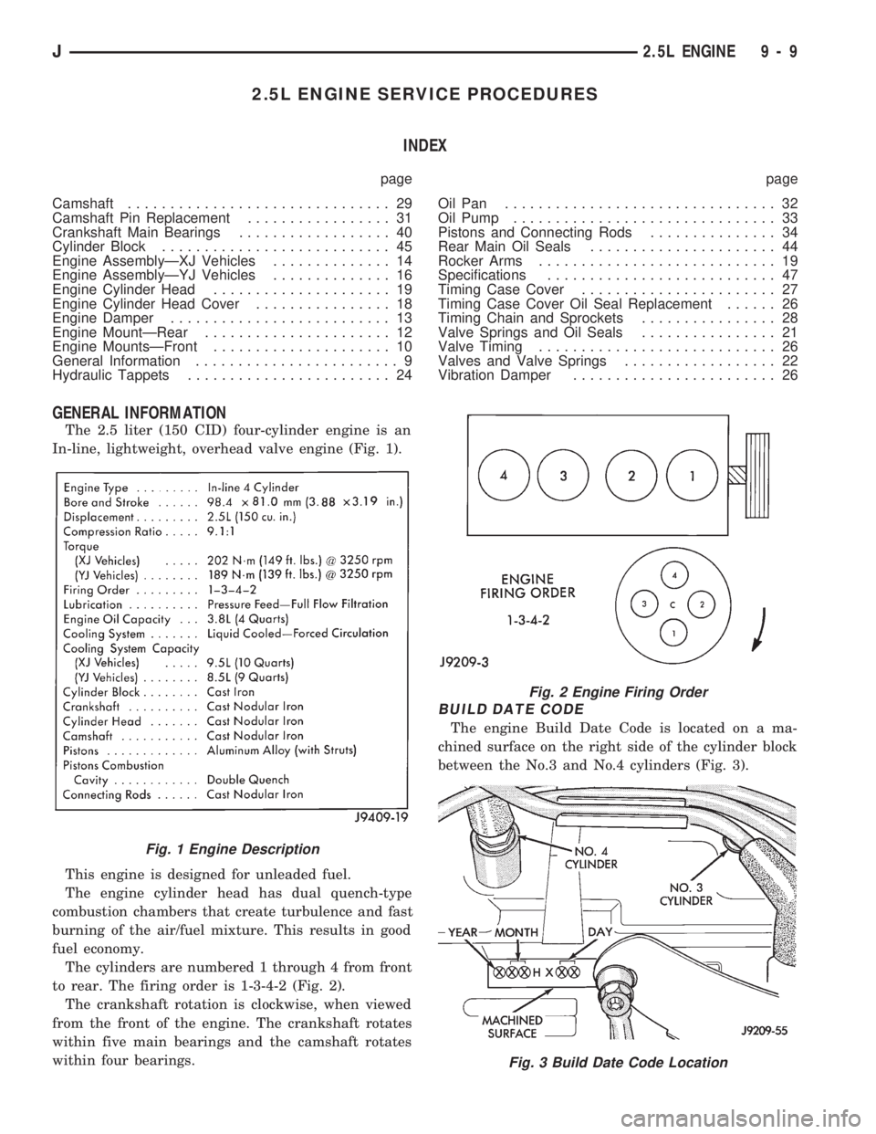
The 2.5 liter (150 CID) four-cylinder engine is an
In-line, lightweight, overhead valve engine (Fig. 1).
This engine is designed for unleaded fuel.
The engine cylinder head has dual quench-type
combustion chambers that create turbulence and fast
burning of the air/fuel mixture. This results in good
fuel economy.
The cylinders are numbered 1 through 4 from front
to rear. The firing order is 1-3-4-2 (Fig. 2).
The crankshaft rotation is clockwise, when viewed
from the front of the engine. The crankshaft rotates
within five main bearings and the camshaft rotates
within four bearings.
BUILD DATE CODE
The engine Build Date Code is located on a ma-
chined surface on the right side of the cylinder block
between the No.3 and No.4 cylinders (Fig. 3).
Fig. 1 Engine Description
Fig. 2 Engine Firing Order
Fig. 3 Build Date Code Location
J2.5L ENGINE 9 - 9
Page 851 of 1784

The digits of the code identify:
(1) 1st DigitÐThe year (4 = 1994).
(2) 2nd & 3rd DigitsÐThe month (01 - 12).
(3) 4th & 5th DigitsÐThe engine type/fuel system/
compression ratio (HX = A 2.5 liter (150 CID) 9.1:1
compression ratio engine with a multi-point fuel in-
jection system).
(4) 6th & 7th DigitsÐThe day of engine build (01 -
31).
FOR EXAMPLE:Code * 401HX23 * identifies a
2.5 liter (150 CID) engine with a multi-point fuel in-
jection system, 9.1:1 compression ratio and built on
January 23, 1994.
OVERSIZE AND UNDERSIZE COMPONENT
CODES
Some engines may be built with oversize or under-
size components such as:
²Oversize cylinder bores.
²Oversize camshaft bearing bores.
²Undersize crankshaft main bearing journals.
²Undersize connecting rod journals.
These engines are identified by a letter code (Fig.
4) stamped on the oil filter boss near the distributor
(Fig. 5).
ENGINE MOUNTSÐFRONT
The front mounts support the engine at each side.
These supports are made of resilient rubber.
REMOVALÐXJ VEHICLES
(1) Disconnect negative cable from battery.
(2) Raise the vehicle.
(3) Support the engine.
(4) Remove through bolt nut (Fig. 6). DO NOT re-
move the through bolt.
(5) Remove the retaining bolts/nuts from the sup-
port cushions (Fig. 6).
(6) Remove the through bolt.
(7) Remove the support cushions.
INSTALLATIONÐXJ VEHICLES
(1) If the engine support bracket was removed, po-
sition the LEFT bracket (Fig. 6) and the RIGHT
bracket with generator brace (Fig. 7) onto the cylin-
der block. Install the bolts and stud nuts.
(a) RIGHT SIDE (Fig. 7)ÐTighten the bolts to
61 Nzm (45 ft. lbs.) torque. Tighten the stud nuts to
46 Nzm (34 ft. lbs.) torque.
(b) LEFT SIDE (Fig. 6)ÐTighten the bolts to 61
Nzm (45 ft. lbs.) torque.
(2) If the support cushion brackets were removed,
position the brackets onto the lower front sill (Figs. 6
and 8). Install the bolts and stud nuts. Tighten the
bolts to 54 Nzm (40 ft. lbs.) torque and the stud nuts
to 41 Nzm (30 ft. lbs.) torque.
(3) Place the support cushions onto the support
cushion brackets (Fig. 6). Tighten the right support
cushion nuts to 65 Nzm (48 ft. lbs.) torque. Tighten
the left support cushion bolt/nut to 41 Nzm (30 ft.
lbs.) torque.
Fig. 4 Oversize and Undersize Component Codes
Fig. 5 Oversize and Undersize Component Code
Location
9 - 10 2.5L ENGINEJ
Page 861 of 1784

(a) Remove the bolts from the A/C compressor
mounting bracket and set the compressor aside.
(b) Remove the air conditioner compressor
bracket bolts from the engine cylinder head.
(c) Loosen the through bolt at the bottom of the
bracket.
(9) If equipped, disconnect the power steering
pump bracket. Set the pump and bracket aside. DO
NOT disconnect the hoses.
(10) Remove the fuel lines and vacuum advance
hose.
(11) Remove the intake and engine exhaust mani-
folds from the engine cylinder head (refer to Group
11, Exhaust System and Intake Manifold for the
proper procedures).
(12) Disconnect the ignition wires and remove the
spark plugs.
(13) Disconnect the temperature sending unit wire
connector.
(14) Remove the ignition coil and bracket assem-
bly.
(15) Remove the engine cylinder head bolts.
(16) Remove the engine cylinder head and gasket
(Fig. 3).
(17) If this was the first time the bolts were re-
moved, put a paint dab on the top of the bolt. If the
bolts have a paint dab on the top of the bolt or it
isn't known if they were used before, discard the
bolts.
(18) Stuff clean lint free shop towels into the cyl-
inder bores.
CLEANING
Thoroughly clean the engine cylinder head and cyl-
inder block mating surfaces. Clean the intake and
exhaust manifold and engine cylinder head mating
surfaces. Remove all gasket material and carbon.
Check to ensure that no coolant or foreign material
has fallen into the tappet bore area.
Remove the carbon deposits from the combustion
chambers and top of the pistons.
INSPECTION
Use a straightedge and feeler gauge to check the
flatness of the engine cylinder head and block mat-
ing surfaces.
INSTALLATION
The engine cylinder head gasket is a composition
gasket. The gasket is to be installed DRY.DO NOT
use a gasket sealing compound on the gasket.
If the engine cylinder head is to be replaced and
the original valves used, measure the valve stem di-
ameter. Only standard size valves can be used with a
service replacement engine cylinder head unless the
replacement head valve stem guide bores are reamed
to accommodate oversize valve stems. Remove all
carbon buildup and reface the valves.
(1) Fabricate two engine cylinder head alignment
dowels from used head bolts (Fig. 4). Use the longest
head bolt. Cut the head of the bolt off below the hex
head. Then cut a slot in the top of the dowel to allow
easier removal with a screwdriver.
(2) Install one dowel in bolt hole No.10 and the
other dowel in bolt hole No.8 (Fig. 5).
(3) Remove the shop towels from the cylinder
bores. Coat the bores with clean engine oil.
(4) Place the engine cylinder head gasket (with the
numbers facing up) over the dowels.
Fig. 3 Engine Cylinder Head Assembly
Fig. 4 Fabricate Alignment Dowels
Fig. 5 Alignment Dowel Locations
9 - 20 2.5L ENGINEJ
Page 883 of 1784
BEARING-TO-JOURNAL CLEARANCE (CRANKSHAFT
INSTALLED)
When using Plastigage, check only one bearing
clearance at a time.
Install the grooved main bearings into the cylinder
block and the non-grooved bearings into the bearing
caps.
Install the crankshaft into the upper bearings dry.
Place a strip of Plastigage across full width of the
crankshaft journal to be checked.
Install the bearing cap and tighten the bolts to 108
Nzm (80 ft. lbs.) torque.
DO NOT rotate the crankshaft. This will cause
the Plastigage to shift, resulting in an inaccurate
reading. Plastigage must not be permitted to
crumble. If brittle, obtain fresh stock.
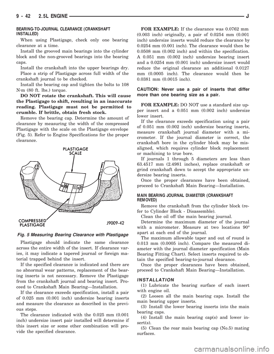
Remove the bearing cap. Determine the amount of
clearance by measuring the width of the compressed
Plastigage with the scale on the Plastigage envelope
(Fig. 5). Refer to Engine Specifications for the proper
clearance.
Plastigage should indicate the same clearance
across the entire width of the insert. If clearance var-
ies, it may indicate a tapered journal or foreign ma-
terial trapped behind the insert.
If the specified clearance is indicated and there are
no abnormal wear patterns, replacement of the bear-
ing inserts is not necessary. Remove the Plastigage
from the crankshaft journal and bearing insert. Pro-
ceed to Crankshaft Main BearingÐInstallation.
If the clearance exceeds specification, install a pair
of 0.025 mm (0.001 inch) undersize bearing inserts
and measure the clearance as described in the previ-
ous steps.
The clearance indicated with the 0.025 mm (0.001
inch) undersize insert pair installed will determine if
this insert size or some other combination will pro-
vide the specified clearance.FOR EXAMPLE:If the clearance was 0.0762 mm
(0.003 inch) originally, a pair of 0.0254 mm (0.001
inch) undersize inserts would reduce the clearance by
0.0254 mm (0.001 inch). The clearance would then be
0.0508 mm (0.002 inch) and within the specification.
A 0.051 mm (0.002 inch) undersize bearing insert
and a 0.0254 mm (0.001 inch) undersize insert would
reduce the original clearance an additional 0.0127
mm (0.0005 inch). The clearance would then be
0.0381 mm (0.0015 inch).
CAUTION: Never use a pair of inserts that differ
more than one bearing size as a pair.
FOR EXAMPLE:DO NOT use a standard size up-
per insert and a 0.051 mm (0.002 inch) undersize
lower insert.
If the clearance exceeds specification using a pair
of 0.051 mm (0.002 inch) undersize bearing inserts,
measure crankshaft journal diameter with a mi-
crometer. If the journal diameter is correct, the
crankshaft bore in the cylinder block may be mis-
aligned, which requires cylinder block replacement
or machining to true bore.
If journals 1 through 5 diameters are less than
63.4517 mm (2.4981 inches), replace crankshaft or
grind crankshaft down to accept the appropriate un-
dersize bearing inserts.
Once the proper clearances have been obtained,
proceed to Crankshaft Main BearingÐInstallation.
MAIN BEARING JOURNAL DIAMETER (CRANKSHAFT
REMOVED)
Remove the crankshaft from the cylinder block (re-
fer to Cylinder Block - Disassemble).
Clean the oil off the main bearing journal.
Determine the maximum diameter of the journal
with a micrometer. Measure at two locations 90É
apart at each end of the journal.
The maximum allowable taper and out of round is
0.013 mm (0.0005 inch). Compare the measured di-
ameter with the journal diameter specification (Main
Bearing Fitting Chart). Select inserts required to ob-
tain the specified bearing-to-journal clearance.
Once the proper clearances have been obtained,
proceed to Crankshaft Main BearingÐInstallation.
INSTALLATION
(1) Lubricate the bearing surface of each insert
with engine oil.
(2) Loosen all the main bearing caps. Install the
main bearing upper inserts.
(3) Install the lower bearing inserts into the main
bearing caps.
(4) Install the main bearing cap(s) and lower in-
sert(s).
(5) Clean the rear main bearing cap (No.5) mating
surfaces.
Fig. 5 Measuring Bearing Clearance with Plastigage
9 - 42 2.5L ENGINEJ
Page 885 of 1784

(6) Apply Loctite 515, or equivalent on the rear
bearing cap (Fig. 6). The bead should be 3 mm (0.125
in) thick. DO NOT apply Loctite 515, or equivalent
to the lip of the seal.
(7) Install the rear main bearing cap. DO NOT
strike the cap more than twice for proper engage-
ment.
(8) Tighten the bolts of caps 1, 3, 4 and 5 to 54
Nzm (40 ft. lbs.) torque. Now tighten these bolts to 95
Nzm (70 ft. lbs.) torque. Finally, tighten these bolts
to 108 Nzm (80 ft. lbs.) torque.
(9) Push the crankshaft forward and backward.
Load the crankshaft front or rear and tighten cap
bolt No.2 to 54 Nzm (40 ft. lbs.) torque. Then tighten
to 95 Nzm (70 ft. lbs.) torque and finally tighten to
108 Nzm (80 ft. lbs.) torque.
(10) Rotate the crankshaft after tightening each
main bearing cap to ensure the crankshaft rotates
freely.
(11) Check crankshaft end play. Crankshaft end
play is controlled by the thrust bearing which is
flange and installed at the No.2 main bearing posi-
tion.
(a) Attach a magnetic base dial indicator to the
cylinder block at either the front or rear of the en-
gine.
(b) Position the dial indicator rod so that it is
parallel to the center line of the crankshaft.
(c) Pry the crankshaft forward, position the dial
indicator to zero.
(d) Pry the crankshaft forward and backward.
Note the dial indicator readings. End play is the
difference between the high and low measurements
(Fig. 7). Correct end play is 0.038-0.165 mm(0.0015-0.0065 inch). The desired specifications are
0.051-0.064 mm (0.002-0.0025 inch).
(e) If end play is not within specification, inspect
crankshaft thrust faces for wear. If no wear is ap-
parent, replace the thrust bearing and measure end
play. If end play is still not within specification, re-
place the crankshaft.
If the crankshaft was removed, install the crank-
shaft into the cylinder block (refer to Cylinder Block -
Assemble).
(12) Install the oil pan.
(13) Install the drain plug. Tighten the plug to 34
Nzm (25 ft. lbs.) torque.
(14) Lower the vehicle.
(15) Install the spark plugs. Tighten the plugs to
37 Nzm (27 ft. lbs.) torque.
(16) Fill the oil pan with engine oil to the full
mark on the dipstick level.
(17) Connect negative cable to battery.
REAR MAIN OIL SEALS
REMOVAL
(1) Remove the flywheel or converter drive plate.
Discard the old bolts.
(2) Pry out the seal from around the crankshaft
flange (Fig. 8).
INSTALLATION
(1) Coat the outer lip of the replacement rear main
bearing seal with engine oil.
(2) Carefully position the seal into place. Use rear
main Seal Installer Tool 6271 to install the seal flush
with the cylinder block.
CAUTION: The felt lip must be located inside the
flywheel mounting surface. If the lip is not posi-
tioned correctly the flywheel could tear the seal.
Fig. 6 Location of Loctite 515 (or equivalent)
Fig. 7 Crankshaft End Play Measurement
9 - 44 2.5L ENGINEJ
Page 892 of 1784
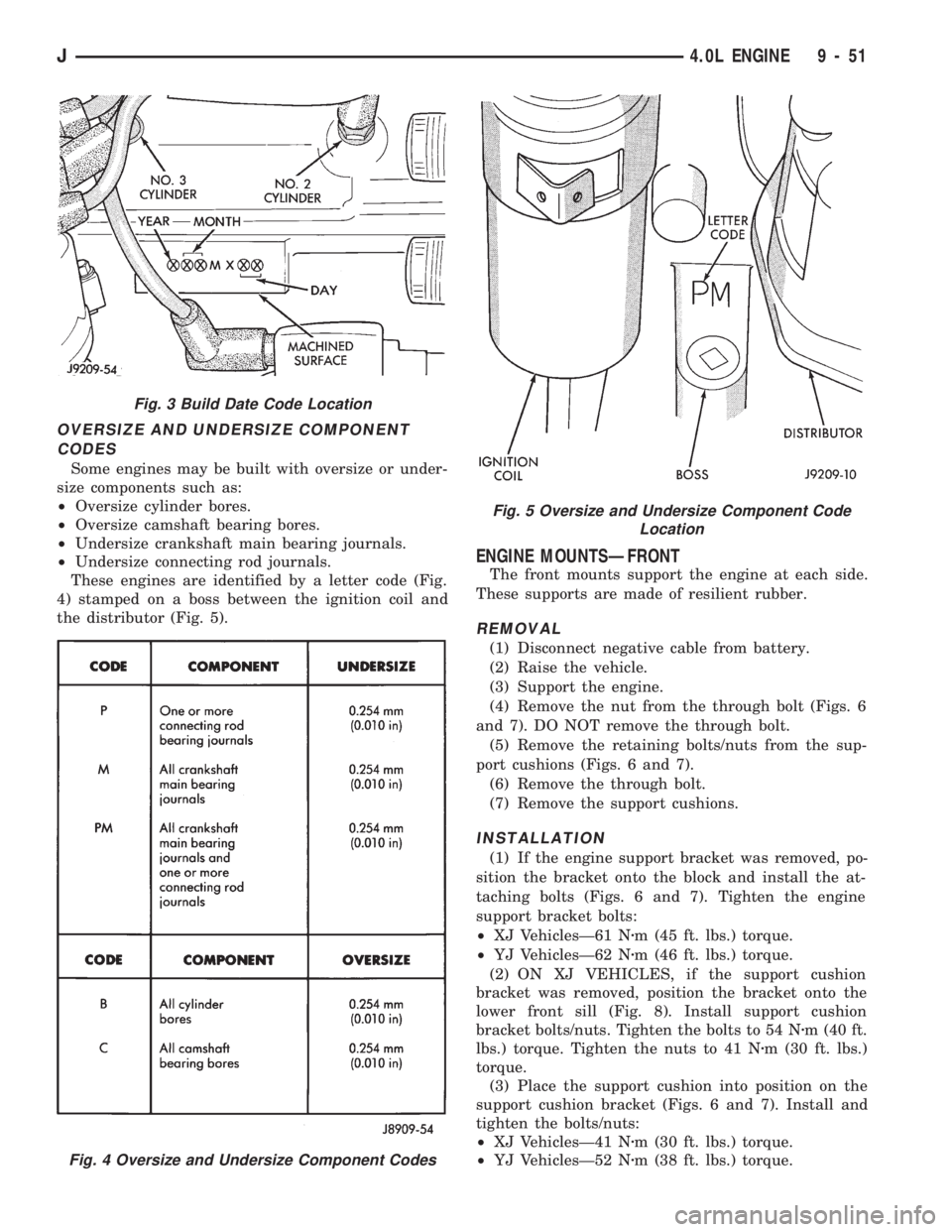
OVERSIZE AND UNDERSIZE COMPONENT
CODES
Some engines may be built with oversize or under-
size components such as:
²Oversize cylinder bores.
²Oversize camshaft bearing bores.
²Undersize crankshaft main bearing journals.
²Undersize connecting rod journals.
These engines are identified by a letter code (Fig.
4) stamped on a boss between the ignition coil and
the distributor (Fig. 5).
ENGINE MOUNTSÐFRONT
The front mounts support the engine at each side.
These supports are made of resilient rubber.
REMOVAL
(1) Disconnect negative cable from battery.
(2) Raise the vehicle.
(3) Support the engine.
(4) Remove the nut from the through bolt (Figs. 6
and 7). DO NOT remove the through bolt.
(5) Remove the retaining bolts/nuts from the sup-
port cushions (Figs. 6 and 7).
(6) Remove the through bolt.
(7) Remove the support cushions.
INSTALLATION
(1) If the engine support bracket was removed, po-
sition the bracket onto the block and install the at-
taching bolts (Figs. 6 and 7). Tighten the engine
support bracket bolts:
²XJ VehiclesÐ61 Nzm (45 ft. lbs.) torque.
²YJ VehiclesÐ62 Nzm (46 ft. lbs.) torque.
(2) ON XJ VEHICLES, if the support cushion
bracket was removed, position the bracket onto the
lower front sill (Fig. 8). Install support cushion
bracket bolts/nuts. Tighten the bolts to 54 Nzm (40 ft.
lbs.) torque. Tighten the nuts to 41 Nzm (30 ft. lbs.)
torque.
(3) Place the support cushion into position on the
support cushion bracket (Figs. 6 and 7). Install and
tighten the bolts/nuts:
²XJ VehiclesÐ41 Nzm (30 ft. lbs.) torque.
²YJ VehiclesÐ52 Nzm (38 ft. lbs.) torque.
Fig. 3 Build Date Code Location
Fig. 4 Oversize and Undersize Component Codes
Fig. 5 Oversize and Undersize Component Code
Location
J4.0L ENGINE 9 - 51
Page 895 of 1784
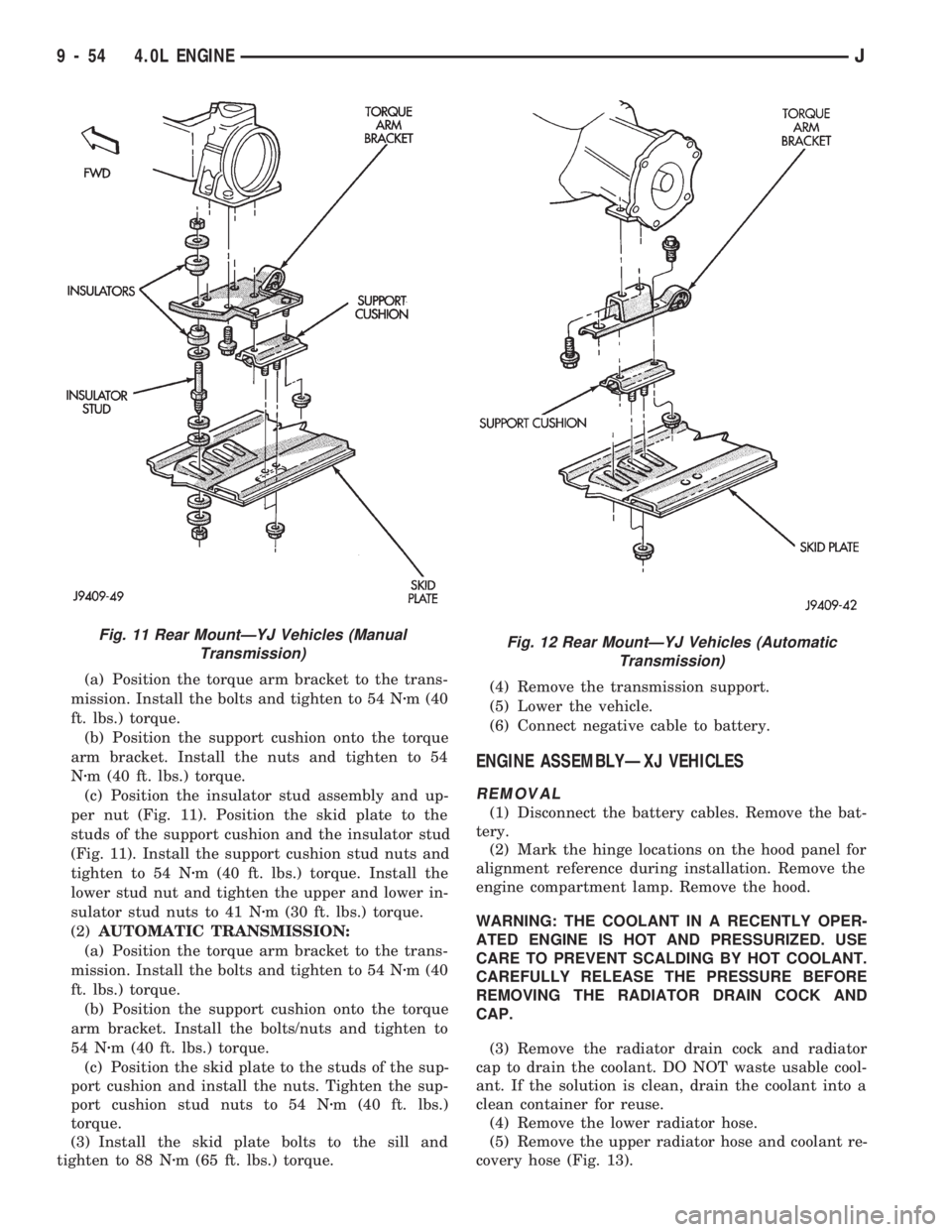
(a) Position the torque arm bracket to the trans-
mission. Install the bolts and tighten to 54 Nzm (40
ft. lbs.) torque.
(b) Position the support cushion onto the torque
arm bracket. Install the nuts and tighten to 54
Nzm (40 ft. lbs.) torque.
(c) Position the insulator stud assembly and up-
per nut (Fig. 11). Position the skid plate to the
studs of the support cushion and the insulator stud
(Fig. 11). Install the support cushion stud nuts and
tighten to 54 Nzm (40 ft. lbs.) torque. Install the
lower stud nut and tighten the upper and lower in-
sulator stud nuts to 41 Nzm (30 ft. lbs.) torque.
(2)AUTOMATIC TRANSMISSION:
(a) Position the torque arm bracket to the trans-
mission. Install the bolts and tighten to 54 Nzm (40
ft. lbs.) torque.
(b) Position the support cushion onto the torque
arm bracket. Install the bolts/nuts and tighten to
54 Nzm (40 ft. lbs.) torque.
(c) Position the skid plate to the studs of the sup-
port cushion and install the nuts. Tighten the sup-
port cushion stud nuts to 54 Nzm (40 ft. lbs.)
torque.
(3) Install the skid plate bolts to the sill and
tighten to 88 Nzm (65 ft. lbs.) torque.(4) Remove the transmission support.
(5) Lower the vehicle.
(6) Connect negative cable to battery.
ENGINE ASSEMBLYÐXJ VEHICLES
REMOVAL
(1) Disconnect the battery cables. Remove the bat-
tery.
(2) Mark the hinge locations on the hood panel for
alignment reference during installation. Remove the
engine compartment lamp. Remove the hood.
WARNING: THE COOLANT IN A RECENTLY OPER-
ATED ENGINE IS HOT AND PRESSURIZED. USE
CARE TO PREVENT SCALDING BY HOT COOLANT.
CAREFULLY RELEASE THE PRESSURE BEFORE
REMOVING THE RADIATOR DRAIN COCK AND
CAP.
(3) Remove the radiator drain cock and radiator
cap to drain the coolant. DO NOT waste usable cool-
ant. If the solution is clean, drain the coolant into a
clean container for reuse.
(4) Remove the lower radiator hose.
(5) Remove the upper radiator hose and coolant re-
covery hose (Fig. 13).
Fig. 11 Rear MountÐYJ Vehicles (Manual
Transmission)Fig. 12 Rear MountÐYJ Vehicles (Automatic
Transmission)
9 - 54 4.0L ENGINEJ