1994 JEEP CHEROKEE roof
[x] Cancel search: roofPage 1526 of 1784
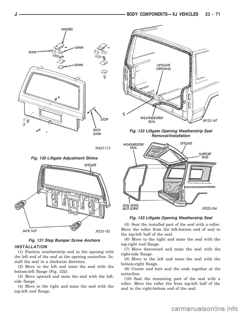
INSTALLATION
(1) Position weatherstrip seal in the opening with
the left end of the seal at the opening centerline. In-
stall the seal in a clockwise direction.
(2) Move to the left and mate the seal with the
bottom-left flange (Fig. 122).
(3) Move upward and mate the seal with the left-
side flange.
(4) Move to the right and mate the seal with the
top-left roof flange.(5) Seat the installed part of the seal with a roller.
Move the roller from the left-bottom end of seal to
the top-left half of the seal.
(6) Move to the right and mate the seal with the
top-right roof flange.
(7) Move downward and mate the seal with the
right-side flange.
(8) Move to the left and mate the seal with the
bottom-right flange.
(9) Center and butt seal the ends together at the
centerline.
(10) Seat the remaining part of the seal with a
roller. Move the roller the from top-left half of the
seal to the right-bottom end of the seal.
Fig. 130 Liftgate Adjustment Shims
Fig. 131 Stop Bumper Screw Anchors
Fig. 132 Liftgate Opening Weatherstrip Seal
Removal/Installation
Fig. 133 Liftgate Opening Weatherstrip Seal
JBODY COMPONENTSÐXJ VEHICLES 23 - 71
Page 1575 of 1784
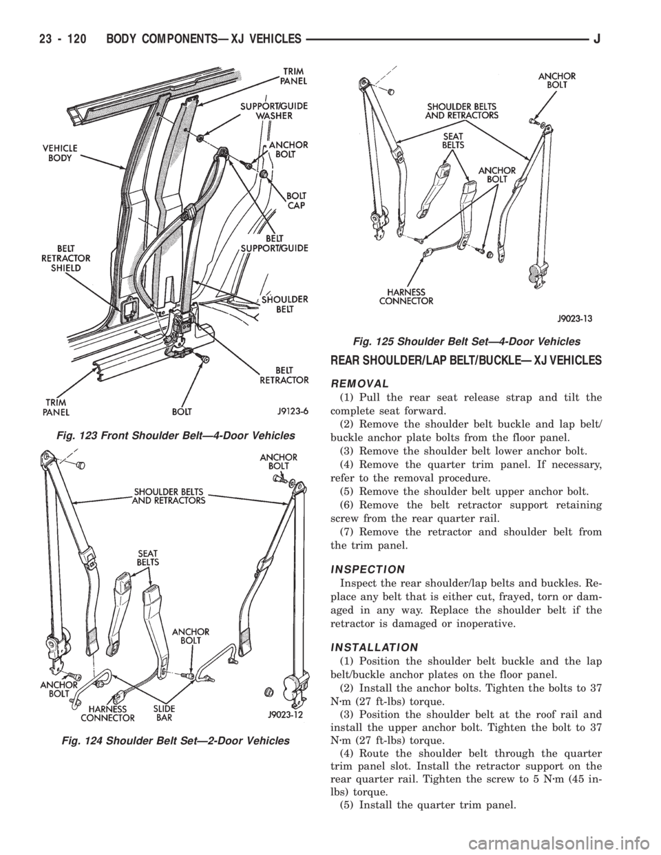
REAR SHOULDER/LAP BELT/BUCKLEÐXJ VEHICLES
REMOVAL
(1) Pull the rear seat release strap and tilt the
complete seat forward.
(2) Remove the shoulder belt buckle and lap belt/
buckle anchor plate bolts from the floor panel.
(3) Remove the shoulder belt lower anchor bolt.
(4) Remove the quarter trim panel. If necessary,
refer to the removal procedure.
(5) Remove the shoulder belt upper anchor bolt.
(6) Remove the belt retractor support retaining
screw from the rear quarter rail.
(7) Remove the retractor and shoulder belt from
the trim panel.
INSPECTION
Inspect the rear shoulder/lap belts and buckles. Re-
place any belt that is either cut, frayed, torn or dam-
aged in any way. Replace the shoulder belt if the
retractor is damaged or inoperative.
INSTALLATION
(1) Position the shoulder belt buckle and the lap
belt/buckle anchor plates on the floor panel.
(2) Install the anchor bolts. Tighten the bolts to 37
Nzm (27 ft-lbs) torque.
(3) Position the shoulder belt at the roof rail and
install the upper anchor bolt. Tighten the bolt to 37
Nzm (27 ft-lbs) torque.
(4) Route the shoulder belt through the quarter
trim panel slot. Install the retractor support on the
rear quarter rail. Tighten the screw to 5 Nzm (45 in-
lbs) torque.
(5) Install the quarter trim panel.
Fig. 123 Front Shoulder BeltÐ4-Door Vehicles
Fig. 124 Shoulder Belt SetÐ2-Door Vehicles
Fig. 125 Shoulder Belt SetÐ4-Door Vehicles
23 - 120 BODY COMPONENTSÐXJ VEHICLESJ
Page 1576 of 1784
(6) Install the shoulder belt lower anchor bolt.
Tighten the bolt to 37 Nzm (27 ft-lbs) torque.
(7) Return the rear seat to the normal position and
engage the latch.
HEADLINER
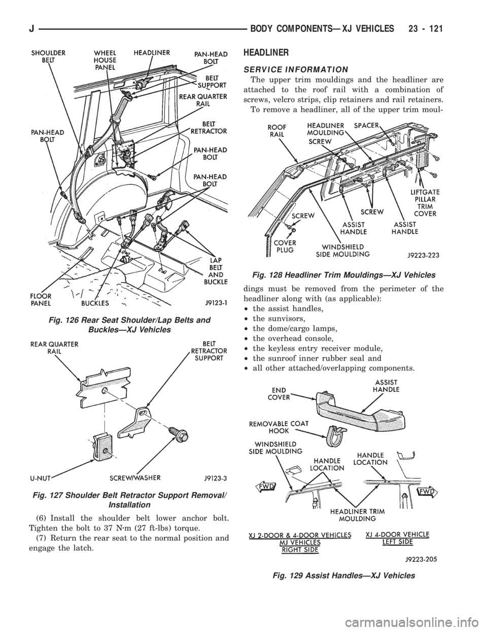
SERVICE INFORMATION
The upper trim mouldings and the headliner are
attached to the roof rail with a combination of
screws, velcro strips, clip retainers and rail retainers.
To remove a headliner, all of the upper trim moul-
dings must be removed from the perimeter of the
headliner along with (as applicable):
²the assist handles,
²the sunvisors,
²the dome/cargo lamps,
²the overhead console,
²the keyless entry receiver module,
²the sunroof inner rubber seal and
²all other attached/overlapping components.
Fig. 128 Headliner Trim MouldingsÐXJ Vehicles
Fig. 129 Assist HandlesÐXJ Vehicles
Fig. 126 Rear Seat Shoulder/Lap Belts and
BucklesÐXJ Vehicles
Fig. 127 Shoulder Belt Retractor Support Removal/
Installation
JBODY COMPONENTSÐXJ VEHICLES 23 - 121
Page 1577 of 1784
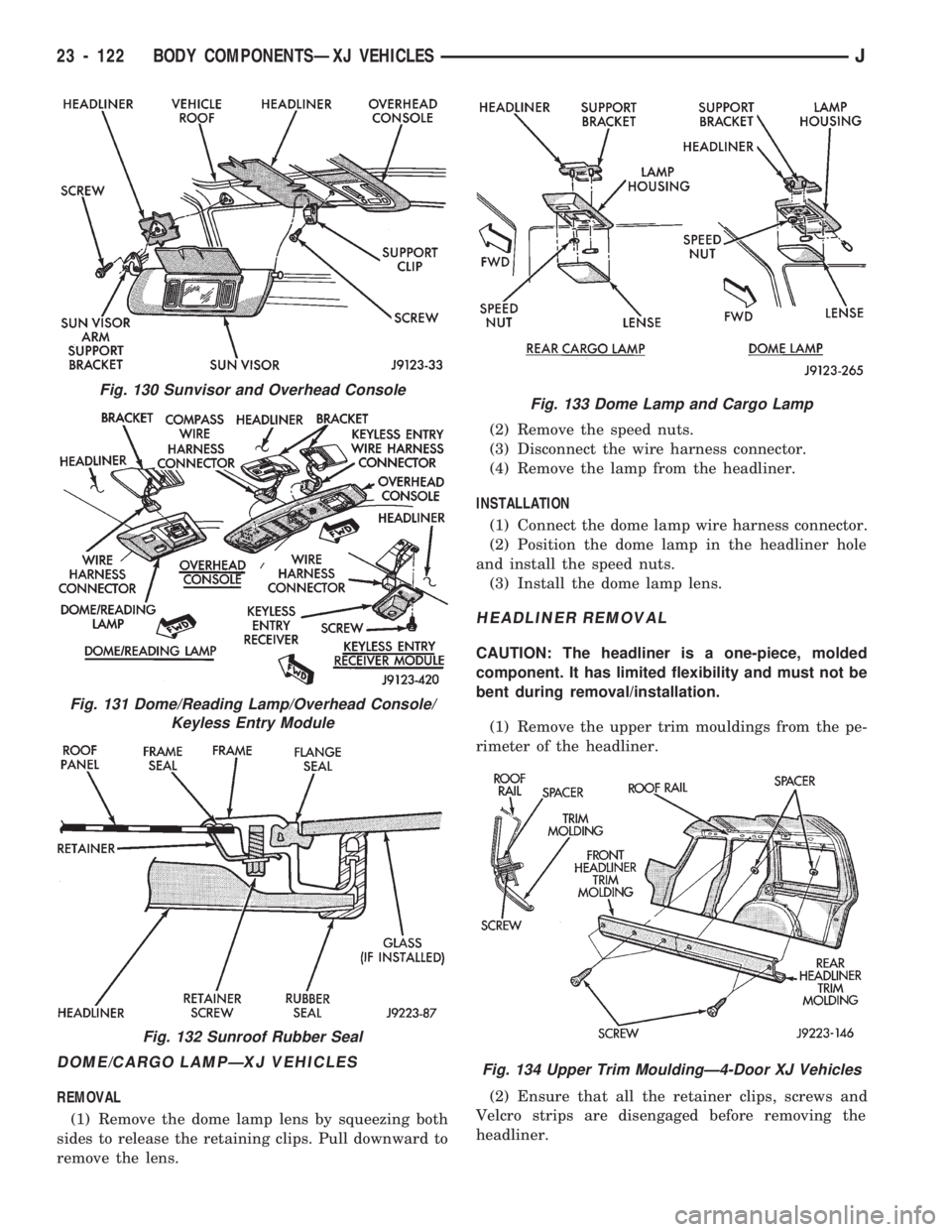
DOME/CARGO LAMPÐXJ VEHICLES
REMOVAL
(1) Remove the dome lamp lens by squeezing both
sides to release the retaining clips. Pull downward to
remove the lens.(2) Remove the speed nuts.
(3) Disconnect the wire harness connector.
(4) Remove the lamp from the headliner.
INSTALLATION
(1) Connect the dome lamp wire harness connector.
(2) Position the dome lamp in the headliner hole
and install the speed nuts.
(3) Install the dome lamp lens.
HEADLINER REMOVAL
CAUTION: The headliner is a one-piece, molded
component. It has limited flexibility and must not be
bent during removal/installation.
(1) Remove the upper trim mouldings from the pe-
rimeter of the headliner.
(2) Ensure that all the retainer clips, screws and
Velcro strips are disengaged before removing the
headliner.
Fig. 130 Sunvisor and Overhead Console
Fig. 131 Dome/Reading Lamp/Overhead Console/
Keyless Entry Module
Fig. 132 Sunroof Rubber Seal
Fig. 133 Dome Lamp and Cargo Lamp
Fig. 134 Upper Trim MouldingÐ4-Door XJ Vehicles
23 - 122 BODY COMPONENTSÐXJ VEHICLESJ
Page 1578 of 1784
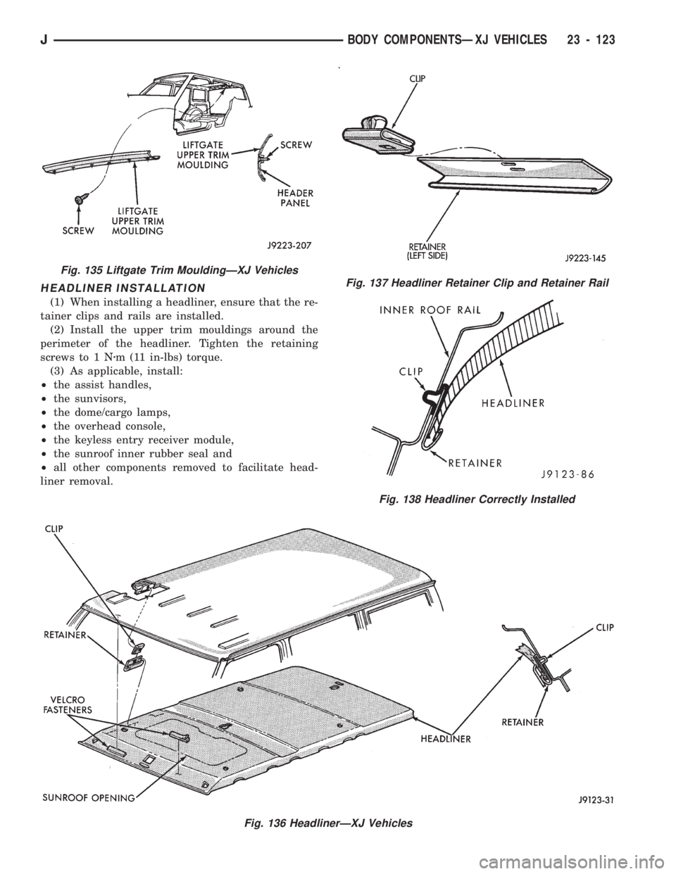
HEADLINER INSTALLATION
(1) When installing a headliner, ensure that the re-
tainer clips and rails are installed.
(2) Install the upper trim mouldings around the
perimeter of the headliner. Tighten the retaining
screws to 1 Nzm (11 in-lbs) torque.
(3) As applicable, install:
²the assist handles,
²the sunvisors,
²the dome/cargo lamps,
²the overhead console,
²the keyless entry receiver module,
²the sunroof inner rubber seal and
²all other components removed to facilitate head-
liner removal.
Fig. 136 HeadlinerÐXJ Vehicles
Fig. 137 Headliner Retainer Clip and Retainer Rail
Fig. 138 Headliner Correctly Installed
Fig. 135 Liftgate Trim MouldingÐXJ Vehicles
JBODY COMPONENTSÐXJ VEHICLES 23 - 123
Page 1579 of 1784
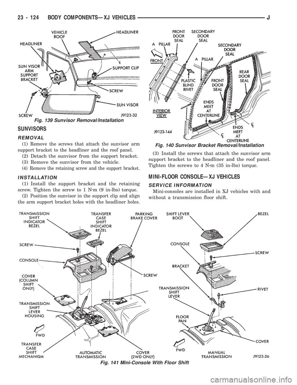
SUNVISORS
REMOVAL
(1) Remove the screws that attach the sunvisor arm
support bracket to the headliner and the roof panel.
(2) Detach the sunvisor from the support bracket.
(3) Remove the sunvisor from the vehicle.
(4) Remove the retaining screw and the support bracket.
INSTALLATION
(1) Install the support bracket and the retaining
screw. Tighten the screw to 1 Nzm (9 in-lbs) torque.
(2) Position the sunvisor in the support clip and align
the arm support bracket holes with the headliner holes.
(3) Install the screws that attach the sunvisor arm
support bracket to the headliner and the roof panel.
Tighten the screws to 4 Nzm (35 in-lbs) torque.
MINI-FLOOR CONSOLEÐXJ VEHICLES
SERVICE INFORMATION
Mini-consoles are installed in XJ vehicles with and
without a transmission floor shift.
Fig. 139 Sunvisor Removal/Installation
Fig. 140 Sunvisor Bracket Removal/Installation
Fig. 141 Mini-Console With Floor Shift
23 - 124 BODY COMPONENTSÐXJ VEHICLESJ
Page 1589 of 1784
EXTERIOR COMPONENTS
INDEX
page page
Battery Tray........................... 140
Body Extension Panels and FasciasÐYJ
Renegade Vehicles..................... 147
Body Side Step Moulding................. 145
Body Stripes/Decals..................... 153
Cowl Grille and Screen................... 139
Cowl Weatherstrip Seal................... 139
Exterior Nameplates (Adhesive-Backed)....... 158
External Spare/Wheel Tire Carrier........... 172
Fender Flare........................... 144
Fender Inner Splash Shields............... 147
Fender Splash Aprons.................... 147
Fenders............................... 141
Fog LampÐYJ Renegade Vehicles.......... 150
Front Fascia and Skid PlateÐYJ Renegade
Vehicles............................. 148
Front Fender Extension PanelÐYJ Renegade
Vehicles............................. 149
Fuel Filler Protector/Nozzle................ 158
Half Metal Door Mirror (External)............ 158
Hard Top Liftgate Glass.................. 162
Hard Top Repair........................ 165
Hard Top Roof Vent..................... 165
Hard Top Service....................... 164
Hard Top Service Information.............. 164Hood................................. 137
Hood Alignment......................... 138
Hood Insulator Panel..................... 138
Hood Safety Latch....................... 139
Liftgate Glass Weatherstrip Seal Replacement . . 163
Radiator Grille Applique................... 134
Rear Fascia and Skid PlateÐYJ Renegade
Vehicles............................. 152
Rear Quarter Extension PanelÐYJ Renegade
Vehicles............................. 151
Rocker Extension PanelÐYJ Renegade
Vehicles............................. 150
Soft Top Service........................ 167
Soft Top Service Information............... 166
Sport Bar............................. 171
Tailgate Adjustment...................... 160
Tailgate Hinge.......................... 159
Tailgate Latch and Release Handle.......... 160
Tailgate Latch Striker..................... 161
Tailgate Lock Cylinder.................... 160
Tailgate Service......................... 159
Tailgate Service Information................ 159
Tailgate Weatherstrip Seal................. 161
Wheelhouse Splash Liners................ 146
RADIATOR GRILLE APPLIQUE
REMOVAL
(1) Raise the hood.
(2) Remove the headlamp bezels (Fig. 1).
(3) Remove the headlamp bulb retainer screws
(Fig. 2).
(4) Disconnect and remove the headlamps and
buckets as a unit (Fig. 2).
(5) Remove the parking lamp retaining screws
(Fig. 2).
(6) Disconnect the wire harness connectors and re-
move the parking lamps (Fig. 2).
(7) Remove the front crossmember cover.
(8) Remove the retaining screws and the bumper
inserts at the top of the grille panel (Fig. 1).
(9) Detach the grille applique from the grille panel
(Fig. 1).
(10) Remove the double faced foam adhesive tape
at the bottom of the grille applique (Fig. 1).
INSTALLATION
(1) Install double faced foam tape at the bottom,
interior side of the grille applique (Fig. 1).
(2) Position the grille applique over the grille
panel and press inward along the bottom where the
tape is located (Fig. 1).
(3) Install the grille applique retaining screws and
the bumper inserts (Fig. 1).(4) Connect the wire harness connectors and posi-
tion the headlamp buckets and headlamps in the
grille panel (Fig. 2).
(5) Install the headlamp bulb retainer and the
screws (Fig. 1). Tighten the screws to 2 Nzm (18 in-
lbs) torque.
(6) Install the headlamp bezels and the retaining
screws (Fig. 1). Tighten the screws securely.
(7) Connect the wire harness connectors and in-
stall the parking lamps (Fig. 2).
(8) Install the parking lamp retaining screws.
Tighten the screws to 2 Nzm (18 in-lbs) torque.
(9) Close the hood.
(10) Install the front crossmember cover.
23 - 134 BODY COMPONENTSÐXJ VEHICLESJ
Page 1620 of 1784
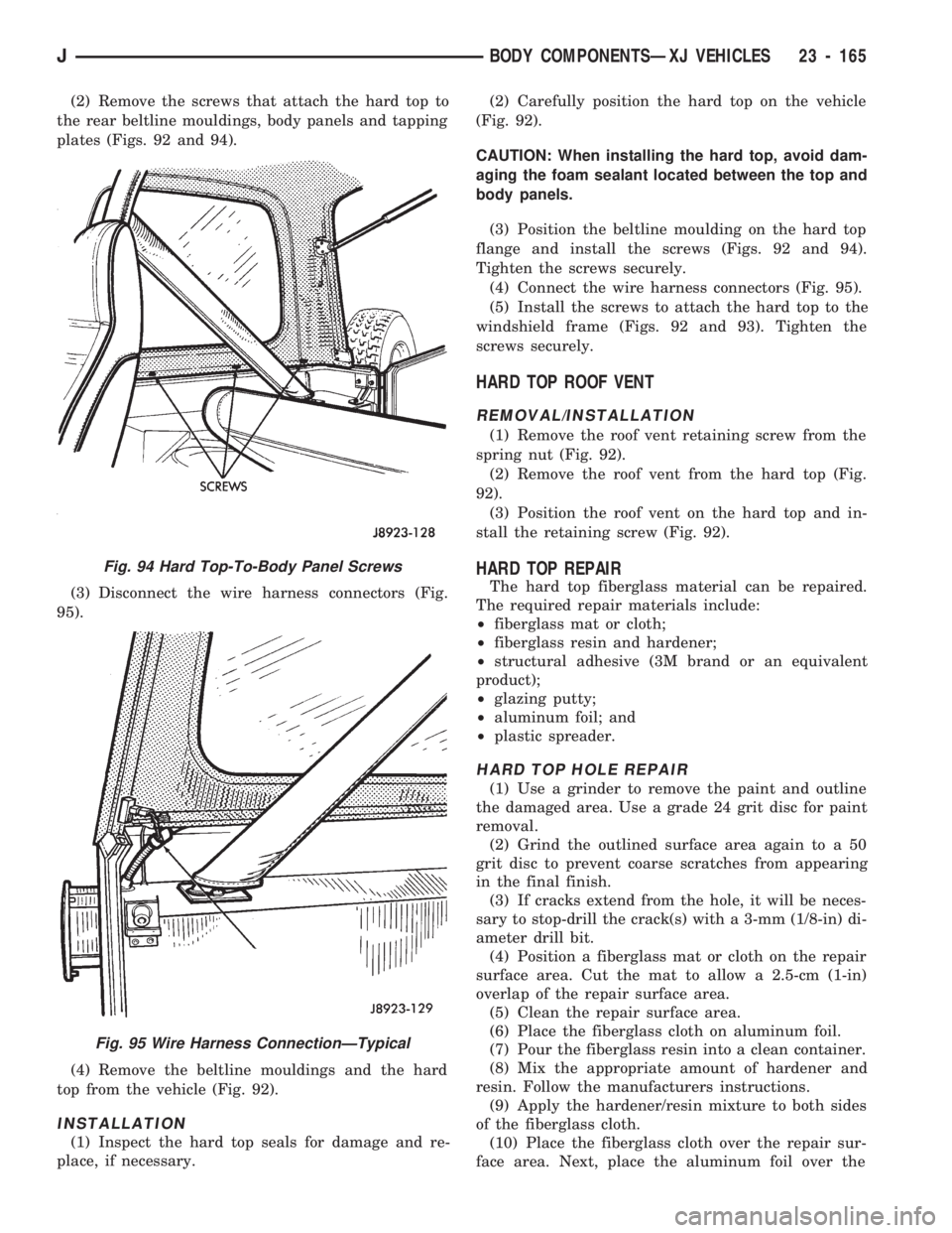
(2) Remove the screws that attach the hard top to
the rear beltline mouldings, body panels and tapping
plates (Figs. 92 and 94).
(3) Disconnect the wire harness connectors (Fig.
95).
(4) Remove the beltline mouldings and the hard
top from the vehicle (Fig. 92).
INSTALLATION
(1) Inspect the hard top seals for damage and re-
place, if necessary.(2) Carefully position the hard top on the vehicle
(Fig. 92).
CAUTION: When installing the hard top, avoid dam-
aging the foam sealant located between the top and
body panels.
(3) Position the beltline moulding on the hard top
flange and install the screws (Figs. 92 and 94).
Tighten the screws securely.
(4) Connect the wire harness connectors (Fig. 95).
(5) Install the screws to attach the hard top to the
windshield frame (Figs. 92 and 93). Tighten the
screws securely.
HARD TOP ROOF VENT
REMOVAL/INSTALLATION
(1) Remove the roof vent retaining screw from the
spring nut (Fig. 92).
(2) Remove the roof vent from the hard top (Fig.
92).
(3) Position the roof vent on the hard top and in-
stall the retaining screw (Fig. 92).
HARD TOP REPAIR
The hard top fiberglass material can be repaired.
The required repair materials include:
²fiberglass mat or cloth;
²fiberglass resin and hardener;
²structural adhesive (3M brand or an equivalent
product);
²glazing putty;
²aluminum foil; and
²plastic spreader.
HARD TOP HOLE REPAIR
(1) Use a grinder to remove the paint and outline
the damaged area. Use a grade 24 grit disc for paint
removal.
(2) Grind the outlined surface area again to a 50
grit disc to prevent coarse scratches from appearing
in the final finish.
(3) If cracks extend from the hole, it will be neces-
sary to stop-drill the crack(s) with a 3-mm (1/8-in) di-
ameter drill bit.
(4) Position a fiberglass mat or cloth on the repair
surface area. Cut the mat to allow a 2.5-cm (1-in)
overlap of the repair surface area.
(5) Clean the repair surface area.
(6) Place the fiberglass cloth on aluminum foil.
(7) Pour the fiberglass resin into a clean container.
(8) Mix the appropriate amount of hardener and
resin. Follow the manufacturers instructions.
(9) Apply the hardener/resin mixture to both sides
of the fiberglass cloth.
(10) Place the fiberglass cloth over the repair sur-
face area. Next, place the aluminum foil over the
Fig. 94 Hard Top-To-Body Panel Screws
Fig. 95 Wire Harness ConnectionÐTypical
JBODY COMPONENTSÐXJ VEHICLES 23 - 165