1994 JEEP CHEROKEE fuse
[x] Cancel search: fusePage 410 of 1784
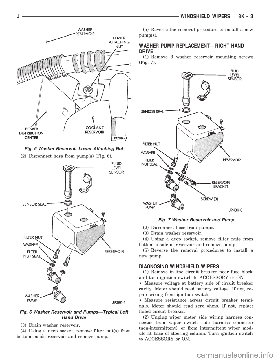
(2) Disconnect hose from pump(s) (Fig. 6).
(3) Drain washer reservoir.
(4) Using a deep socket, remove filter nut(s) from
bottom inside reservoir and remove pump.(5) Reverse the removal procedure to install a new
pump(s).
WASHER PUMP REPLACEMENTÐRIGHT HAND
DRIVE
(1) Remove 3 washer reservoir mounting screws
(Fig. 7).
(2) Disconnect hose from pumps.
(3) Drain washer reservoir.
(4) Using a deep socket, remove filter nuts from
bottom inside of reservoir and remove pump.
(5) Reverse the removal procedures to install a
new pump.
DIAGNOSING WINDSHIELD WIPERS
(1) Remove in-line circuit breaker near fuse block
and turn ignition switch to ACCESSORY or ON.
²Measure voltage at battery side of circuit breaker
cavity. Meter should read battery voltage. If not, re-
pair wiring from ignition switch.
²Measure resistance across circuit breaker termi-
nals. Meter should read zero ohms. If not, replace
failed circuit breaker.
(2) Unplug wiper motor side wiring harness con-
nector from wiper switch side harness connector
(non-intermittent), or from intermittent wiper mod-
ule at base of steering column. Turn ignition switch
to ACCESSORY or ON.
Fig. 5 Washer Reservoir Lower Attaching Nut
Fig. 6 Washer Reservoir and PumpsÐTypical Left
Hand Drive
Fig. 7 Washer Reservoir and Pump
JWINDSHIELD WIPERS 8K - 3
Page 413 of 1784
(2) Install the mounting screws.
(3) Connect the wiring harness.
(4) Install the pivot pin, seal, bezel and attaching
nut (Fig. 2). Torque nut to 4 Nzm (32 in. lbs.).
(5) Connect interior washer hose.
Lubricate the bezel nipples with a small amount
of water and then install the washer hoses.
(6) Install the liftgate trim panel.
(7) Install the wiper arm assembly and connect the
external washer hose to the bezel.
(8) Slide the clip along the hose until it is over
hose mount.
The blade should be parallel to window open-
ing and no closer than 5mm to window seal
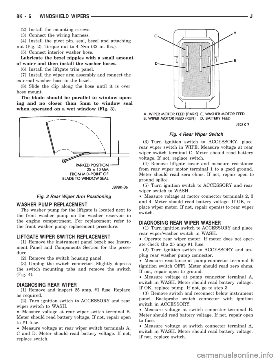
when operated on a wet window (Fig. 3).
WASHER PUMP REPLACEMENT
The washer pump for the liftgate is located next to
the front washer pump on the washer reservoir in
the engine compartment. For replacement refer to
the front washer pump replacement procedure.
LIFTGATE WIPER SWITCH REPLACEMENT
(1) Remove the instrument panel bezel; see Instru-
ment Panel and Components Section for the proce-
dure.
(2) Remove the switch housing panel.
(3) Unplug the switch connector. Slightly depress
the switch mounting tabs and remove the switch
(Fig. 4).
DIAGNOSING REAR WIPER
(1) Remove and inspect 25 amp, #1 fuse. Replace
as required.
(2) Turn ignition switch to ACCESSORY and rear
wiper switch to WASH.
²Measure voltage at rear wiper switch terminal B.
Meter should read battery voltage. If not, repair open
to #1 fuse.
²Measure voltage at rear wiper switch terminals A,
C and D. Meter should read battery voltage. If not,
replace switch.(3) Turn ignition switch to ACCESSORY, place
rear wiper switch in WIPE. Measure voltage at rear
wiper switch terminal C. Meter should read battery
voltage. If not, replace switch.
(4) Remove liftgate cover and measure resistance
from rear wiper motor terminal 1 to a good ground.
Meter should read zero ohms. If not, repair open to
ground splice.
(5) Turn ignition switch to ACCESSORY and rear
wiper switch to WASH.
²Measure voltage at motor connector terminals 2, 3
and 4. Meter should read battery voltage. If OK, re-
place wiper motor. If not, repair open(s) to rear wiper
switch.
DIAGNOSING REAR WIPER WASHER
(1) Turn ignition switch to ACCESSORY and place
rear wiper/washer switch in WASH.
²Operate rear wiper motor. If motor does not oper-
ate check the 25 amp #1 fuse.
(2) Turn ignition switch to ACCESSORY and un-
plug rear washer pump connector.
²Measure resistance at pump connector terminal B
(ignition switch OFF). Meter should read zero ohms.
If not, repair open to ground.
²Measure voltage at pump connector terminal A,
switch in WASH. Meter should read battery voltage.
If OK, replace pump. If not, go to step 3.
(3) Remove switch and reconnect below instrument
panel. Backprobe switch connector with ignition
switch in ACCESSORY.
²Measure voltage at switch connector terminal B.
Meter should read battery voltage. If not, repair open
to fuse.
²Measure voltage at switch connector terminal A,
switch in WASH. Meter should read battery voltage.
If not, replace switch.
Fig. 3 Rear Wiper Arm Positioning
Fig. 4 Rear Wiper Switch
8K - 6 WINDSHIELD WIPERSJ
Page 418 of 1784
(2) Remove the windshield holddown bolts in the
lower corners of the instrument panel.
(3) Remove wiper motor mounting screws (Fig. 4).
(4) Remove wiper motor harness retaining clip lo-
cated on bottom of windshield.
(5) Disconnect the wiper linkage drive arm (Fig. 5)
(6) Grasp the motor and pull the motor and drive
arm out of the access hole (Fig. 6).
(7) Pry the drive arm off the motor pivot. DO NOT
remove the pivot attaching nut (Fig. 7).
(8) Remove 2 screws holding intermittent wipe
module bracket to bottom of instrument panel.
(9) Reach up behind instrument panel and discon-
nect wiper motor harness.
(10) Remove wiper motor.
INSTALLATION
(1) Install wire harness through hole in top of in-
strument panel.
(2) Connect wiper motor connector behind instru-
ment panel.
(3) Install intermittent wipe module bracket to
bottom of instrument panel.
(4) Turn wipers on to allow motor to cycle to park
position.
(5) Install wiper linkage drive arm onto motor
(Fig. 8).
(6) Install motor and drive arm in the windshield
frame.
(7) Connect wiper linkage drive arm to pivot shaft
(Fig. 9).
(8) Install motor mounting screws. Tighten screws
to 10.5 Nzm (96 in. lbs.).
(9) Install wire harness retaining clip on bottom of
windshield.
Be sure wire harness is not pinched or cut when
windshield frame is rotated to upright position.
(10) Raise windshield to upright position and in-
stall left and right windshield holddown bolts.
(11) Install the necessary top components on wind-
shield frame.
WASHER PUMP REPLACEMENT
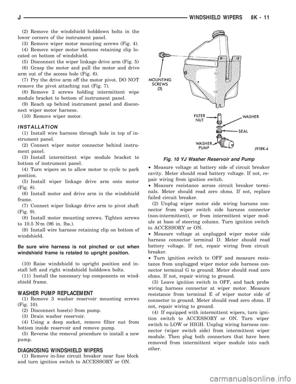
(1) Remove 3 washer reservoir mounting screws
(Fig. 10).
(2) Disconnect hose(s) from pump.
(3) Drain washer reservoir.
(4) Using a deep socket, remove filter nut from
bottom inside reservoir and remove pump.
(5) Reverse the removal procedure to install a new
pump.
DIAGNOSING WINDSHIELD WIPERS
(1) Remove in-line circuit breaker near fuse block
and turn ignition switch to ACCESSORY or ON.²Measure voltage at battery side of circuit breaker
cavity. Meter should read battery voltage. If not, re-
pair wiring from ignition switch.
²Measure resistance across circuit breaker termi-
nals. Meter should read zero ohms. If not, replace
failed circuit breaker.
(2) Unplug wiper motor side wiring harness con-
nector from wiper switch side harness connector
(non-intermittent), or from intermittent wiper mod-
ule at base of steering column. Turn ignition switch
to ACCESSORY or ON.
²Measure voltage at unplugged wiper motor side
harness connector terminal D. Meter should read
battery voltage. If not, repair wiring from circuit
breaker.
²Turn ignition switch to OFF and measure resis-
tance from unplugged wiper motor side harness con-
nector terminal G to ground. Meter should read zero
ohms. If not, repair wiring to ground.
(3) Leave ignition switch in OFF, and back probe
wiring harness connector at wiper motor. Measure
resistance from terminal E of wiper motor side of
connector to ground. Meter should read zero ohms. If
not, repair wiring to ground.
(4) If equipped with intermittent wipers, turn igni-
tion switch to ACCESSORY or ON. Turn wiper
switch to LOW or HIGH. Unplug wiring harness con-
nector (wiper switch side) from intermittent wiper
module. Then plug both connectors that have been
removed from intermittent wiper module into each
other.
Fig. 10 YJ Washer Reservoir and Pump
JWINDSHIELD WIPERS 8K - 11
Page 421 of 1784
DIAGNOSING REAR WIPER/WASHER
Refer to Group 8W - Wiring Diagrams.
(1) Turn ignition switch to ON and rear wiper/
washer switch to WASH.
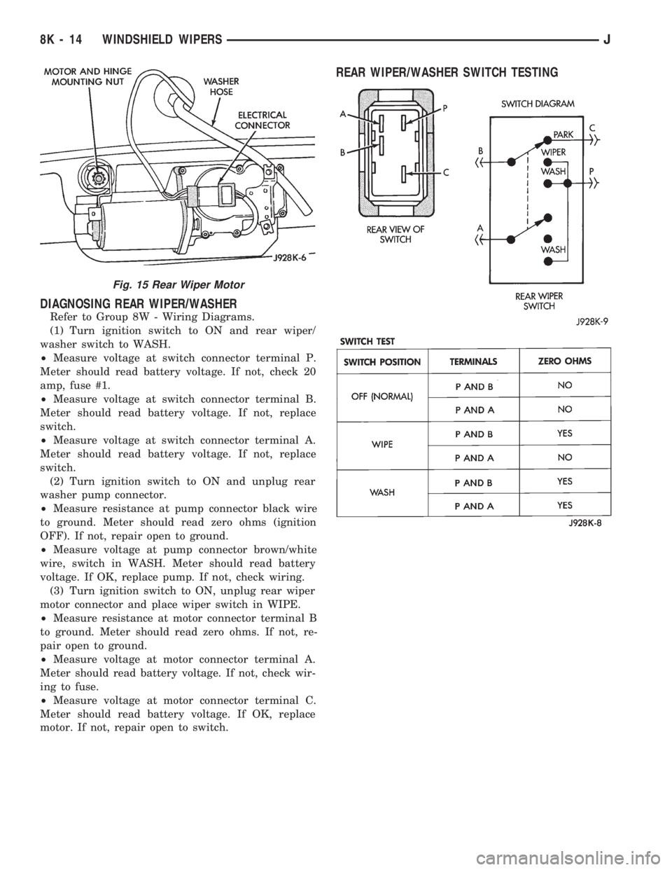
²Measure voltage at switch connector terminal P.
Meter should read battery voltage. If not, check 20
amp, fuse #1.
²Measure voltage at switch connector terminal B.
Meter should read battery voltage. If not, replace
switch.
²Measure voltage at switch connector terminal A.
Meter should read battery voltage. If not, replace
switch.
(2) Turn ignition switch to ON and unplug rear
washer pump connector.
²Measure resistance at pump connector black wire
to ground. Meter should read zero ohms (ignition
OFF). If not, repair open to ground.
²Measure voltage at pump connector brown/white
wire, switch in WASH. Meter should read battery
voltage. If OK, replace pump. If not, check wiring.
(3) Turn ignition switch to ON, unplug rear wiper
motor connector and place wiper switch in WIPE.
²Measure resistance at motor connector terminal B
to ground. Meter should read zero ohms. If not, re-
pair open to ground.
²Measure voltage at motor connector terminal A.
Meter should read battery voltage. If not, check wir-
ing to fuse.
²Measure voltage at motor connector terminal C.
Meter should read battery voltage. If OK, replace
motor. If not, repair open to switch.
REAR WIPER/WASHER SWITCH TESTING
Fig. 15 Rear Wiper Motor
8K - 14 WINDSHIELD WIPERSJ
Page 428 of 1784
LAMPS
CONTENTS
page page
EXTERIOR LAMPS....................... 1
INTERIOR LAMPS...................... 19SPECIFICATIONS....................... 23
EXTERIOR LAMPS
INDEX
page page
Back-up/Rear Turn Signal/Tail Lamp Bulb
Replacement........................... 9
Center High Mounted Stop Lamp (CHMSL)ÐXJ . 10
Center High Mounted Stop Lamp (CHMSL)ÐYJ . 11
Daytime Running Lights (Canada Only)........ 16
DRL Module Replacement.................. 16
Fog Lamp Beam Adjustment................ 12
Fog Lamp Bulb/Element Replacement......... 13
Fog Lamp Replacement................... 15
Fog Lamp Service Information............... 12
Fog Lamp Switch Replacement.............. 14
Fog Lamp Trouble Diagnosis................ 12
Front Park/Turn Signal Lamp Bulb Replacement . . 8
Headlamp Beam Adjustment................. 3
Headlamp Bulb Replacement................ 3
Headlamp Delay Function Trouble DiagnosisÐXJ
Vehicles.............................. 16Headlamp Delay Module ReplacementÐXJ
Vehicles.............................. 16
Headlamp Dimmer Switch Replacement........ 6
Headlamp Switch Replacement............... 4
Headlamp Trouble DiagnosisÐXJ Vehicles...... 1
Headlamp Trouble DiagnosisÐYJ Vehicles...... 2
License Plate Lamp....................... 10
Sentinel Headlamp Delay ModuleÐXJ Vehicles . . 15
Service Information........................ 1
Side Marker Lamp Bulb Replacement.......... 7
Switch Tests............................. 2
Underhood Lamp Bulb Replacement.......... 18
Underhood Lamp Replacement.............. 18
Underhood Lamp Service Information......... 17
SERVICE INFORMATION
Exterior lamp circuits are comprised of the head-
lamp circuit, fog lamp circuit, and tail/side marker/
park lamp circuit. Battery voltage is controlled by
both the headlamp ON/OFF switch and headlamp
dimmer switch.
The dimmer switch functions as a fog lamp switch.
Voltage is applied to the fog lamp switch only when
the dimmer switch is in the low beam position.
HEADLAMP TROUBLE DIAGNOSISÐXJ VEHICLES
LOW AND HIGH BEAM INOPERATIVE BOTH
HEADLAMPS
(1) Place the headlamp switch in the ON position.
(2) Test the 40 amp fuse for continuity. If bad, re-
place fuse.
(3) Insert the test probe into terminal 5 of the
front lamp wire harness connector. Measure the re-
sistance from terminal 5 to body ground. The ohm-
meter should indicate zero ohms. If not OK, repair
the open circuit in the harness to body ground.(4) Disconnect the front lamp wire connector. Mea-
sure resistance between connector terminals 5 and 2.
Next measure between terminal 5 and 7. The ohm-
meter should indicate zero ohms for both measure-
ments. If not OK, replace the headlamp bulbs.
(5) Measure the voltage between the dimmer
switch wire connector terminal 2 and body ground.
The voltmeter should indicate battery voltage. If not
OK, continue with the next step.
The dimmer switch is integral with the turn
signal and is located on the steering column.
The dimmer switch switches the headlamp beam
when the turn signal lever is pulled rearward.
(6) Disconnect the dimmer switch wire connector
and place the headlamp switch in the OFF position.
Measure the resistance from terminal 2 to vehicle
body ground. The ohmmeter should indicate infinite
resistance. If OK, replace the headlamp switch and
continue with the next step. If not OK, repair the
short circuit in the wire harness that leads to termi-
nal 2.
JLAMPS 8L - 1
Page 429 of 1784
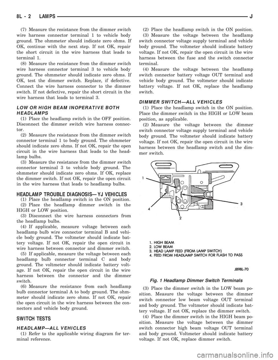
(7) Measure the resistance from the dimmer switch
wire harness connector terminal 1 to vehicle body
ground. The ohmmeter should indicate zero ohms. If
OK, continue with the next step. If not OK, repair
the short circuit in the wire harness that leads to
terminal 1.
(8) Measure the resistance from the dimmer switch
wire harness connector terminal 3 to vehicle body
ground. The ohmmeter should indicate zero ohms. If
OK, test the dimmer switch. Replace, if defective.
Connect the wire harness connector to the dimmer
switch. If not defective, repair the short circuit in the
wire harness that leads to terminal 3.
LOW OR HIGH BEAM INOPERATIVE BOTH
HEADLAMPS
(1) Place the headlamp switch in the OFF position.
Disconnect the dimmer switch wire harness connec-
tor.
(2) Measure the resistance from the dimmer switch
connector terminal 1 to body ground. The ohmmeter
should indicate zero ohms. If not OK, repair the open
circuit in the wire harness that leads to the head-
lamp bulbs.
(3) Measure the resistance from the dimmer switch
connector terminal 3 to vehicle body ground. The
ohmmeter should indicate zero ohms. If OK, replace
the dimmer switch. If not OK, repair the open circuit
in the wire harness that leads to headlamp bulbs.
HEADLAMP TROUBLE DIAGNOSISÐYJ VEHICLES
(1) Place the headlamp switch in the ON position.
(2) Place the headlamp dimmer switch in the
HIGH or LOW position.
(3) Disconnect the wire harness connectors from
the headlamp bulbs.
(4) If applicable, measure voltage between each
headlamp bulb wire connector terminal B and vehi-
cle body ground. The voltmeter should indicate bat-
tery voltage. If not OK, repair the open circuit in
wire harness between connector and dimmer switch.
(5) If applicable, measure the voltage between each
headlamp bulb connector terminal C and body
ground. The voltmeter should indicate battery volt-
age. If not OK, repair the open circuit in the wire
harness between the connector and the dimmer
switch.
(6) Measure the resistance from each headlamp
bulb connector terminal A to body ground. The ohm-
meter should indicate zero ohms. If not OK, repair
the open circuit in the wire harness between the con-
nectors and vehicle body ground.
SWITCH TESTS
HEADLAMPÐALL VEHICLES
(1) Refer to the applicable wiring diagram for ter-
minal reference.(2) Place the headlamp switch in the ON position.
(3) Measure the voltage between the headlamp
switch connector voltage supply terminal and vehicle
body ground. The voltmeter should indicate battery
voltage. If not OK, repair the open circuit in the wire
harness between the fuse and the switch connector
terminal.
(4) Measure the voltage between the headlamp
switch connector battery voltage OUT terminal and
vehicle body ground. The voltmeter should indicate
battery voltage. If not OK, replace the headlamp
switch.
DIMMER SWITCHÐALL VEHICLES
(1) Place the headlamp switch in the ON position.
Place the dimmer switch in the HIGH or LOW beam
position, as applicable.
(2) Measure the voltage between the dimmer
switch connector voltage supply terminal and vehicle
body ground. The voltmeter should indicate battery
voltage. If not OK, repair the open circuit in the wire
harness between the headlamp switch and the dim-
mer switch.
(3) Place the dimmer switch in the LOW beam po-
sition. Measure the voltage between the dimmer
switch connector low beam voltage OUT terminal
and body ground. The voltmeter should indicate bat-
tery voltage. If not OK, replace the dimmer switch.
(4) Place the dimmer switch in the HIGH beam po-
sition. Measure the voltage between the dimmer
switch connector high beam voltage OUT terminal
and body ground. Voltmeter should indicate battery
voltage. If not OK, replace dimmer switch.
Fig. 1 Headlamp Dimmer Switch Terminals
8L - 2 LAMPSJ
Page 443 of 1784
switch is turned OFF. The driver engages the module
by turning the ignition switch OFF, then turning the
headlamps OFF.
The headlamp delay module is located behind the
I/P next to the headlamp switch.
HEADLAMP DELAY MODULE REPLACEMENTÐXJ
VEHICLES
The headlamp delay module is attached to the in-
side of the instrument panel to the right of the head-
lamp switch.
REMOVAL
(1) Remove the lower instrument panel.
(2) Remove the screw that attaches the module to
the inside of the instrument panel.
(3) Disconnect the wire harness connector and re-
move the module from the instrument panel.
INSTALLATION
(1) Position the module inside the I/P and connect
the wire harness connector to the module.
(2) Install the screw that attaches the module to
the inside of the instrument panel.(3) Remove the lower instrument panel.
HEADLAMP DELAY FUNCTION TROUBLE
DIAGNOSISÐXJ VEHICLES
DELAY FUNCTION INOPERATIVE
(1) Remove, inspect and test the HD LP DLY fuse.
Replace if defective.
(2) Remove the delay module from the I/P. Do not
disconnect the wire harness connector. Turn the igni-
tion switch to the RUN position. Place the headlamp
switch in headlamps ON position. Turn the ignition
to the OFF position for a resistance test.
(3) Measure the resistance from the delay module
terminal 4 to vehicle body ground. The ohmmeter
should indicate zero ohms. If not, repair the open cir-
cuit in the wire harness to vehicle body ground.
(4) Measure the voltage between the delay module
terminal 8 and vehicle body ground. The voltmeter
should indicate battery voltage. If not, repair the
open circuit in the wire harness to the instrument
cluster indicator connector terminal 14.
(5) Measure the voltage between the delay module
terminal 6 and vehicle body ground. The voltmeter
should indicate battery voltage. If not, repair the
open circuit in the wire harness to the headlamp
switch.
(6) Measure the voltage between the delay module
terminal 2 and vehicle body ground. The voltmeter
should indicate battery voltage. If not, repair the
open circuit in the wire harness to the fuse.
DAYTIME RUNNING LIGHTS (CANADA ONLY)
SERVICE INFORMATION
The Daytime Running Lights (Headlamps) System
is installed on vehicles manufactured for sale in Can-
ada only. The headlamps are illuminated when the
ignition switch is turned to the ON position. The
DRL module receives a vehicle-moving signal from
the vehicle speed sensor. This provides a constant
headlamps-oncondition as long as the vehicle is
moving. The lamps are illuminated at less than 50
percent of normal intensity.
DRL MODULE REPLACEMENT
REMOVALÐXJ VEHICLES
The Daytime Running Lights (DRL) module is lo-
cated on the right fender inner panel adjacent to the
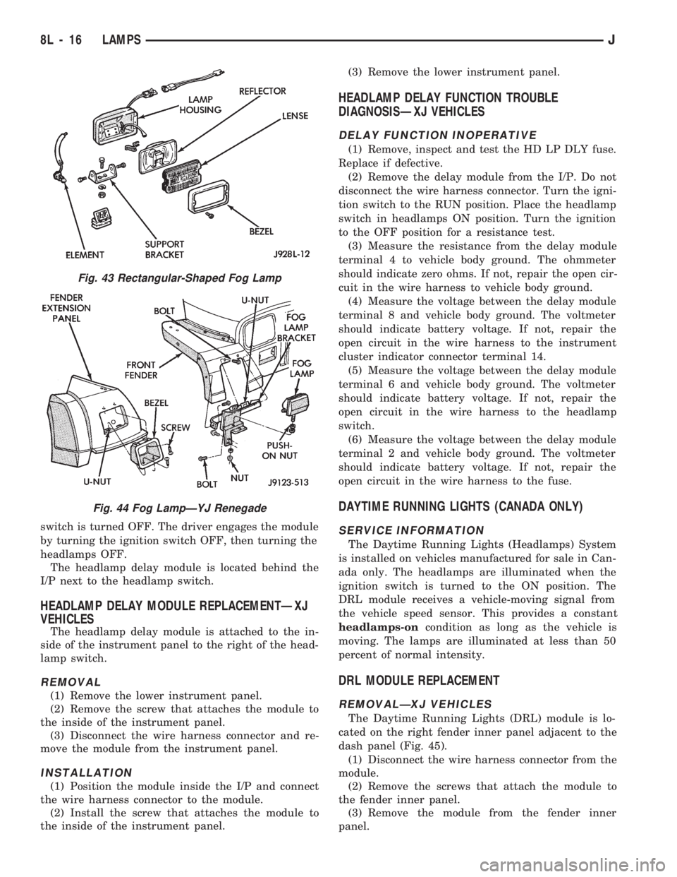
dash panel (Fig. 45).
(1) Disconnect the wire harness connector from the
module.
(2) Remove the screws that attach the module to
the fender inner panel.
(3) Remove the module from the fender inner
panel.
Fig. 43 Rectangular-Shaped Fog Lamp
Fig. 44 Fog LampÐYJ Renegade
8L - 16 LAMPSJ
Page 446 of 1784
INTERIOR LAMPS
INDEX
page page
Dome Lamp Replacement.................. 20
Dome/Courtesy Lamp Service Information...... 19
Dome/Courtesy Lamp Trouble Diagnosis....... 19
Hardtop Dome/Cargo Lamp Bulb ReplacementÐYJ
Vehicles.............................. 20Illuminated Entry System Service Information . . . 20
Illuminated Entry System Trouble Diagnosis.... 21
Lighted Vanity Mirror...................... 19
Lighted Vanity Mirror Trouble Diagnosis....... 19
Overhead ConsoleÐXJ Vehicles............. 20
DOME/COURTESY LAMP SERVICE INFORMATION
XJ VEHICLES
Voltage is applied at all times via the dome lamp
fuse to each of the interior lamp bulbs. The interior
lamp bulbs illuminate when they are connected to
body ground via the switch:
²headlamp switch,
²glove box switch,
²door pillar switch, and
²liftgate switch (if the cargo lamp is ON.)
If equipped with Security Alarm Module, refer to
Group 8QÐVehicle Theft Security System.
YJ VEHICLES
The dome/cargo and courtesy lamps are controlled
via ON/OFF switches. The ON/OFF switches are in
the lamp ground circuits. Voltage via the dome/cour-
tesy lamp fuse is applied directly to the lamp bulbs.
When either door is opened, the door pillar switch
contacts close and provide a direct path to vehicle
body ground.
The cargo/cargo and courtesy lamps can also be
turned on via the interior lamp illumination rheo-
stat.
DOME/COURTESY LAMP TROUBLE DIAGNOSIS
ALL LAMPS INOPERATIVE
(1) Rotate the headlamp switch rheostat clockwise.
The lamps should light. If not OK, remove, inspect
and test the dome lamp fuse. Replace if bad.
(2) If the fuse is OK, repair the open circuit in the
wire harness to vehicle body ground.
ONE LAMP INOPERATIVE
(1) Measure the resistance across the bulb holder
terminals. The ohmmeter should indicate zero ohms.
If not, replace the bulb.
(2) Measure the voltage between the voltage side
of the bulb holder and vehicle body ground. The volt-
meter should indicate battery voltage. If not, repair
the open circuit in the wire harness to the splice.
LAMPS INOPERATIVE WITH ONE OR MORE
DOORS OPENED
(1) Remove the inoperative switch from the door
pillar and connect the switch wire directly to ground.
The lamp should light.
(2) If not, check for an open circuit in black
(ground) wire. Repair as necessary. If lamps still do
not light, replace the switch.
LIGHTED VANITY MIRROR
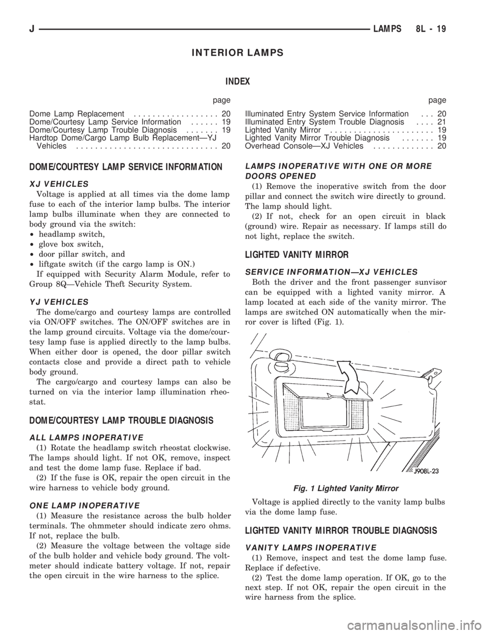
SERVICE INFORMATIONÐXJ VEHICLES
Both the driver and the front passenger sunvisor
can be equipped with a lighted vanity mirror. A
lamp located at each side of the vanity mirror. The
lamps are switched ON automatically when the mir-
ror cover is lifted (Fig. 1).
Voltage is applied directly to the vanity lamp bulbs
via the dome lamp fuse.
LIGHTED VANITY MIRROR TROUBLE DIAGNOSIS
VANITY LAMPS INOPERATIVE
(1) Remove, inspect and test the dome lamp fuse.
Replace if defective.
(2) Test the dome lamp operation. If OK, go to the
next step. If not OK, repair the open circuit in the
wire harness from the splice.
Fig. 1 Lighted Vanity Mirror
JLAMPS 8L - 19