1994 JEEP CHEROKEE fuse
[x] Cancel search: fusePage 503 of 1784
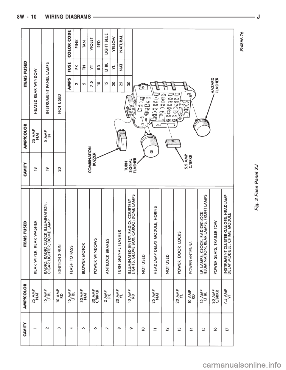
Fig. 2 Fuse Panel XJ
8W - 10 WIRING DIAGRAMSJ
Page 567 of 1784
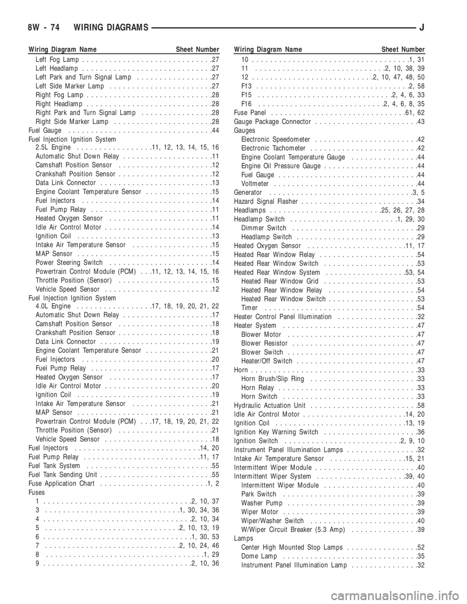
Wiring Diagram Name Sheet Number
Left Fog Lamp.............................27
Left Headlamp.............................27
Left Park and Turn Signal Lamp.................27
Left Side Marker Lamp.......................27
Right Fog Lamp............................28
Right Headlamp............................28
Right Park and Turn Signal Lamp................28
Right Side Marker Lamp......................28
Fuel Gauge................................44
Fuel Injection Ignition System
2.5L Engine.................11, 12, 13, 14, 15, 16
Automatic Shut Down Relay....................11
Camshaft Position Sensor.....................12
Crankshaft Position Sensor.....................12
Data Link Connector.........................13
Engine Coolant Temperature Sensor...............15
Fuel Injectors.............................14
Fuel Pump Relay...........................11
Heated Oxygen Sensor.......................11
Idle Air Control Motor........................14
Ignition Coil..............................13
Intake Air Temperature Sensor..................15
MAP Sensor..............................15
Power Steering Switch.......................14
Powertrain Control Module (PCM) . . .11, 12, 13, 14, 15, 16
Throttle Position (Sensor).....................15
Vehicle Speed Sensor........................12
Fuel Injection Ignition System
4.0L Engine.................17, 18, 19, 20, 21, 22
Automatic Shut Down Relay....................17
Camshaft Position Sensor.....................18
Crankshaft Position Sensor.....................18
Data Link Connector.........................19
Engine Coolant Temperature Sensor...............21
Fuel Injectors.............................20
Fuel Pump Relay...........................17
Heated Oxygen Sensor.......................17
Idle Air Control Motor........................20
Ignition Coil..............................19
Intake Air Temperature Sensor..................21
MAP Sensor..............................21
Powertrain Control Module (PCM) . . .17, 18, 19, 20, 21, 22
Throttle Position (Sensor).....................21
Vehicle Speed Sensor........................18
Fuel Injectors............................14, 20
Fuel Pump Relay..........................11, 17
Fuel Tank System............................55
Fuel Tank Sending Unit.........................55
Fuse Application Chart........................1,2
Fuses
1 .................................2,10,37
3 ..............................1,30,34,36
4 .................................2,10,34
5 ..............................2,10,13,19
6 .................................1,30,53
7 ..............................2,10,24,46
8 ...................................1,29
9 .................................2,10,36Wiring Diagram Name Sheet Number
10 ...................................1,31
11 .............................2,10,38,39
12 ...........................2,10,47,48,50
F13 ..................................2,58
F15 ..............................2,4,6,33
F16 ............................2,4,6,8,35
Fuse Panel..............................61, 62
Gauge Package Connector.......................43
Gauges
Electronic Speedometer.......................42
Electronic Tachometer........................42
Engine Coolant Temperature Gauge...............44
Engine Oil Pressure Gauge.....................44
Fuel Gauge...............................44
Voltmeter................................44
Generator................................3,5
Hazard Signal Flasher..........................34
Headlamps.........................25, 26, 27, 28
Headlamp Switch........................1,29,30
Dimmer Switch............................29
Headlamp Switch...........................29
Heated Oxygen Sensor......................11, 17
Heated Rear Window Relay......................54
Heated Rear Window Switch.....................53
Heated Rear Window System..................53, 54
Heated Rear Window Grid.....................53
Heated Rear Window Relay....................54
Heated Rear Window Switch....................53
Timer..................................54
Heater Control Panel Illumination..................32
Heater System..............................47
Blower Motor.............................47
Blower Resistor............................47
Blower Switch.............................47
Heater/Off Switch...........................47
Horn.....................................33
Horn Brush/Slip Ring........................33
Horn Relay...............................33
Horn Switch..............................33
Hydraulic Actuation Unit........................58
Idle Air Control Motor.......................14, 20
Ignition Coil.............................13, 19
Ignition Key Warning Switch.....................36
Ignition Switch..........................2,9,10
Instrument Panel Illumination Lamps................32
Intake Air Temperature Sensor.................15, 21
Intermittent Wiper Module.......................40
Intermittent Wiper System....................39, 40
Intermittent Wiper Module.....................40
Park Switch..............................39
Washer Pump.............................39
Wiper Motor..............................39
Wiper/Washer Switch........................40
W/Wiper Circuit Breaker (5.3 Amp)...............39
Lamps
Center High Mounted Stop Lamps................52
Dome Lamp..............................35
Instrument Panel Illumination Lamp...............32
8W - 74 WIRING DIAGRAMSJ
Page 643 of 1784
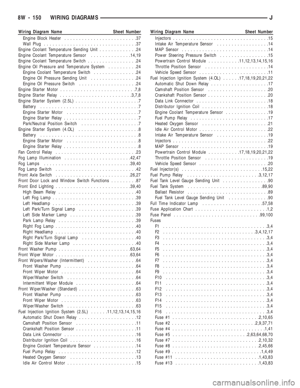
Wiring Diagram Name Sheet Number
Engine Block Heater.........................37
Wall Plug................................37
Engine Coolant Temperature Sending Unit.............24
Engine Coolant Temperature Sensor..............14,19
Engine Coolant Temperature Switch.................24
Engine Oil Pressure and Temperature System..........24
Engine Coolant Temperature Switch...............24
Engine Oil Pressure Sending Unit................24
Engine Oil Pressure Switch....................24
Engine Starter Motor..........................7,8
Engine Starter Relay.........................3,7,8
Engine Starter System (2.5L)......................7
Battery..................................7
Engine Starter Motor.........................7
Engine Starter Relay..........................7
Park/Neutral Position Switch....................7
Engine Starter System (4.OL).....................8
Battery..................................8
Engine Starter Motor.........................8
Engine Starter Relay..........................8
Fan Control Relay............................23
Fog Lamp Illumination.......................42,47
Fog Lamps..............................39,40
Fog Lamp Switch............................42
Front Axle Switch..........................26,27
Front Door Lock and Window Switch Functions.........87
Front End Lighting..........................39,40
High Beam Relay...........................40
Left Fog Lamp.............................39
Left Headlamp.............................39
Left Park/Turn Signal Lamp....................39
Left Side Marker Lamp.......................39
Park Lamp Relay...........................39
Right Fog Lamp............................40
Right Headlamp............................40
Right Park/Turn Signal Lamp...................40
Right Side Marker Lamp......................40
Front Washer Pump.........................63,64
Front Wiper Motor..........................63,64
Front Wipers/Washer (Intermittent).................64
Front Washer Pump.........................64
Front Wiper Motor..........................64
Wiper/Washer Switch........................64
Intermittent Wiper Module.....................64
Front Wiper/Washer (Standard)....................63
Front Washer Pump.........................63
Front Wiper Motor..........................63
Wiper/Washer Switch........................63
Fuel Injection Ignition System (2.5L)......11,12,13,14,15,16
Automatic Shut Down Relay....................12
Camshaft Position Sensor.....................11
Crankshaft Position Sensor.....................11
Data Link Connector.........................16
Distributor Ignition Coil.......................16
Engine Coolant Temperature Sensor...............14
Fuel Pump Relay...........................12
Heated Oxygen Sensor.......................13
Idle Air Control Motor........................15Wiring Diagram Name Sheet Number
Injectors.................................15
Intake Air Temperature Sensor..................14
MAP Sensor..............................14
Power Steering Pressure Switch.................15
Powertrain Control Module...........11,12,13,14,15,16
Throttle Position Sensor......................14
Vehicle Speed Sensor........................11
Fuel Injection Ignition System (4.OL)......17,18,19,20,21,22
Automatic Shut Down Relay....................17
Camshaft Position Sensor.....................20
Crankshaft Position Sensor.....................20
Data Link Connector.........................18
Distributor Ignition Coil.......................18
Engine Coolant Temperature Sensor...............19
Fuel Pump Relay...........................17
Heated Oxygen Sensor.......................21
Idle Air Control Motor........................22
Intake Air Temperature Sensor..................19
Injectors.................................22
MAP Sensor..............................19
Powertrain Control Module...........17,18,19,20,21,22
Throttle Position Sensor......................19
Vehicle Speed Sensor........................20
Fuel Injector(s)............................15,22
Fuel Pump Relay.........................3,12,17
Fuel Tank Level Gauge Sending Unit................90
Fuel Tank System..........................89,90
Ballast Resistor............................89
Fuel Tank Level Gauge Sending Unit..............90
Full Time Indicator Lamp.....................57,58
Fuse Application Chart.........................1,2
Fuse Panel..............................99,100
Fuses
F1 ....................................3,4
F2 ................................3,4,12,17
F3 ....................................3,4
F4 ....................................3,4
F5 ....................................3,4
F6 ....................................3,4
F7 ....................................3,4
F8 ....................................3,4
F9 ....................................3,4
F10 ...................................3,4
F11 ...................................3,4
F12 ...................................3,4
F13 ...................................3,4
F14 ...................................3,4
F15 ...................................3,4
F16 ...................................3,4
Fuse #1..............................2,10,65
Fuse #2.............................2,9,37,71
Fuse #4................................1,41
Fuse #5..........................2,63,64,68,70
Fuse #7..............................2,10,32
Fuse #8..............................2,45,66
Fuse #9...............................1,4,49
Fuse #11.............................1,43,83
Fuse #13.............................1,43,83
8W - 150 WIRING DIAGRAMSJ
Page 644 of 1784
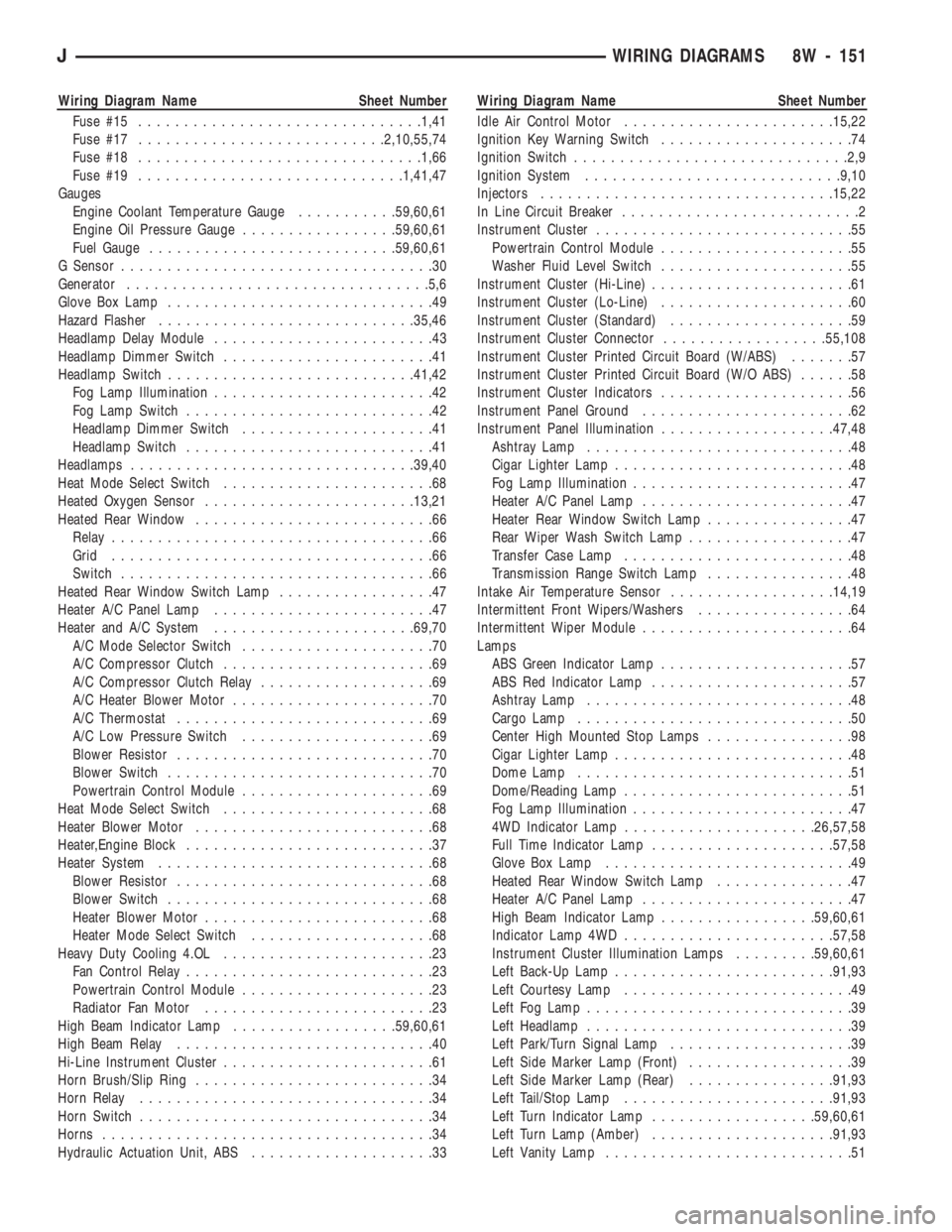
Wiring Diagram Name Sheet Number
Fuse #15...............................1,41
Fuse #17...........................2,10,55,74
Fuse #18...............................1,66
Fuse #19.............................1,41,47
Gauges
Engine Coolant Temperature Gauge...........59,60,61
Engine Oil Pressure Gauge.................59,60,61
Fuel Gauge...........................59,60,61
G Sensor..................................30
Generator.................................5,6
Glove Box Lamp.............................49
Hazard Flasher............................35,46
Headlamp Delay Module........................43
Headlamp Dimmer Switch.......................41
Headlamp Switch...........................41,42
Fog Lamp Illumination........................42
Fog Lamp Switch...........................42
Headlamp Dimmer Switch.....................41
Headlamp Switch...........................41
Headlamps...............................39,40
Heat Mode Select Switch.......................68
Heated Oxygen Sensor.......................13,21
Heated Rear Window..........................66
Relay...................................66
Grid...................................66
Switch..................................66
Heated Rear Window Switch Lamp.................47
Heater A/C Panel Lamp........................47
Heater and A/C System......................69,70
A/C Mode Selector Switch.....................70
A/C Compressor Clutch.......................69
A/C Compressor Clutch Relay...................69
A/C Heater Blower Motor......................70
A/C Thermostat............................69
A/C Low Pressure Switch.....................69
Blower Resistor............................70
Blower Switch.............................70
Powertrain Control Module.....................69
Heat Mode Select Switch.......................68
Heater Blower Motor..........................68
Heater,Engine Block...........................37
Heater System..............................68
Blower Resistor............................68
Blower Switch.............................68
Heater Blower Motor.........................68
Heater Mode Select Switch....................68
Heavy Duty Cooling 4.OL.......................23
Fan Control Relay...........................23
Powertrain Control Module.....................23
Radiator Fan Motor.........................23
High Beam Indicator Lamp..................59,60,61
High Beam Relay............................40
Hi-Line Instrument Cluster.......................61
Horn Brush/Slip Ring..........................34
Horn Relay................................34
Horn Switch................................34
Horns....................................34
Hydraulic Actuation Unit, ABS....................33Wiring Diagram Name Sheet Number
Idle Air Control Motor.......................15,22
Ignition Key Warning Switch.....................74
Ignition Switch..............................2,9
Ignition System............................9,10
Injectors................................15,22
In Line Circuit Breaker..........................2
Instrument Cluster............................55
Powertrain Control Module.....................55
Washer Fluid Level Switch.....................55
Instrument Cluster (Hi-Line)......................61
Instrument Cluster (Lo-Line).....................60
Instrument Cluster (Standard)....................59
Instrument Cluster Connector..................55,108
Instrument Cluster Printed Circuit Board (W/ABS).......57
Instrument Cluster Printed Circuit Board (W/O ABS)......58
Instrument Cluster Indicators.....................56
Instrument Panel Ground.......................62
Instrument Panel Illumination...................47,48
Ashtray Lamp.............................48
Cigar Lighter Lamp..........................48
Fog Lamp Illumination........................47
Heater A/C Panel Lamp.......................47
Heater Rear Window Switch Lamp................47
Rear Wiper Wash Switch Lamp..................47
Transfer Case Lamp.........................48
Transmission Range Switch Lamp................48
Intake Air Temperature Sensor..................14,19
Intermittent Front Wipers/Washers.................64
Intermittent Wiper Module.......................64
Lamps
ABS Green Indicator Lamp.....................57
ABS Red Indicator Lamp......................57
Ashtray Lamp.............................48
Cargo Lamp..............................50
Center High Mounted Stop Lamps................98
Cigar Lighter Lamp..........................48
Dome Lamp..............................51
Dome/Reading Lamp.........................51
Fog Lamp Illumination........................47
4WD Indicator Lamp.....................26,57,58
Full Time Indicator Lamp....................57,58
Glove Box Lamp...........................49
Heated Rear Window Switch Lamp...............47
Heater A/C Panel Lamp.......................47
High Beam Indicator Lamp.................59,60,61
Indicator Lamp 4WD.......................57,58
Instrument Cluster Illumination Lamps.........59,60,61
Left Back-Up Lamp........................91,93
Left Courtesy Lamp.........................49
Left Fog Lamp.............................39
Left Headlamp.............................39
Left Park/Turn Signal Lamp....................39
Left Side Marker Lamp (Front)..................39
Left Side Marker Lamp (Rear)................91,93
Left Tail/Stop Lamp.......................91,93
Left Turn Indicator Lamp..................59,60,61
Left Turn Lamp (Amber)....................91,93
Left Vanity Lamp...........................51
JWIRING DIAGRAMS 8W - 151
Page 765 of 1784
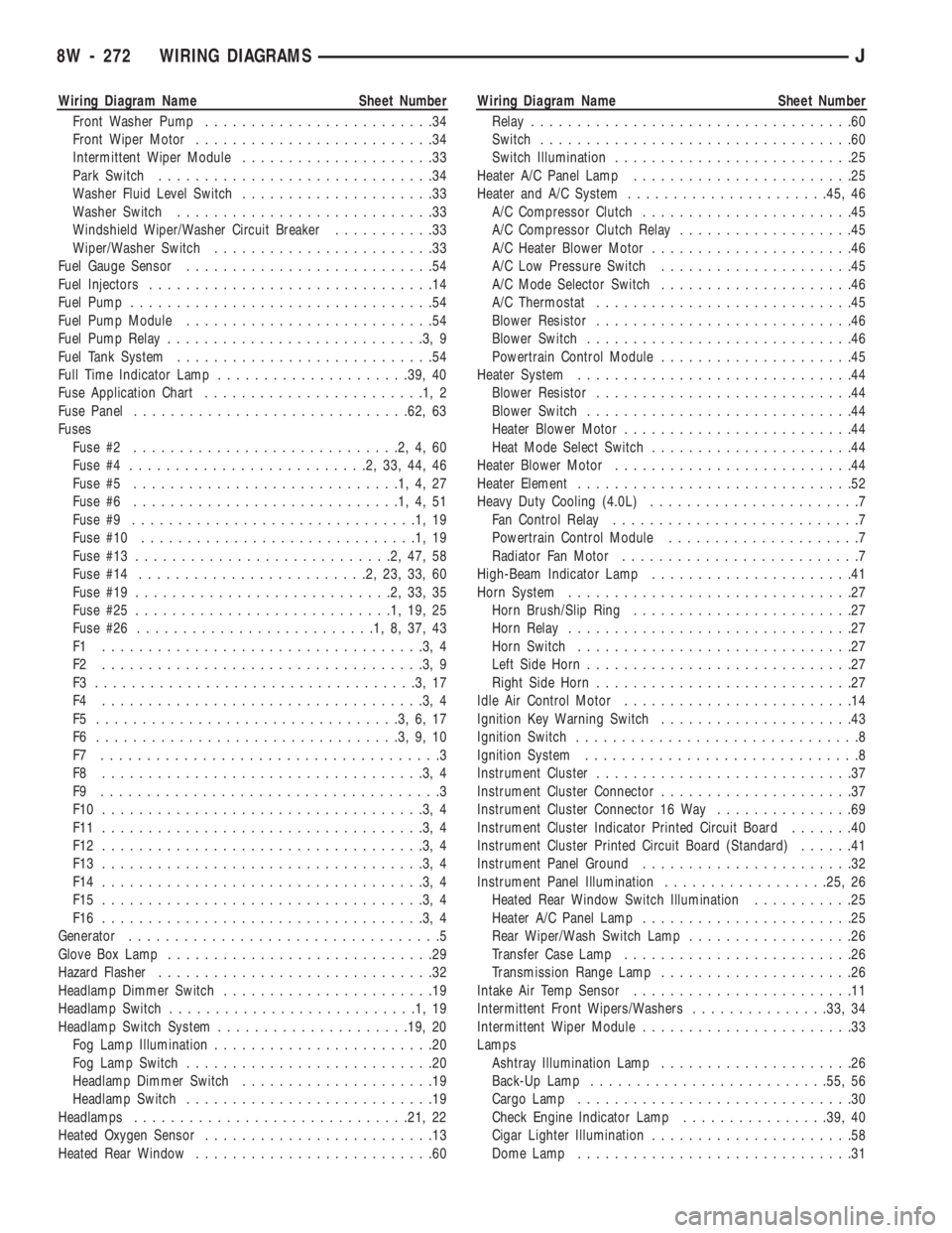
Wiring Diagram Name Sheet Number
Front Washer Pump.........................34
Front Wiper Motor..........................34
Intermittent Wiper Module.....................33
Park Switch..............................34
Washer Fluid Level Switch.....................33
Washer Switch............................33
Windshield Wiper/Washer Circuit Breaker...........33
Wiper/Washer Switch........................33
Fuel Gauge Sensor...........................54
Fuel Injectors...............................14
Fuel Pump.................................54
Fuel Pump Module...........................54
Fuel Pump Relay............................3,9
Fuel Tank System............................54
Full Time Indicator Lamp.....................39, 40
Fuse Application Chart........................1,2
Fuse Panel..............................62, 63
Fuses
Fuse #2.............................2,4,60
Fuse #4..........................2,33,44,46
Fuse #5.............................1,4,27
Fuse #6.............................1,4,51
Fuse #9...............................1,19
Fuse #10..............................1,19
Fuse #13............................2,47,58
Fuse #14.........................2,23,33,60
Fuse #19............................2,33,35
Fuse #25............................1,19,25
Fuse #26..........................1,8,37,43
F1 ...................................3,4
F2 ...................................3,9
F3 ...................................3,17
F4 ...................................3,4
F5 .................................3,6,17
F6 .................................3,9,10
F7 .....................................3
F8 ...................................3,4
F9 .....................................3
F10 ...................................3,4
F11 ...................................3,4
F12 ...................................3,4
F13 ...................................3,4
F14 ...................................3,4
F15 ...................................3,4
F16 ...................................3,4
Generator..................................5
Glove Box Lamp.............................29
Hazard Flasher..............................32
Headlamp Dimmer Switch.......................19
Headlamp Switch...........................1,19
Headlamp Switch System.....................19, 20
Fog Lamp Illumination........................20
Fog Lamp Switch...........................20
Headlamp Dimmer Switch.....................19
Headlamp Switch...........................19
Headlamps..............................21, 22
Heated Oxygen Sensor.........................13
Heated Rear Window..........................60Wiring Diagram Name Sheet Number
Relay...................................60
Switch..................................60
Switch Illumination..........................25
Heater A/C Panel Lamp........................25
Heater and A/C System......................45, 46
A/C Compressor Clutch.......................45
A/C Compressor Clutch Relay...................45
A/C Heater Blower Motor......................46
A/C Low Pressure Switch.....................45
A/C Mode Selector Switch.....................46
A/C Thermostat............................45
Blower Resistor............................46
Blower Switch.............................46
Powertrain Control Module.....................45
Heater System..............................44
Blower Resistor............................44
Blower Switch.............................44
Heater Blower Motor.........................44
Heat Mode Select Switch......................44
Heater Blower Motor..........................44
Heater Element..............................52
Heavy Duty Cooling (4.0L).......................7
Fan Control Relay...........................7
Powertrain Control Module.....................7
Radiator Fan Motor..........................7
High-Beam Indicator Lamp......................41
Horn System...............................27
Horn Brush/Slip Ring........................27
Horn Relay...............................27
Horn Switch..............................27
Left Side Horn.............................27
Right Side Horn............................27
Idle Air Control Motor.........................14
Ignition Key Warning Switch.....................43
Ignition Switch...............................8
Ignition System..............................8
Instrument Cluster............................37
Instrument Cluster Connector.....................37
Instrument Cluster Connector 16 Way...............69
Instrument Cluster Indicator Printed Circuit Board.......40
Instrument Cluster Printed Circuit Board (Standard)......41
Instrument Panel Ground.......................32
Instrument Panel Illumination..................25, 26
Heated Rear Window Switch Illumination...........25
Heater A/C Panel Lamp.......................25
Rear Wiper/Wash Switch Lamp..................26
Transfer Case Lamp.........................26
Transmission Range Lamp.....................26
Intake Air Temp Sensor........................11
Intermittent Front Wipers/Washers...............33, 34
Intermittent Wiper Module.......................33
Lamps
Ashtray Illumination Lamp.....................26
Back-Up Lamp..........................55, 56
Cargo Lamp..............................30
Check Engine Indicator Lamp................39, 40
Cigar Lighter Illumination......................58
Dome Lamp..............................31
8W - 272 WIRING DIAGRAMSJ
Page 1268 of 1784
The valve body solenoids are controlled by signals
from the transmission control module (TCM). Signal
sequence is determined by vehicle speed and throttle
position.
Fourth gear is an 0.75:1 ratio overdrive range.
First, second, third and reverse gear are conventional
ranges. Third gear ratio is 1:1. A separate planetary
gear set provides overdrive operation in fourth gear.
TRANSMISSION RANGES AND SHIFT LEVER
POSITIONS
The AW-4 transmission has six ranges and shift le-
ver positions. Park, Reverse and Neutral are conven-
tional and mechanically operated. The 1-2, 3 and D
ranges provide electronically controlled shifting.
The 1-2 position provides first and second gear
only. The 3 position provides first, second and third
gear.
The D range provides first through fourth gear.
Overdrive fourth gear range is available only when
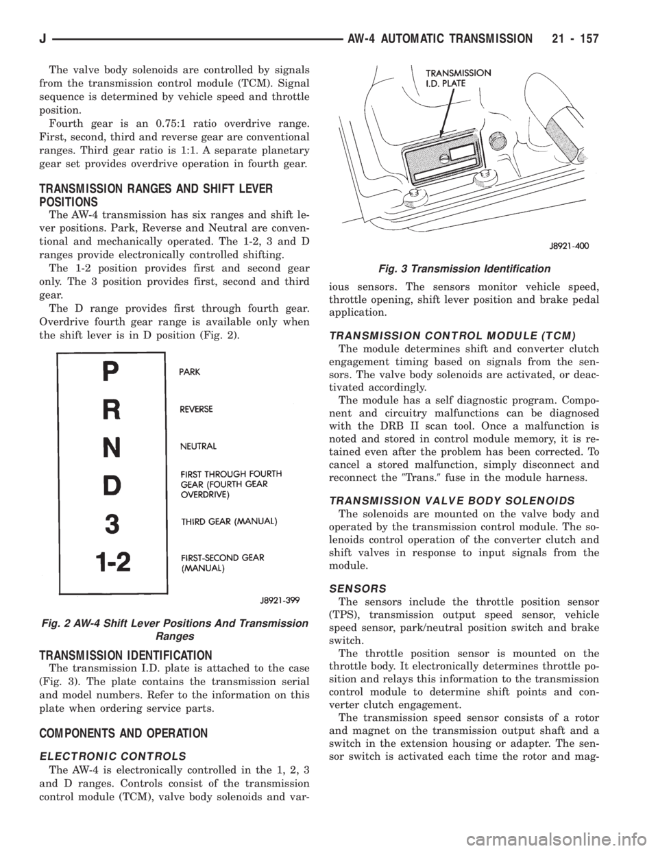
the shift lever is in D position (Fig. 2).
TRANSMISSION IDENTIFICATION
The transmission I.D. plate is attached to the case
(Fig. 3). The plate contains the transmission serial
and model numbers. Refer to the information on this
plate when ordering service parts.
COMPONENTS AND OPERATION
ELECTRONIC CONTROLS
The AW-4 is electronically controlled in the 1, 2, 3
and D ranges. Controls consist of the transmission
control module (TCM), valve body solenoids and var-ious sensors. The sensors monitor vehicle speed,
throttle opening, shift lever position and brake pedal
application.
TRANSMISSION CONTROL MODULE (TCM)
The module determines shift and converter clutch
engagement timing based on signals from the sen-
sors. The valve body solenoids are activated, or deac-
tivated accordingly.
The module has a self diagnostic program. Compo-
nent and circuitry malfunctions can be diagnosed
with the DRB II scan tool. Once a malfunction is
noted and stored in control module memory, it is re-
tained even after the problem has been corrected. To
cancel a stored malfunction, simply disconnect and
reconnect the9Trans.9fuse in the module harness.
TRANSMISSION VALVE BODY SOLENOIDS
The solenoids are mounted on the valve body and
operated by the transmission control module. The so-
lenoids control operation of the converter clutch and
shift valves in response to input signals from the
module.
SENSORS
The sensors include the throttle position sensor
(TPS), transmission output speed sensor, vehicle
speed sensor, park/neutral position switch and brake
switch.
The throttle position sensor is mounted on the
throttle body. It electronically determines throttle po-
sition and relays this information to the transmission
control module to determine shift points and con-
verter clutch engagement.
The transmission speed sensor consists of a rotor
and magnet on the transmission output shaft and a
switch in the extension housing or adapter. The sen-
sor switch is activated each time the rotor and mag-
Fig. 2 AW-4 Shift Lever Positions And Transmission
Ranges
Fig. 3 Transmission Identification
JAW-4 AUTOMATIC TRANSMISSION 21 - 157
Page 1279 of 1784
(2) Verify transmission throttle cable operation.
Repair or replace cable if necessary.
(3) Check engine throttle operation. Operate accel-
erator pedal and observe injector throttle plate move-
ment. Adjust linkage if throttle plate does not reach
wide open position.
(4) Check transmission fluid level when fluid is at
normal operating temperature. Start engine. Shift
transmission through all gear ranges then back to
Neutral. Correct level is to Full or Add mark on dip-
stick with engine at curb idle speed.
(5) Check and adjust park/neutral position switch
if necessary.
(6) Check throttle position sensor adjustment and
operation. Adjust the sensor if necessary.
MANUAL SHIFTING TEST
(1) This test determines if problem is related to
mechanical or electrical component.
(2) Stop engine and disconnect transmission con-
trol module or module fuse.
(3) Road test vehicle. Shift transmission into each
gear range. Transmission should operate as follows:
²lock in Park
²back up in Reverse
²not move in Neutral
²provide first gear only with shift lever in 1-2 posi-
tion
²operate in third gear only with shift lever in 3 po-
sition
²operate in overdrive fourth gear in D position
(4) If transmission operates as described, proceed
to next step. However, if forward gear ranges were
difficult to distinguish (all feel the same), or vehicle
would not back up, refer to diagnosis charts. Do not
perform stall or time lag tests.
CAUTION: Do not overspeed the engine during the
next test step. Ease off the throttle and allow the
vehicle to slow before downshifting.
(5) Continue road test. Manually downshift trans-
mission from D to 3, and from 3 to 1-2 position. Then
manually upshift transmission through forward
ranges again.
(6) If transmission operation is OK, perform stall,
time lag and pressure tests. If transmission shifting
problem is encountered, refer to diagnosis charts.
(7) If a problem still exists, continue testing with
DRB II scan tool.
HYDRAULIC PRESSURE TEST
PRESSURE TEST PROCEDURE
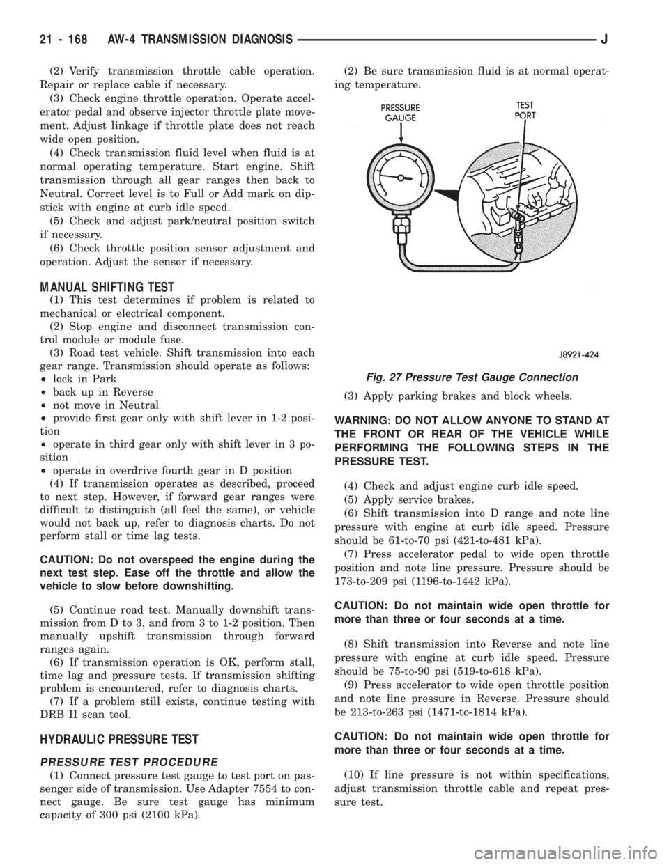
(1) Connect pressure test gauge to test port on pas-
senger side of transmission. Use Adapter 7554 to con-
nect gauge. Be sure test gauge has minimum
capacity of 300 psi (2100 kPa).(2) Be sure transmission fluid is at normal operat-
ing temperature.
(3) Apply parking brakes and block wheels.
WARNING: DO NOT ALLOW ANYONE TO STAND AT
THE FRONT OR REAR OF THE VEHICLE WHILE
PERFORMING THE FOLLOWING STEPS IN THE
PRESSURE TEST.
(4) Check and adjust engine curb idle speed.
(5) Apply service brakes.
(6) Shift transmission into D range and note line
pressure with engine at curb idle speed. Pressure
should be 61-to-70 psi (421-to-481 kPa).
(7) Press accelerator pedal to wide open throttle
position and note line pressure. Pressure should be
173-to-209 psi (1196-to-1442 kPa).
CAUTION: Do not maintain wide open throttle for
more than three or four seconds at a time.
(8) Shift transmission into Reverse and note line
pressure with engine at curb idle speed. Pressure
should be 75-to-90 psi (519-to-618 kPa).
(9) Press accelerator to wide open throttle position
and note line pressure in Reverse. Pressure should
be 213-to-263 psi (1471-to-1814 kPa).
CAUTION: Do not maintain wide open throttle for
more than three or four seconds at a time.
(10) If line pressure is not within specifications,
adjust transmission throttle cable and repeat pres-
sure test.
Fig. 27 Pressure Test Gauge Connection
21 - 168 AW-4 TRANSMISSION DIAGNOSISJ
Page 1544 of 1784
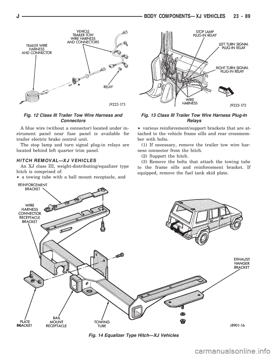
A blue wire (without a connector) located under in-
strument panel near fuse panel is available for
trailer electric brake control unit.
The stop lamp and turn signal plug-in relays are
located behind left quarter trim panel.
HITCH REMOVALÐXJ VEHICLES
An XJ class III, weight-distributing/equalizer type
hitch is comprised of:
²a towing tube with a ball mount receptacle, and²various reinforcement/support brackets that are at-
tached to the vehicle frame sills and rear crossmem-
ber with bolts.
(1) If necessary, remove the trailer tow wire har-
ness connector from the hitch.
(2) Support the hitch.
(3) Remove the bolts that attach the towing tube
to the frame sills and reinforcement bracket. If
equipped, remove the fuel tank skid plate.
Fig. 14 Equalizer Type HitchÐXJ Vehicles
Fig. 12 Class III Trailer Tow Wire Harness and
ConnectorsFig. 13 Class III Trailer Tow Wire Harness Plug-In
Relays
JBODY COMPONENTSÐXJ VEHICLES 23 - 89