1994 JEEP CHEROKEE check oil
[x] Cancel search: check oilPage 149 of 1784
Use Mopar Multi Mileage grease to lubricate drum
brake pivot pins and rear brakeshoe contact points
on the support plates. Use GE 661, or Dow 111 sili-
cone grease on caliper bushings and mounting bolts.
Use fresh brake fluid or Mopar brake cleaner to
clean or flush brake system components. These are
the only cleaning materials recommended.
CAUTION: Never use gasoline, kerosene, methyl or
isopropyl alcohol, paint thinner, or any fluid con-
taining mineral oil to clean the system components.
These fluids damage rubber cups and seals. If sys-
tem contamination is suspected, check the fluid for
dirt, discoloration, or separation into distinct layers.
Drain and flush the system with new brake fluid if
contamination is suspected.
JEEP BODY CODE LETTERS
The body/model identification code letters for Jeep
vehicles are as follows:
²Code letters XJ: Cherokee
²Code letters YJ: Wrangler/YJ
The code letters are used throughout this group to
simplify model identification and component applica-
tion.
BRAKE SAFETY PRECAUTIONS
WARNING: ALTHOUGH FACTORY INSTALLED
BRAKELINING ON JEEP VEHICLES IS MADE FROM
ASBESTOS FREE MATERIALS, SOME AFTER MARKET
BRAKELINING MAY CONTAIN ASBESTOS. THIS
SHOULD BE TAKEN INTO ACCOUNT WHEN REPAIR-
ING A VEHICLE WITH PRIOR BRAKE SERVICE. WEAR
A RESPIRATOR WHEN CLEANING BRAKE COMPO-
NENTS AS ASBESTOS FIBERS CAN BE A HEALTH
HAZARD. NEVER CLEAN WHEEL BRAKE COMPO-
NENTS WITH COMPRESSED AIR. USE A VACUUM
CLEANER SPECIFICALLY DESIGNED FOR REMOVING
BRAKE DUST. IF A VACUUM CLEANER IS NOT AVAIL-
ABLE, CLEAN THE PARTS WITH WATER DAMPENED
SHOP RAGS. DO NOT CREATE DUST BY SANDING
BRAKELINING. DISPOSE OF ALL DUST AND DIRT
SUSPECTED OF CONTAINING ASBESTOS FIBERS IN
SEALED BAGS OR CONTAINERS. FOLLOW ALL REC-
OMMENDED SAFETY PRACTICES PRESCRIBED BY
THE OCCUPATIONAL SAFETY AND HEALTH ADMINIS-
TRATION (OSHA) AND THE ENVIRONMENTAL PRO-
TECTION AGENCY (EPA), FOR HANDLING AND
DISPOSAL OF PRODUCTS CONTAINING ASBESTOS.
5 - 2 BRAKESJ
Page 154 of 1784
SERVICE BRAKE DIAGNOSIS
INDEX
page page
Component Inspection...................... 8
Diagnosing Parking Brake Problems.......... 10
Diagnosing Service Brake Problems........... 8
Diagnosis Procedures...................... 7
General Information........................ 7Master Cylinder/Power Booster Test.......... 11
Power Booster Check Valve Test............ 11
Power Booster Vacuum Test................ 12
Preliminary Brake Check.................... 7
Road Testing............................ 7
GENERAL INFORMATION
The diagnosis information in this section covers
service brake components which include:
²disc brake calipers
²disc brakeshoes
²drum brake wheel cylinders
²drum brakeshoes and brake drums
²drum brake support plates
²parking brake mechanism
²master cylinder/combination valve
²vacuum power brake booster
²brake pedal and brakelight switch
²brake warning light
DIAGNOSIS PROCEDURES
Service brake diagnosis involves determining if a
problem is related to a mechanical, hydraulic or vac-
uum operated component. A preliminary brake
check, followed by road testing and component in-
spection are needed to determine a problem cause.
Road testing will either verify proper brake opera-
tion or confirm the existence of a problem. Compo-
nent inspection will, in most cases, identify the
actual part responsible for a problem.
The first diagnosis step is the preliminary brake
check. This involves inspecting fluid level, parking
brake action, wheel and tire condition, checking for
obvious leaks or component damage and testing
brake pedal response. A road test will confirm or
deny the existence of a problem. The final diagnosis
procedure involves road test analysis and a visual in-
spection of brake components.
PRELIMINARY BRAKE CHECK
(1) If amber antilock light is illuminated, refer to
Antilock Brake System Diagnosis. However, if red
warning light is illuminated, or if neither warning
light is illuminated, continue with diagnosis.
(2) Check condition of tires and wheels. Damaged
wheels and worn, damaged, or underinflated tires
can cause pull, shudder, tramp and a condition simi-
lar to grab.
(3) If complaint was based on noise when braking,
check suspension components. Jounce front and rearof vehicle and listen for noise that might be caused
by loose, worn, or damaged suspension or steering
components.
(4) Inspect brake fluid level:
(a) If vehicle has one-piece master cylinder, fluid
level should be to 6 mm (1/4 in.) of reservoir rim. If
vehicle two-piece, removable reservoir, correct level
is to top of indicator rings in reservoir.
(b) On models with ABS brakes, preferred level
is to MAX mark on reservoir. Acceptable level is
between MAX and MIN marks.
(c) Remember that fluid level in the front and
rear reservoir compartments will decrease in pro-
portion to normal lining wear. However, if fluid
level is abnormally low, look for leaks at calipers,
wheel cylinders, brakelines and master cylinder.
(5) Inspect brake fluid condition:
(a) Fluid should be reasonably clear and free of
foreign material.Note that brake fluid tends to
darken over time. This is normal and should
not be mistaken for contamination. If fluid is
clear of foreign material, it is OK.
(b) If fluid is highly discolored, or appears to con-
tain foreign material, drain out a sample with a
clean suction gun. Pour sample in a glass container
and note condition.
(c) If fluid separates into layers, obviously con-
tains oil, or a substance other than brake fluid,
system seals and cups will have to be replaced and
hydraulic system flushed.
(6) Check parking brake operation. Verify free
movement and full release of cables and foot pedal or
hand lever. Also note if vehicle was being operated
with parking brake partially applied.
(7) Check brake pedal operation. Verify that pedal
does not bind and has adequate free play. If pedal
lacks free play, check pedal and power booster for be-
ing loose or for bind condition. Do not road test until
condition is corrected.
(8) If components inspected look OK, road test the
vehicle.
ROAD TESTING
(1) If amber warning light is illuminated, problem
is with antilock system component. Refer to Antilock
Brake System Diagnosis.
JBRAKES 5 - 7
Page 160 of 1784
BRAKE BLEEDINGÐBRAKE FLUID AND LEVELÐBRAKELINES AND HOSES
INDEX
page page
Brake BleedingÐXJ/YJ with ABS Brakes....... 14
Brake BleedingÐXJ/YJ with Standard Brakes . . . 13
Brake Fluid Contamination.................. 13
Brake Fluid Level........................ 13Brakeline Charts......................... 15
Brakelines and Hoses..................... 15
Combination Valve....................... 15
Recommended Brake Fluid................. 13
RECOMMENDED BRAKE FLUID
The only brake fluid recommended for Jeep vehi-
cles with standard or antilock brakes, is Mopar brake
fluid, or an equivalent fluid meeting SAE J1703 and
DOT 3 standards.
Use new brake fluid only to top off the master
cylinder or refill the system. Never use re-
claimed fluid, fluid not meeting the SAE/DOT
standards or fluid from an unsealed container.
Do not use fluid from any container that has
been left open for any length of time. Fluid in
open containers can absorb moisture.
BRAKE FLUID LEVEL
Always clean the master cylinder and cover before
checking fluid level. If not cleaned, dirt from the
cover could enter the fluid. Also check the cover seal
and replace it if torn or distorted.
Correct fluid level is to within 6 mm (1/4 in.) of the
reservoir rim, or to the fill mark on models with a
plastic reservoir. Refer to the Antilock Brake section
for fluid levels on models equipped with ABS brakes.
BRAKE FLUID CONTAMINATION
Oil in the fluid will cause brake system rubber
seals to soften and swell. The seals may also become
porous and begin to deteriorate.
If fluid contamination is suspected, drain off a sam-
ple from the master cylinder. A suction gun or simi-
lar device can be used for this purpose.
Empty the drained fluid into a glass container.
Contaminants in the fluid will cause the fluid to sep-
arate into distinct layers. If contamination has oc-
curred, the system rubber seals, hoses and cups must
be replaced and the system thoroughly flushed with
clean brake fluid.
BRAKE BLEEDINGÐXJ/YJ WITH STANDARD
BRAKES
Use Mopar DOT 3 brake fluid, or an equivalent
meeting SAE/DOT standards J1703-F and DOT 3, to
fill and bleed the system.
On standard brake models, bleeding can be per-
formed either manually or with pressure equipment.
However, if pressure equipment is used, it will be
necessary to hold the front brake metering valveopen in order to bleed the front brakes. The valve
can be held open with a tension clip tool or by hand.
It will also be necessary that a suitable size pressure
tank hose adapter be available for use on the master
cylinder.
MANUAL BLEEDING PROCEDURE
(1) If master cylinder has been overhauled or a
new cylinder will be installed, bleed cylinder on
bench before installation. This shortens time needed
to bleed system and ensures proper cylinder opera-
tion.
(2) Wipe master cylinder reservoir and cap clean
with shop towels.
(3) Remove cover and fill master cylinder reservoir
with Mopar, or equivalent DOT 3 brake fluid.
(4) Open all caliper and wheel cylinder bleed
screws.
(5) Close bleed screws after fluid begins flowing
from each bleed screw.
(6) Top off master cylinder reservoir again.
(7) Use following bleed sequence:
²master cylinder
²right rear
²left rear
²right front
²left front
(8) Observe following brake bleeding precautions:
²Do not pump brake pedal at any time while bleed-
ing. Air in system will be compressed into small bub-
bles that are distributed throughout hydraulic
system. This will make a second and third bleeding
operation necessary.
²Bleed only one wheel brake unit at a time and use
a bleed hose to bleed each wheel brake unit (Fig. 7).
²Attach one end of bleed hose to bleed screw and in-
sert opposite end in glass container partially filled
with brake fluid (Fig. 7). Glass container makes it
easier to see air bubbles as they exit the bleed hose.
²Be sure end of bleed hose is immersed in fluid. Im-
mersing hose end in fluid prevents air from being
drawn back into cylinder and brakeline.
(9) Bleed master cylinder first. Have helper oper-
ate brake pedal while bleeding each master cylinder
fluid outlet line.
JBRAKES 5 - 13
Page 218 of 1784
CLUTCH DIAGNOSIS
INDEX
page page
Clutch Problem Causes..................... 3
General Diagnosis Information................ 3Inspection and Diagnosis Charts.............. 4
GENERAL DIAGNOSIS INFORMATION
Unless the cause of a clutch problem is obvious, ac-
curate problem diagnosis will usually require a road
test to confirm a problem. Component inspection will
then be required to determine the actual problem
cause.
During a road test, drive the vehicle at normal
speeds. Shift the transmission through all gear
ranges and observe clutch action. If chatter, grab,
slip, or improper release is experienced, remove and
inspect the clutch components. However, if the prob-
lem is noise or hard shifting, further diagnosis may
be needed as the transmission or another driveline
component may be at fault. Careful observation dur-
ing the test will help narrow the problem area.
CLUTCH PROBLEM CAUSES
CONTAMINATION
Fluid contamination is a frequent cause of clutch
malfunctions. Oil, water, or clutch fluid on the clutch
contact surfaces will cause faulty operation. The
usual result is chatter, slip and grab.
During inspection, note if any components are con-
taminated with oil, hydraulic fluid, or water/road
splash.
Oil contamination indicates a leak at either the
rear main seal or transmission input shaft. Oil leak-
age produces a residue of oil on the housing interior
and on the clutch cover and flywheel. Heat buildup
caused by slippage between the cover, disc and fly-
wheel, can sometimes bake the oil residue onto the
components. The glaze-like residue ranges in color
from amber to black.
Road splash contamination means dirt/water is en-
tering the clutch housing due to loose bolts, housing
cracks, or through hydraulic line openings. Driving
through deep water puddles can force water/road
splash into the housing through such openings.
Clutch fluid leaks are from loose or damaged slave
cylinder fluid lines and connecting fittings. However,
clutch fluid leaks will usually be noted and corrected
before severe contamination occurs.
CLUTCH MISALIGNMENT
Clutch components must be in proper alignment
with the crankshaft and transmission input shaft.Misalignment caused by excessive runout or warpage
of any clutch component will cause grab, chatter and
improper clutch release.
Flywheel Runout
Check flywheel runout whenever misalignment is
suspected. Flywheel runout should not exceed 0.08
mm (0.003 in.). Measure runout at the outer edge of
the flywheel face with a dial indicator. Mount the in-
dicator on a stud installed in place of one of the fly-
wheel bolts.
Common causes of runout are:
²heat warpage
²improper machining
²incorrect bolt tightening
²improper seating on crankshaft flange shoulder
²foreign material on crankshaft flange
Flywheel machining is not recommended. The fly-
wheel clutch surface is machined to a unique contour
and machining will negate this feature. However,
minor flywheel scoring can be cleaned up by hand
with 180 grit emery, or with surface grinding equip-
ment. Remove only enough material to reduce scor-
ing (approximately 0.001 - 0.003 in.). Heavy stock
removal isnot recommended.Replace the flywheel
if scoring is severe and deeper than 0.076 mm (0.003
in.). Excessive stock removal can result in flywheel
cracking or warpage after installation; it can also
weaken the flywheel and interfere with proper clutch
release.
Clean the crankshaft flange before mounting the
flywheel. Dirt and grease on the flange surface may
cock the flywheel causing excessive runout. Use new
bolts when remounting a flywheel and secure the
bolts with Mopar Lock And Seal. Tighten flywheel
bolts to specified torque only. Overtightening can dis-
tort the flywheel hub causing runout.
Clutch Cover And Disc Runout
Check the clutch disc before installation. Axial
(face) runout of anewdisc should not exceed 0.50
mm (0.020 in.). Measure runout about 6 mm (1/4 in.)
from the outer edge of the disc facing. Obtain an-
other disc if runout is excessive.
Check condition of the clutch before installation. A
warped cover or diaphragm spring will cause grab
and incomplete release or engagement. Be careful
JCLUTCH DIAGNOSIS 6 - 3
Page 242 of 1784
SERVICE PROCEDURES
INDEX
page page
Coolant................................ 15
Coolant Reserve/Overflow System............ 19
Cooling System Cleaning/Reverse Flushing..... 17
Cooling System Fans..................... 26
Cooling System Hoses.................... 26
Draining Cooling System................... 16
Radiator Pressure Cap.................... 20
Radiators............................... 22Refilling Cooling System................... 17
Testing Cooling System for Leaks............ 18
Thermostat............................. 13
Transmission Oil Coolers................... 29
Water Pump Tests........................ 9
Water PumpsÐGeneral Information............ 9
Water PumpsÐRemoval/Installation........... 10
WATER PUMPSÐGENERAL INFORMATION
A centrifugal water pump circulates coolant
through the water jackets, passages, intake manifold,
radiator core, cooling system hoses and heater core.
The pump is driven from the engine crankshaft by a
drive belt on all engines.
The water pump impeller is pressed onto the rear
of a shaft that rotates in bearings pressed into the
housing. The housing has a small hole to allow seep-
age to escape. The water pump seals are lubricated
by the antifreeze in the coolant mixture. No addi-
tional lubrication is necessary.
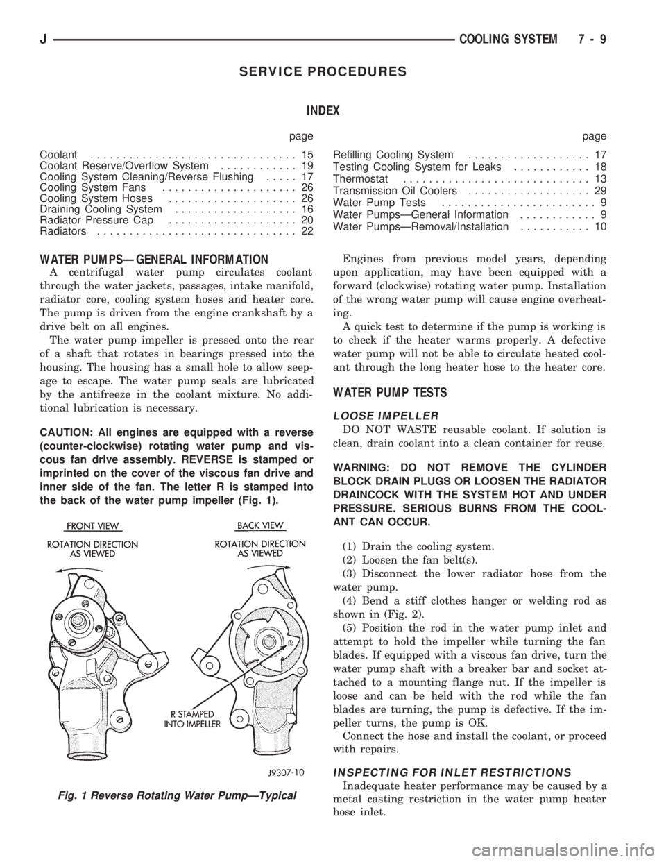
CAUTION: All engines are equipped with a reverse
(counter-clockwise) rotating water pump and vis-
cous fan drive assembly. REVERSE is stamped or
imprinted on the cover of the viscous fan drive and
inner side of the fan. The letter R is stamped into
the back of the water pump impeller (Fig. 1).Engines from previous model years, depending
upon application, may have been equipped with a
forward (clockwise) rotating water pump. Installation
of the wrong water pump will cause engine overheat-
ing.
A quick test to determine if the pump is working is
to check if the heater warms properly. A defective
water pump will not be able to circulate heated cool-
ant through the long heater hose to the heater core.
WATER PUMP TESTS
LOOSE IMPELLER
DO NOT WASTE reusable coolant. If solution is
clean, drain coolant into a clean container for reuse.
WARNING: DO NOT REMOVE THE CYLINDER
BLOCK DRAIN PLUGS OR LOOSEN THE RADIATOR
DRAINCOCK WITH THE SYSTEM HOT AND UNDER
PRESSURE. SERIOUS BURNS FROM THE COOL-
ANT CAN OCCUR.
(1) Drain the cooling system.
(2) Loosen the fan belt(s).
(3) Disconnect the lower radiator hose from the
water pump.
(4) Bend a stiff clothes hanger or welding rod as
shown in (Fig. 2).
(5) Position the rod in the water pump inlet and
attempt to hold the impeller while turning the fan
blades. If equipped with a viscous fan drive, turn the
water pump shaft with a breaker bar and socket at-
tached to a mounting flange nut. If the impeller is
loose and can be held with the rod while the fan
blades are turning, the pump is defective. If the im-
peller turns, the pump is OK.
Connect the hose and install the coolant, or proceed
with repairs.
INSPECTING FOR INLET RESTRICTIONS
Inadequate heater performance may be caused by a
metal casting restriction in the water pump heater
hose inlet.Fig. 1 Reverse Rotating Water PumpÐTypical
JCOOLING SYSTEM 7 - 9
Page 252 of 1784

Leakage Test. Do this if it is certain that coolant is
being lost and no leaks can be detected.
²Drops Slowly: Shows a small leak or seepage is oc-
curring. Examine all connections for seepage or
slight leakage with a flashlight. Inspect the radiator,
hoses, gasket edges and heater. Seal any small leak
holes with a Sealer Lubricant or equivalent. Repair
leak holes and reinspect the system with pressure
applied.
²Drops Quickly: Shows that a serious leakage is oc-
curring. Examine the system for serious external
leakage. If no leaks are visible, inspect for internal
leakage. Large radiator leak holes should be repaired
by a reputable radiator repair shop.
INTERNAL LEAKAGE INSPECTION
Remove the oil pan drain plug and drain a small
amount of engine oil. Coolant, being heavier will
drain first, or operate engine to churn oil, then ex-
amine dipstick for water globules. Inspect the trans-
mission dipstick for water globules. Inspect the
transmission fluid cooler for leakage. Operate the en-
gine without the pressure cap on the radiator until
thermostat opens.
Attach a Pressure Tester to the filler neck. If pres-
sure builds up quickly, a leak exists as result of a
faulty cylinder head gasket or crack in the engine.
Repair as necessary.
WARNING: DO NOT ALLOW PRESSURE TO EX-
CEED 124 KPA (18 PSI). TURN THE ENGINE OFF.
TO RELEASE THE PRESSURE, ROCK THE TESTER
FROM SIDE TO SIDE. WHEN REMOVING THE
TESTER, DO NOT TURN THE TESTER MORE THAN
1/2 TURN IF THE SYSTEM IS UNDER PRESSURE.
If there is no immediate pressure increase, pump
the Pressure Tester until the indicated pressure is
within the system range. Vibration of the gauge
pointer indicates compression or combustion leakage
into the cooling system.WARNING: DO NOT DISCONNECT THE SPARK
PLUG WIRES WHILE THE ENGINE IS OPERATING.
CAUTION: Do not operate the engine with a spark
plug shorted for more than a minute. The catalytic
converter may be damaged.
Isolate the compression leak by shorting each
spark plug to the cylinder block. The gauge pointer
should stop or decrease vibration when spark plug
for leaking cylinder is shorted. This happens because
of the absence of combustion pressure.
COMBUSTION LEAKAGE TEST (WITHOUT
PRESSURE TESTER)
DO NOT WASTE reusable coolant. If the solution
is clean, drain the coolant into a clean container for
reuse.
WARNING: DO NOT REMOVE THE CYLINDER
BLOCK DRAIN PLUGS OR LOOSEN THE RADIATOR
DRAINCOCK WITH THE SYSTEM HOT AND UNDER
PRESSURE. SERIOUS BURNS FROM COOLANT
CAN OCCUR.
Drain sufficient coolant to allow for thermostat re-
moval. Refer to Thermostat Replacement. Disconnect
the water pump drive belt.
Disconnect the upper radiator hose from the ther-
mostat housing. Remove the housing and thermostat.
Install the thermostat housing.
Add coolant to the radiator to bring the level to
within 6.3 mm (1/4 in) of the top of the thermostat
housing.
CAUTION: Avoid overheating. Do not operate the
engine for an excessive period of time. Open the
draincock immediately after the test to eliminate
boil over of coolant.
Start the engine and accelerate rapidly three times
(to approximately 3000 rpm) while observing the
coolant. If internal engine combustion gases are leak-
ing into the cooling system, bubbles will appear in
the coolant. If bubbles do not appear, there is no in-
ternal combustion gas leakage.
COOLANT RESERVE/OVERFLOW SYSTEM
The system works along with the radiator pressure
cap. This is done by using thermal expansion and
contraction of the coolant to keep the coolant free of
trapped air. It provides:
²A volume for coolant expansion and contraction.
²A convenient and safe method for checking/adjust-
ing coolant level at atmospheric pressure. This is
done without removing the radiator pressure cap.
²Some reserve coolant to cover minor leaks and
evaporation or boiling losses.
Fig. 20 Pressurizing SystemÐTypical
JCOOLING SYSTEM 7 - 19
Page 260 of 1784
speed of the fan to a predetermined maximum level
at higher engine speeds. A bimetallic spring coil is
located on the front face. This spring coil reacts to
the temperature of the radiator discharge air. It en-
gages the viscous fan drive for higher fan speed if
the air temperature from the radiator rises above a
certain point. Until additional engine cooling is nec-
essary, the fan will remain at a reduced rpm regard-
less of engine speed.
Only when sufficient heat is present, will the vis-
cous fan drive engage. This is when the air flowing
through the radiator core causes a reaction from the
bimetallic coil. It then increases fan speed to provide
the necessary additional engine cooling.
Once the engine has cooled, the radiator discharge
temperature will drop. The bimetallic coil again re-
acts and the fan speed is reduced to the previous dis-
engaged speed.
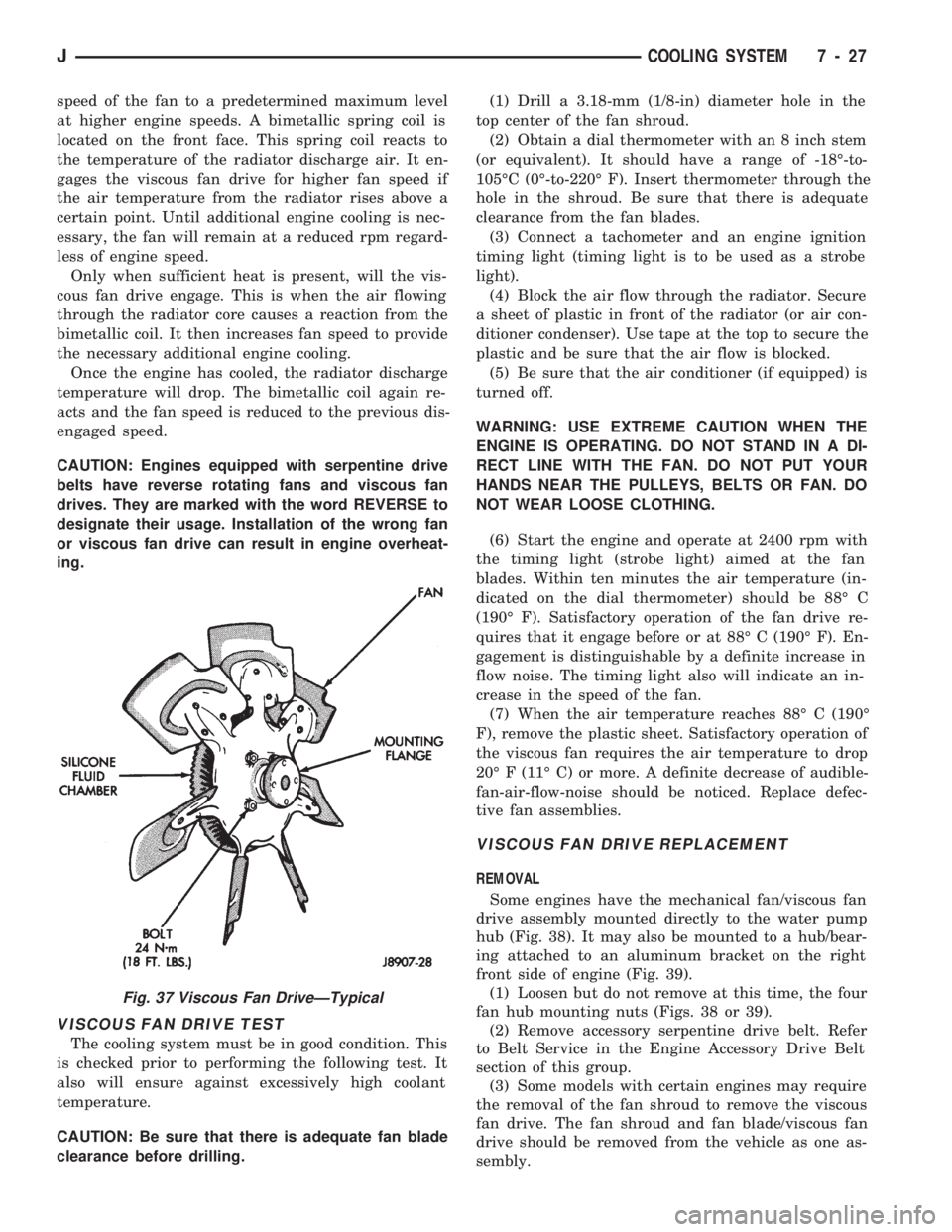
CAUTION: Engines equipped with serpentine drive
belts have reverse rotating fans and viscous fan
drives. They are marked with the word REVERSE to
designate their usage. Installation of the wrong fan
or viscous fan drive can result in engine overheat-
ing.
VISCOUS FAN DRIVE TEST
The cooling system must be in good condition. This
is checked prior to performing the following test. It
also will ensure against excessively high coolant
temperature.
CAUTION: Be sure that there is adequate fan blade
clearance before drilling.(1) Drill a 3.18-mm (1/8-in) diameter hole in the
top center of the fan shroud.
(2) Obtain a dial thermometer with an 8 inch stem
(or equivalent). It should have a range of -18É-to-
105ÉC (0É-to-220É F). Insert thermometer through the
hole in the shroud. Be sure that there is adequate
clearance from the fan blades.
(3) Connect a tachometer and an engine ignition
timing light (timing light is to be used as a strobe
light).
(4) Block the air flow through the radiator. Secure
a sheet of plastic in front of the radiator (or air con-
ditioner condenser). Use tape at the top to secure the
plastic and be sure that the air flow is blocked.
(5) Be sure that the air conditioner (if equipped) is
turned off.
WARNING: USE EXTREME CAUTION WHEN THE
ENGINE IS OPERATING. DO NOT STAND IN A DI-
RECT LINE WITH THE FAN. DO NOT PUT YOUR
HANDS NEAR THE PULLEYS, BELTS OR FAN. DO
NOT WEAR LOOSE CLOTHING.
(6) Start the engine and operate at 2400 rpm with
the timing light (strobe light) aimed at the fan
blades. Within ten minutes the air temperature (in-
dicated on the dial thermometer) should be 88É C
(190É F). Satisfactory operation of the fan drive re-
quires that it engage before or at 88É C (190É F). En-
gagement is distinguishable by a definite increase in
flow noise. The timing light also will indicate an in-
crease in the speed of the fan.
(7) When the air temperature reaches 88É C (190É
F), remove the plastic sheet. Satisfactory operation of
the viscous fan requires the air temperature to drop
20É F (11É C) or more. A definite decrease of audible-
fan-air-flow-noise should be noticed. Replace defec-
tive fan assemblies.
VISCOUS FAN DRIVE REPLACEMENT
REMOVAL
Some engines have the mechanical fan/viscous fan
drive assembly mounted directly to the water pump
hub (Fig. 38). It may also be mounted to a hub/bear-
ing attached to an aluminum bracket on the right
front side of engine (Fig. 39).
(1) Loosen but do not remove at this time, the four
fan hub mounting nuts (Figs. 38 or 39).
(2) Remove accessory serpentine drive belt. Refer
to Belt Service in the Engine Accessory Drive Belt
section of this group.
(3) Some models with certain engines may require
the removal of the fan shroud to remove the viscous
fan drive. The fan shroud and fan blade/viscous fan
drive should be removed from the vehicle as one as-
sembly.
Fig. 37 Viscous Fan DriveÐTypical
JCOOLING SYSTEM 7 - 27
Page 262 of 1784
through the relay. When coolant temperature is be-
low 88ÉC (190ÉF), the PCM opens the ground path to
the relay. This will prevent the cooling fan from be-
ing energized.
Whenever the air conditioning is used, the PCM
engages the auxiliary cooling fan. It provides a
ground path to the cooling fan relay.
DIAGNOSIS
The powertrain control module (PCM) will enter a
diagnostic trouble code (DTC) number 35 in memory
if it detects a problem in the auxiliary cooling fan re-
lay or circuit. This will be read as a flashing signal
at the instrument panel mounted Malfunction Indica-
tor Lamp (formerly referred to as the Check Engine
Lamp). Refer to On-Board Diagnostics in Group 14,
Fuel Systems for information on accessing a DTC.
The DTC can also be accessed through the DRB
scan tool. Refer to the appropriate Powertrain Diag-
nostic Procedures manual for diagnostic information
and operation of the DRB scan tool.
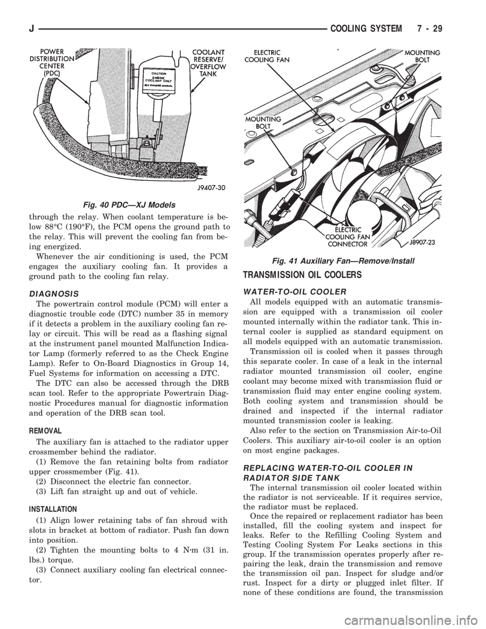
REMOVAL
The auxiliary fan is attached to the radiator upper
crossmember behind the radiator.
(1) Remove the fan retaining bolts from radiator
upper crossmember (Fig. 41).
(2) Disconnect the electric fan connector.
(3) Lift fan straight up and out of vehicle.
INSTALLATION
(1) Align lower retaining tabs of fan shroud with
slots in bracket at bottom of radiator. Push fan down
into position.
(2) Tighten the mounting bolts to 4 Nzm (31 in.
lbs.) torque.
(3) Connect auxiliary cooling fan electrical connec-
tor.
TRANSMISSION OIL COOLERS
WATER-TO-OIL COOLER
All models equipped with an automatic transmis-
sion are equipped with a transmission oil cooler
mounted internally within the radiator tank. This in-
ternal cooler is supplied as standard equipment on
all models equipped with an automatic transmission.
Transmission oil is cooled when it passes through
this separate cooler. In case of a leak in the internal
radiator mounted transmission oil cooler, engine
coolant may become mixed with transmission fluid or
transmission fluid may enter engine cooling system.
Both cooling system and transmission should be
drained and inspected if the internal radiator
mounted transmission cooler is leaking.
Also refer to the section on Transmission Air-to-Oil
Coolers. This auxiliary air-to-oil cooler is an option
on most engine packages.
REPLACING WATER-TO-OIL COOLER IN
RADIATOR SIDE TANK
The internal transmission oil cooler located within
the radiator is not serviceable. If it requires service,
the radiator must be replaced.
Once the repaired or replacement radiator has been
installed, fill the cooling system and inspect for
leaks. Refer to the Refilling Cooling System and
Testing Cooling System For Leaks sections in this
group. If the transmission operates properly after re-
pairing the leak, drain the transmission and remove
the transmission oil pan. Inspect for sludge and/or
rust. Inspect for a dirty or plugged inlet filter. If
none of these conditions are found, the transmission
Fig. 40 PDCÐXJ Models
Fig. 41 Auxiliary FanÐRemove/Install
JCOOLING SYSTEM 7 - 29