1994 JEEP CHEROKEE automatic transmission
[x] Cancel search: automatic transmissionPage 122 of 1784
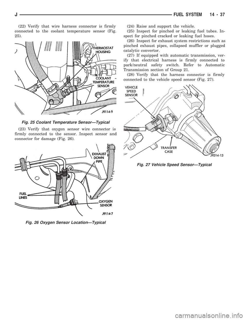
(22) Verify that wire harness connector is firmly
connected to the coolant temperature sensor (Fig.
25).
(23) Verify that oxygen sensor wire connector is
firmly connected to the sensor. Inspect sensor and
connector for damage (Fig. 26).(24) Raise and support the vehicle.
(25) Inspect for pinched or leaking fuel tubes. In-
spect for pinched cracked or leaking fuel hoses.
(26) Inspect for exhaust system restrictions such as
pinched exhaust pipes, collapsed muffler or plugged
catalytic convertor.
(27) If equipped with automatic transmission, ver-
ify that electrical harness is firmly connected to
park/neutral safety switch. Refer to Automatic
Transmission section of Group 21.
(28) Verify that the harness connector is firmly
connected to the vehicle speed sensor (Fig. 27).
Fig. 25 Coolant Temperature SensorÐTypical
Fig. 26 Oxygen Sensor LocationÐTypical
Fig. 27 Vehicle Speed SensorÐTypical
JFUEL SYSTEM 14 - 37
Page 123 of 1784
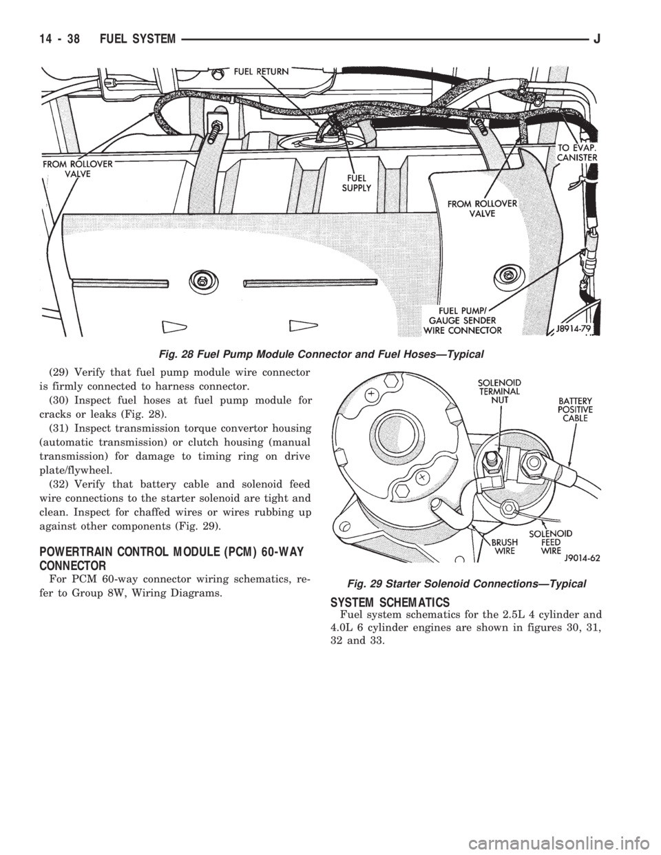
(29) Verify that fuel pump module wire connector
is firmly connected to harness connector.
(30) Inspect fuel hoses at fuel pump module for
cracks or leaks (Fig. 28).
(31) Inspect transmission torque convertor housing
(automatic transmission) or clutch housing (manual
transmission) for damage to timing ring on drive
plate/flywheel.
(32) Verify that battery cable and solenoid feed
wire connections to the starter solenoid are tight and
clean. Inspect for chaffed wires or wires rubbing up
against other components (Fig. 29).
POWERTRAIN CONTROL MODULE (PCM) 60-WAY
CONNECTOR
For PCM 60-way connector wiring schematics, re-
fer to Group 8W, Wiring Diagrams.
SYSTEM SCHEMATICS
Fuel system schematics for the 2.5L 4 cylinder and
4.0L 6 cylinder engines are shown in figures 30, 31,
32 and 33.
Fig. 28 Fuel Pump Module Connector and Fuel HosesÐTypical
Fig. 29 Starter Solenoid ConnectionsÐTypical
14 - 38 FUEL SYSTEMJ
Page 141 of 1784
INSTALLATION
(1) Install the fuel injector(s) into the fuel rail as-
sembly and install retaining clip(s).
(2) Install fuel rail. Refer to Fuel Rail Installation
in this section.
(3) Start engine and check for fuel leaks.
FUEL PUMP MODULE
Refer to the Fuel Delivery System section of this
group for removal/installation procedures.
FUEL PUMP RELAY
The Fuel Pump relay is located in the Power Dis-
tribution Center (PDC) (Figs. 1 or 2). For location of
this relay within the PDC, refer to label on PDC
cover.
FUEL RAIL ASSEMBLY
REMOVAL
WARNING: THE FUEL SYSTEM IS UNDER CON-
STANT FUEL PRESSURE (EVEN WITH THE ENGINE
OFF) OF APPROXIMATELY 131-269 KPA (19-39
PSI). THIS PRESSURE MUST BE RELEASED BE-
FORE SERVICING THE FUEL RAIL.
(1) Remove fuel tank filler tube cap.
(2) Disconnect the negative battery cable from bat-
tery.
(3) Perform the Fuel System Pressure Release Pro-
cedure as described in the Fuel Delivery System sec-
tion of this Group.
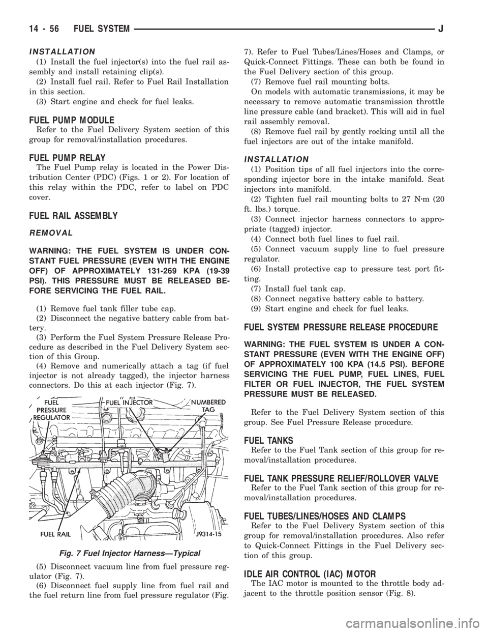
(4) Remove and numerically attach a tag (if fuel
injector is not already tagged), the injector harness
connectors. Do this at each injector (Fig. 7).
(5) Disconnect vacuum line from fuel pressure reg-
ulator (Fig. 7).
(6) Disconnect fuel supply line from fuel rail and
the fuel return line from fuel pressure regulator (Fig.7). Refer to Fuel Tubes/Lines/Hoses and Clamps, or
Quick-Connect Fittings. These can both be found in
the Fuel Delivery section of this group.
(7) Remove fuel rail mounting bolts.
On models with automatic transmissions, it may be
necessary to remove automatic transmission throttle
line pressure cable (and bracket). This will aid in fuel
rail assembly removal.
(8) Remove fuel rail by gently rocking until all the
fuel injectors are out of the intake manifold.
INSTALLATION
(1) Position tips of all fuel injectors into the corre-
sponding injector bore in the intake manifold. Seat
injectors into manifold.
(2) Tighten fuel rail mounting bolts to 27 Nzm (20
ft. lbs.) torque.
(3) Connect injector harness connectors to appro-
priate (tagged) injector.
(4) Connect both fuel lines to fuel rail.
(5) Connect vacuum supply line to fuel pressure
regulator.
(6) Install protective cap to pressure test port fit-
ting.
(7) Install fuel tank cap.
(8) Connect negative battery cable to battery.
(9) Start engine and check for fuel leaks.
FUEL SYSTEM PRESSURE RELEASE PROCEDURE
WARNING: THE FUEL SYSTEM IS UNDER A CON-
STANT PRESSURE (EVEN WITH THE ENGINE OFF)
OF APPROXIMATELY 100 KPA (14.5 PSI). BEFORE
SERVICING THE FUEL PUMP, FUEL LINES, FUEL
FILTER OR FUEL INJECTOR, THE FUEL SYSTEM
PRESSURE MUST BE RELEASED.
Refer to the Fuel Delivery System section of this
group. See Fuel Pressure Release procedure.
FUEL TANKS
Refer to the Fuel Tank section of this group for re-
moval/installation procedures.
FUEL TANK PRESSURE RELIEF/ROLLOVER VALVE
Refer to the Fuel Tank section of this group for re-
moval/installation procedures.
FUEL TUBES/LINES/HOSES AND CLAMPS
Refer to the Fuel Delivery System section of this
group for removal/installation procedures. Also refer
to Quick-Connect Fittings in the Fuel Delivery sec-
tion of this group.
IDLE AIR CONTROL (IAC) MOTOR
The IAC motor is mounted to the throttle body ad-
jacent to the throttle position sensor (Fig. 8).
Fig. 7 Fuel Injector HarnessÐTypical
14 - 56 FUEL SYSTEMJ
Page 144 of 1784
INSTALLATION
(1) After the PCM electrical connector has been
separated from the PCM, inspect the pins for corro-
sion, being spread apart, bent or misaligned. Also in-
spect the pin heights in the connector. If the pin
heights are different, this would indicate a pin has
separated from the connector. Repair as necessary.
(2) Install PCM. Tighten three mounting bolts to 1
Nzm (9 in. lbs.) torque.
(3) Engage 60-way connector into PCM. Tighten
connector mounting bolt to 4 Nzm (35 in. lbs.) torque.
(4) YJ Models: Install windshield washer fluid
tank.
(5) Connect negative cable to battery.
QUICK-CONNECT FITTINGS
Refer to the Fuel Delivery System section of this
group for removal/installation procedures.
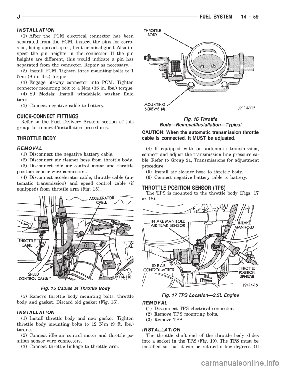
THROTTLE BODY
REMOVAL
(1) Disconnect the negative battery cable.
(2) Disconnect air cleaner hose from throttle body.
(3) Disconnect idle air control motor and throttle
position sensor wire connectors.
(4) Disconnect accelerator cable, throttle cable (au-
tomatic transmission) and speed control cable (if
equipped) from throttle arm (Fig. 15).
(5) Remove throttle body mounting bolts, throttle
body and gasket. Discard old gasket (Fig. 16).
INSTALLATION
(1) Install throttle body and new gasket. Tighten
throttle body mounting bolts to 12 Nzm (9 ft. lbs.)
torque.
(2) Connect idle air control motor and throttle po-
sition sensor wire connectors.
(3) Connect throttle linkage to throttle arm.CAUTION: When the automatic transmission throttle
cable is connected, it MUST be adjusted.
(4) If equipped with an automatic transmission,
connect and adjust the transmission line pressure ca-
ble. Refer to Group 21, Transmissions for adjustment
procedure.
(5) Install air cleaner hose to throttle body.
(6) Connect negative battery cable to battery.
THROTTLE POSITION SENSOR (TPS)
The TPS is mounted to the throttle body (Figs. 17
or 18).
REMOVAL
(1) Disconnect TPS electrical connector.
(2) Remove TPS mounting bolts.
(3) Remove TPS.
INSTALLATION
The throttle shaft end of the throttle body slides
into a socket in the TPS (Fig. 19). The TPS must be
installed so that it can be rotated a few degrees. (If
Fig. 16 Throttle
BodyÐRemoval/InstallationÐTypical
Fig. 17 TPS LocationÐ2.5L Engine
Fig. 15 Cables at Throttle Body
JFUEL SYSTEM 14 - 59
Page 206 of 1784
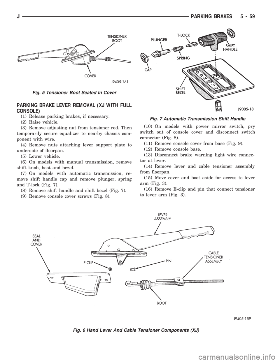
PARKING BRAKE LEVER REMOVAL (XJ WITH FULL
CONSOLE)
(1) Release parking brakes, if necessary.
(2) Raise vehicle.
(3) Remove adjusting nut from tensioner rod. Then
temporarily secure equalizer to nearby chassis com-
ponent with wire.
(4) Remove nuts attaching lever support plate to
underside of floorpan.
(5) Lower vehicle.
(6) On models with manual transmission, remove
shift knob, boot and bezel.
(7) On models with automatic transmission, re-
move shift handle cap and remove plunger, spring
and T-lock (Fig. 7).
(8) Remove shift handle and shift bezel (Fig. 7).
(9) Remove console cover screws (Fig. 8).(10) On models with power mirror switch, pry
switch out of console cover and disconnect switch
connector (Fig. 8).
(11) Remove console cover from base (Fig. 9).
(12) Remove console base.
(13) Disconnect brake warning light wire connec-
tor at lever.
(14) Remove lever and cable tensioner assembly
from floorpan.
(15) Move cover and boot aside for access to lever
arm (Fig. 3).
(16) Remove E-clip and pin that connect tensioner
to lever arm (Fig. 3).
Fig. 6 Hand Lever And Cable Tensioner Components (XJ)
Fig. 5 Tensioner Boot Seated In Cover
Fig. 7 Automatic Transmission Shift Handle
JPARKING BRAKES 5 - 59
Page 207 of 1784
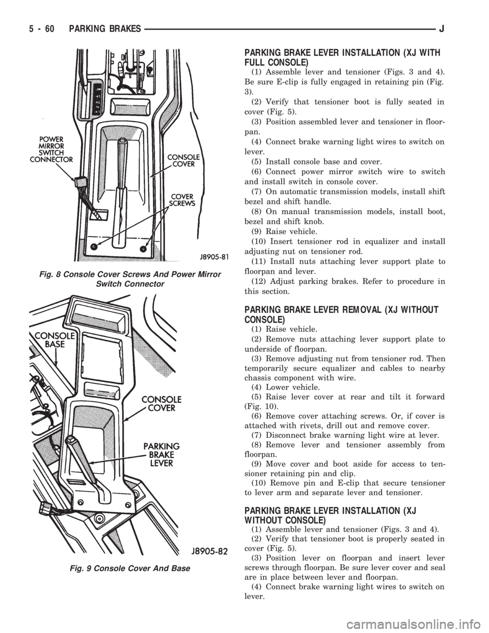
PARKING BRAKE LEVER INSTALLATION (XJ WITH
FULL CONSOLE)
(1) Assemble lever and tensioner (Figs. 3 and 4).
Be sure E-clip is fully engaged in retaining pin (Fig.
3).
(2) Verify that tensioner boot is fully seated in
cover (Fig. 5).
(3) Position assembled lever and tensioner in floor-
pan.
(4) Connect brake warning light wires to switch on
lever.
(5) Install console base and cover.
(6) Connect power mirror switch wire to switch
and install switch in console cover.
(7) On automatic transmission models, install shift
bezel and shift handle.
(8) On manual transmission models, install boot,
bezel and shift knob.
(9) Raise vehicle.
(10) Insert tensioner rod in equalizer and install
adjusting nut on tensioner rod.
(11) Install nuts attaching lever support plate to
floorpan and lever.
(12) Adjust parking brakes. Refer to procedure in
this section.
PARKING BRAKE LEVER REMOVAL (XJ WITHOUT
CONSOLE)
(1) Raise vehicle.
(2) Remove nuts attaching lever support plate to
underside of floorpan.
(3) Remove adjusting nut from tensioner rod. Then
temporarily secure equalizer and cables to nearby
chassis component with wire.
(4) Lower vehicle.
(5) Raise lever cover at rear and tilt it forward
(Fig. 10).
(6) Remove cover attaching screws. Or, if cover is
attached with rivets, drill out and remove cover.
(7) Disconnect brake warning light wire at lever.
(8) Remove lever and tensioner assembly from
floorpan.
(9) Move cover and boot aside for access to ten-
sioner retaining pin and clip.
(10) Remove pin and E-clip that secure tensioner
to lever arm and separate lever and tensioner.
PARKING BRAKE LEVER INSTALLATION (XJ
WITHOUT CONSOLE)
(1) Assemble lever and tensioner (Figs. 3 and 4).
(2) Verify that tensioner boot is properly seated in
cover (Fig. 5).
(3) Position lever on floorpan and insert lever
screws through floorpan. Be sure lever cover and seal
are in place between lever and floorpan.
(4) Connect brake warning light wires to switch on
lever.
Fig. 8 Console Cover Screws And Power Mirror
Switch Connector
Fig. 9 Console Cover And Base
5 - 60 PARKING BRAKESJ
Page 213 of 1784
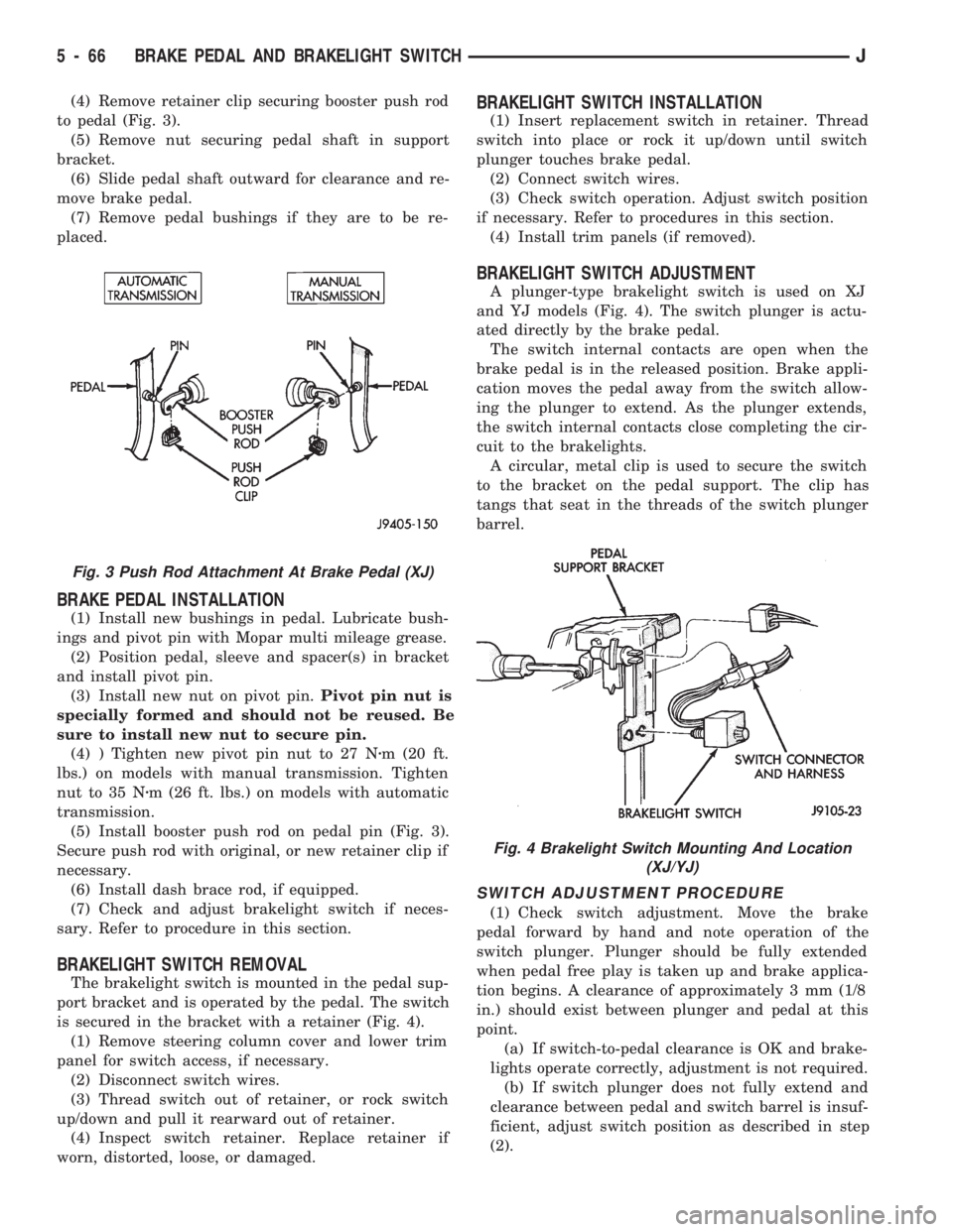
(4) Remove retainer clip securing booster push rod
to pedal (Fig. 3).
(5) Remove nut securing pedal shaft in support
bracket.
(6) Slide pedal shaft outward for clearance and re-
move brake pedal.
(7) Remove pedal bushings if they are to be re-
placed.
BRAKE PEDAL INSTALLATION
(1) Install new bushings in pedal. Lubricate bush-
ings and pivot pin with Mopar multi mileage grease.
(2) Position pedal, sleeve and spacer(s) in bracket
and install pivot pin.
(3) Install new nut on pivot pin.Pivot pin nut is
specially formed and should not be reused. Be
sure to install new nut to secure pin.
(4) ) Tighten new pivot pin nut to 27 Nzm (20 ft.
lbs.) on models with manual transmission. Tighten
nut to 35 Nzm (26 ft. lbs.) on models with automatic
transmission.
(5) Install booster push rod on pedal pin (Fig. 3).
Secure push rod with original, or new retainer clip if
necessary.
(6) Install dash brace rod, if equipped.
(7) Check and adjust brakelight switch if neces-
sary. Refer to procedure in this section.
BRAKELIGHT SWITCH REMOVAL
The brakelight switch is mounted in the pedal sup-
port bracket and is operated by the pedal. The switch
is secured in the bracket with a retainer (Fig. 4).
(1) Remove steering column cover and lower trim
panel for switch access, if necessary.
(2) Disconnect switch wires.
(3) Thread switch out of retainer, or rock switch
up/down and pull it rearward out of retainer.
(4) Inspect switch retainer. Replace retainer if
worn, distorted, loose, or damaged.
BRAKELIGHT SWITCH INSTALLATION
(1) Insert replacement switch in retainer. Thread
switch into place or rock it up/down until switch
plunger touches brake pedal.
(2) Connect switch wires.
(3) Check switch operation. Adjust switch position
if necessary. Refer to procedures in this section.
(4) Install trim panels (if removed).
BRAKELIGHT SWITCH ADJUSTMENT
A plunger-type brakelight switch is used on XJ
and YJ models (Fig. 4). The switch plunger is actu-
ated directly by the brake pedal.
The switch internal contacts are open when the
brake pedal is in the released position. Brake appli-
cation moves the pedal away from the switch allow-
ing the plunger to extend. As the plunger extends,
the switch internal contacts close completing the cir-
cuit to the brakelights.
A circular, metal clip is used to secure the switch
to the bracket on the pedal support. The clip has
tangs that seat in the threads of the switch plunger
barrel.
SWITCH ADJUSTMENT PROCEDURE
(1) Check switch adjustment. Move the brake
pedal forward by hand and note operation of the
switch plunger. Plunger should be fully extended
when pedal free play is taken up and brake applica-
tion begins. A clearance of approximately 3 mm (1/8
in.) should exist between plunger and pedal at this
point.
(a) If switch-to-pedal clearance is OK and brake-
lights operate correctly, adjustment is not required.
(b) If switch plunger does not fully extend and
clearance between pedal and switch barrel is insuf-
ficient, adjust switch position as described in step
(2).
Fig. 3 Push Rod Attachment At Brake Pedal (XJ)
Fig. 4 Brakelight Switch Mounting And Location
(XJ/YJ)
5 - 66 BRAKE PEDAL AND BRAKELIGHT SWITCHJ
Page 248 of 1784
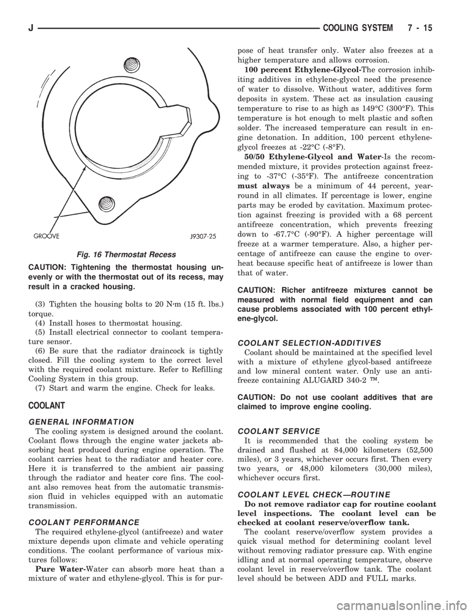
CAUTION: Tightening the thermostat housing un-
evenly or with the thermostat out of its recess, may
result in a cracked housing.
(3) Tighten the housing bolts to 20 Nzm (15 ft. lbs.)
torque.
(4) Install hoses to thermostat housing.
(5) Install electrical connector to coolant tempera-
ture sensor.
(6) Be sure that the radiator draincock is tightly
closed. Fill the cooling system to the correct level
with the required coolant mixture. Refer to Refilling
Cooling System in this group.
(7) Start and warm the engine. Check for leaks.
COOLANT
GENERAL INFORMATION
The cooling system is designed around the coolant.
Coolant flows through the engine water jackets ab-
sorbing heat produced during engine operation. The
coolant carries heat to the radiator and heater core.
Here it is transferred to the ambient air passing
through the radiator and heater core fins. The cool-
ant also removes heat from the automatic transmis-
sion fluid in vehicles equipped with an automatic
transmission.
COOLANT PERFORMANCE
The required ethylene-glycol (antifreeze) and water
mixture depends upon climate and vehicle operating
conditions. The coolant performance of various mix-
tures follows:
Pure Water-Water can absorb more heat than a
mixture of water and ethylene-glycol. This is for pur-pose of heat transfer only. Water also freezes at a
higher temperature and allows corrosion.
100 percent Ethylene-Glycol-The corrosion inhib-
iting additives in ethylene-glycol need the presence
of water to dissolve. Without water, additives form
deposits in system. These act as insulation causing
temperature to rise to as high as 149ÉC (300ÉF). This
temperature is hot enough to melt plastic and soften
solder. The increased temperature can result in en-
gine detonation. In addition, 100 percent ethylene-
glycol freezes at -22ÉC (-8ÉF).
50/50 Ethylene-Glycol and Water-Is the recom-
mended mixture, it provides protection against freez-
ing to -37ÉC (-35ÉF). The antifreeze concentration
must alwaysbe a minimum of 44 percent, year-
round in all climates. If percentage is lower, engine
parts may be eroded by cavitation. Maximum protec-
tion against freezing is provided with a 68 percent
antifreeze concentration, which prevents freezing
down to -67.7ÉC (-90ÉF). A higher percentage will
freeze at a warmer temperature. Also, a higher per-
centage of antifreeze can cause the engine to over-
heat because specific heat of antifreeze is lower than
that of water.
CAUTION: Richer antifreeze mixtures cannot be
measured with normal field equipment and can
cause problems associated with 100 percent ethyl-
ene-glycol.
COOLANT SELECTION-ADDITIVES
Coolant should be maintained at the specified level
with a mixture of ethylene glycol-based antifreeze
and low mineral content water. Only use an anti-
freeze containing ALUGARD 340-2 Ÿ.
CAUTION: Do not use coolant additives that are
claimed to improve engine cooling.
COOLANT SERVICE
It is recommended that the cooling system be
drained and flushed at 84,000 kilometers (52,500
miles), or 3 years, whichever occurs first. Then every
two years, or 48,000 kilometers (30,000 miles),
whichever occurs first.
COOLANT LEVEL CHECKÐROUTINE
Do not remove radiator cap for routine coolant
level inspections. The coolant level can be
checked at coolant reserve/overflow tank.
The coolant reserve/overflow system provides a
quick visual method for determining coolant level
without removing radiator pressure cap. With engine
idling and at normal operating temperature, observe
coolant level in reserve/overflow tank. The coolant
level should be between ADD and FULL marks.
Fig. 16 Thermostat Recess
JCOOLING SYSTEM 7 - 15