1994 JEEP CHEROKEE sensor
[x] Cancel search: sensorPage 1115 of 1784
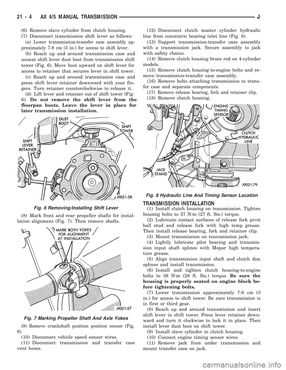
(6) Remove slave cylinder from clutch housing.
(7) Disconnect transmission shift lever as follows:
(a) Lower transmission-transfer case assembly ap-
proximately 7-8 cm (3 in.) for access to shift lever.
(b) Reach up and around transmission case and
unseat shift lever dust boot from transmission shift
tower (Fig. 6). Move boot upward on shift lever for
access to retainer that secures lever in shift tower.
(c) Reach up and around transmission case and
press shift lever retainer downward with your fin-
gers. Turn retainer counterclockwise to release it.
(d) Lift lever and retainer out of shift tower (Fig.
6).Do not remove the shift lever from the
floorpan boots. Leave the lever in place for
later transmission installation.
(8) Mark front and rear propeller shafts for instal-
lation alignment (Fig. 7). Then remove shafts.
(9) Remove crankshaft position position sensor (Fig.
8).
(10) Disconnect vehicle speed sensor wires.
(11) Disconnect transmission and transfer case
vent hoses.(12) Disconnect clutch master cylinder hydraulic
line from concentric bearing inlet line (Fig. 8).
(13) Support transmission-transfer case assembly
with a transmission jack. Secure assembly to jack
with safety chains.
(14) Remove clutch housing brace rod on 4-cylinder
models.
(15) Remove clutch housing-to-engine bolts and re-
move transmission-transfer case assembly.
(16) Remove bolts attaching transmission to trans-
fer case and separate components.
(17) Remove release bearing, fork and retainer clip.
(18) Remove clutch housing.
TRANSMISSION INSTALLATION
(1) Install clutch housing on transmission. Tighten
housing bolts to 37 Nzm (27 ft. lbs.) torque.
(2) Lubricate contact surfaces of release fork pivot
ball stud and release fork with high temp grease.
Then install release bearing, fork and retainer clip.
(3) Mount transmission on transmission jack.
(4) Lightly lubricate pilot bearing and transmis-
sion input shaft splines with Mopar high tempera-
ture grease.
(5) Align transmission input shaft and clutch disc
splines and install transmission.
(6) Install and tighten clutch housing-to-engine
bolts to 38 Nzm (28 ft. lbs.) torque.Be sure the
housing is properly seated on engine block be-
fore tightening bolts.
(7) Lower transmission approximately 7-8 cm (3
in.) for access to shift tower. Be sure transmission is
in first or third gear.
(8) Reach up and around transmission and insert
shift lever in shift tower. Press lever retainer down-
ward and turn it clockwise to lock it in place. Then
install lever dust boot on shift tower.
(9) Install slave cylinder in clutch housing.
(10) Connect engine timing sensor wires.
(11) Remove jack from under transmission and
mount transfer case on jack.Fig. 6 Removing/Installing Shift Lever
Fig. 7 Marking Propeller Shaft And Axle Yokes
Fig. 8 Hydraulic Line And Timing Sensor Location
21 - 4 AX 4/5 MANUAL TRANSMISSIONJ
Page 1116 of 1784
(12) Align transfer case and transmission shafts
and install transfer case. Tighten transfer case-to-
transmission nuts/bolts to 35 Nzm (26 ft. lbs.) torque.
(13) Remove jack stand from under engine and re-
position jack under transmission. Then remove trans-
mission jack.
(14) Connect transfer case vent hose and shift link-
age. Check and adjust linkage if necessary.
(15) Connect transmission and transfer case vent
hoses.
(16) Connect backup light switch wires.
(17) Connect vehicle speed sensor wires.
(18) Install and connect crankshaft position sensor
if equipped.
(19) Install rear crossmember, or skid plate (Fig. 5).
On XJ, tighten crossmember-to-frame bolts to 41 Nzm
(31 ft. lbs.) torque. Then tighten transmission-to-rear
support bolts/nuts to 45 Nzm (33 ft. lbs.) torque. On YJ,
tighten bolts/nuts to indicated torque (Fig. 5).
(20) Align and install front/rear propeller shafts.
Tighten shaft U-joint clamp bolts to 19 Nzm (170 in.
lbs.) torque.
(21) On XJ, install skid plate, if removed. Tighten
bolts to 42 Nzm (31 ft. lbs.) torque. Tighten stud nuts
to 17 Nzm (150 in. lbs.) torque.
(22) Top off transmission and transfer case lubri-
cant levels.
(23) Lower vehicle.
TRANSMISSION DISASSEMBLY AND OVERHAUL
ADAPTER HOUSING AND FRONT BEARING
RETAINER REMOVAL
(1) Drain transmission lubricant.
(2) Remove concentric bearing.
(3) Remove clutch housing bolts and remove housing.
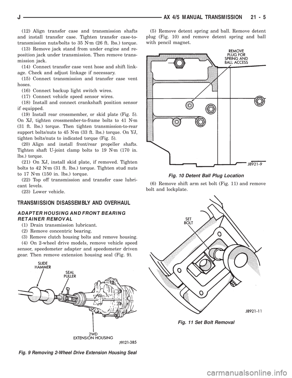
(4) On 2-wheel drive models, remove vehicle speed
sensor, speedometer adapter and speedometer driven
gear. Then remove extension housing seal (Fig. 9).(5) Remove detent spring and ball. Remove detent
plug (Fig. 10) and remove detent spring and ball
with pencil magnet.
(6) Remove shift arm set bolt (Fig. 11) and remove
bolt and lockplate.
Fig. 10 Detent Ball Plug Location
Fig. 11 Set Bolt Removal
Fig. 9 Removing 2-Wheel Drive Extension Housing Seal
JAX 4/5 MANUAL TRANSMISSION 21 - 5
Page 1142 of 1784
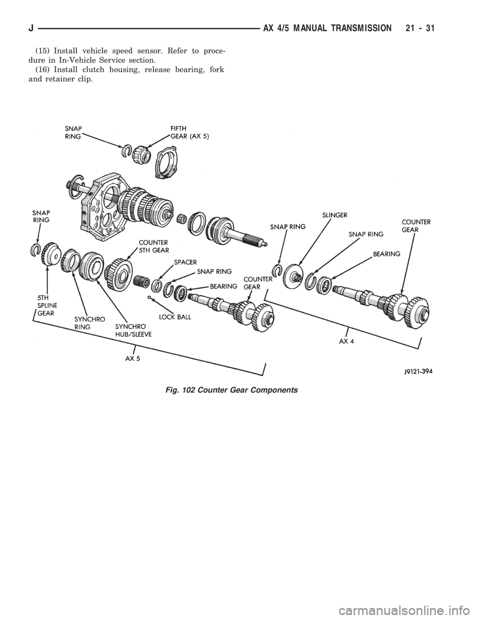
(15) Install vehicle speed sensor. Refer to proce-
dure in In-Vehicle Service section.
(16) Install clutch housing, release bearing, fork
and retainer clip.
Fig. 102 Counter Gear Components
JAX 4/5 MANUAL TRANSMISSION 21 - 31
Page 1146 of 1784
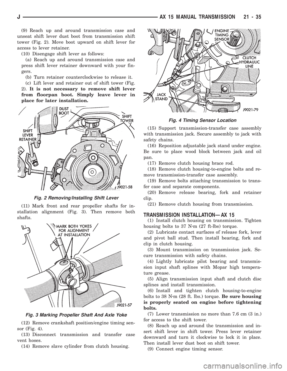
(9) Reach up and around transmission case and
unseat shift lever dust boot from transmission shift
tower (Fig. 2). Move boot upward on shift lever for
access to lever retainer.
(10) Disengage shift lever as follows:
(a) Reach up and around transmission case and
press shift lever retainer downward with your fin-
gers.
(b) Turn retainer counterclockwise to release it.
(c) Lift lever and retainer out of shift tower (Fig.
2).It is not necessary to remove shift lever
from floorpan boot. Simply leave lever in
place for later installation.
(11) Mark front and rear propeller shafts for in-
stallation alignment (Fig. 3). Then remove both
shafts.
(12) Remove crankshaft position/engine timing sen-
sor (Fig. 4).
(13) Disconnect transmission and transfer case
vent hoses.
(14) Remove slave cylinder from clutch housing.(15) Support transmission-transfer case assembly
with transmission jack. Secure assembly to jack with
safety chains.
(16) Reposition adjustable jack stand under engine.
Be sure to place wood block between jack and oil
pan.
(17) Remove clutch housing brace rod.
(18) Remove clutch housing-to-engine bolts and re-
move transmission-transfer case assembly.
(19) Remove bolts attaching transmission to trans-
fer case and separate components.
(20) Remove release bearing, fork and retainer
clip.
(21) Remove clutch housing from transmission.
TRANSMISSION INSTALLATIONÐAX 15
(1) Install clutch housing on transmission. Tighten
housing bolts to 37 Nzm (27 ft-lbs) torque.
(2) Lubricate contact surfaces of release fork, lever
and pivot ball stud. Then install bearing, fork and
clip in clutch housing.
(3) Mount transmission on transmission jack. Se-
cure transmission with safety chains.
(4) Lightly lubricate pilot bearing and transmis-
sion input shaft splines with Mopar high tempera-
ture grease.
(5) Align transmission input shaft and clutch disc
splines and install transmission.
(6) Install and tighten clutch housing-to-engine
bolts to 38 Nzm (28 ft. lbs.) torque.Be sure housing
is properly seated on engine before tightening
bolts.
(7) Lower transmission no more than 7.6 cm (3 in.)
for access to the shift tower.
(8) Reach up and around the transmission and in-
sert shift lever in shift tower. Press lever retainer
downward and turn it clockwise to lock it in place.
Then install lever dust boot on shift tower.
(9) Connect engine timing sensor.
Fig. 2 Removing/Installing Shift Lever
Fig. 3 Marking Propeller Shaft And Axle Yoke
Fig. 4 Timing Sensor Location
JAX 15 MANUAL TRANSMISSION 21 - 35
Page 1147 of 1784
(10) Remove jack from under transmission and
mount transfer case on jack.
(11) Align transfer case and transmission shafts
and install transfer case. Tighten transfer case-to-
transmission nuts/bolts to 35 Nzm (26 ft. lbs.) torque.
(12) Move jack stand from under engine and repo-
sition it under transmission. Then remove transmis-
sion jack.
(13) Connect transfer case vacuum hoses and link-
age. Check and adjust linkage if necessary.
(14) Connect transmission and transfer case vent
hoses and backup light switch wires.
(15) Install clutch sleeve cylinder.
(16) Connect vehicle speed sensor and wires.
(17) On XJ, install rear crossmember and attach
cushion and bracket. Tighten crossmember-to-frame
bolts to 41 Nzm (30 ft. lbs.) torque. Tighten transmis-
sion-to-rear cushion and bracket bolts/nuts to 45 Nzm
(33 ft. lbs.) torque.
(18) On YJ, install rear cushion and bracket and
skid plate. Tighten attaching bolts/nuts to indicated
torque (Fig. 1).
(19) Align and install front/rear propeller shafts.
Tighten shaft U-joint clamp bolts to 19 Nzm (170 in.
lbs.) torque.
(20) On XJ, install skid plate if removed. Tighten
bolts to 42 Nzm (31 ft. lbs.) torque. Tighten stud nuts
to 17 Nzm (150 in. lbs.) torque.
(21) Top off transmission and transfer lubricant
levels.
(22) Remove supports and lower vehicle.
TRANSMISSION DISASSEMBLY AND OVERHAUL
ADAPTER/EXTENSION HOUSING REMOVAL
(1) Remove release bearing, fork, retainer clip and
clutch housing from transmission. Also remove shift
lever if not previously removed.
(2) On 2-wheel drive models, remove extension
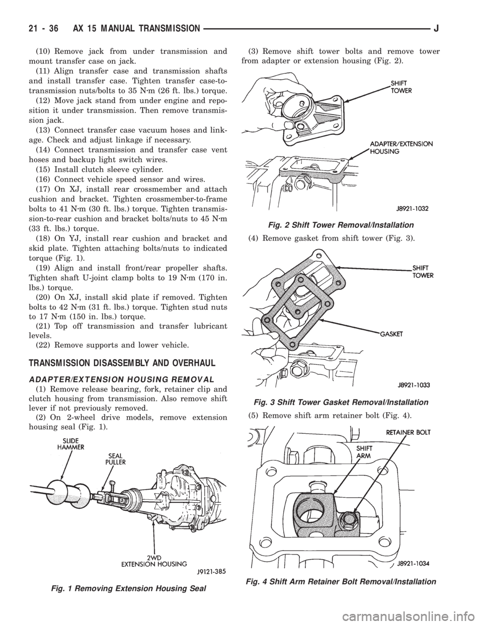
housing seal (Fig. 1).(3) Remove shift tower bolts and remove tower
from adapter or extension housing (Fig. 2).
(4) Remove gasket from shift tower (Fig. 3).
(5) Remove shift arm retainer bolt (Fig. 4).
Fig. 1 Removing Extension Housing Seal
Fig. 2 Shift Tower Removal/Installation
Fig. 3 Shift Tower Gasket Removal/Installation
Fig. 4 Shift Arm Retainer Bolt Removal/Installation
21 - 36 AX 15 MANUAL TRANSMISSIONJ
Page 1149 of 1784
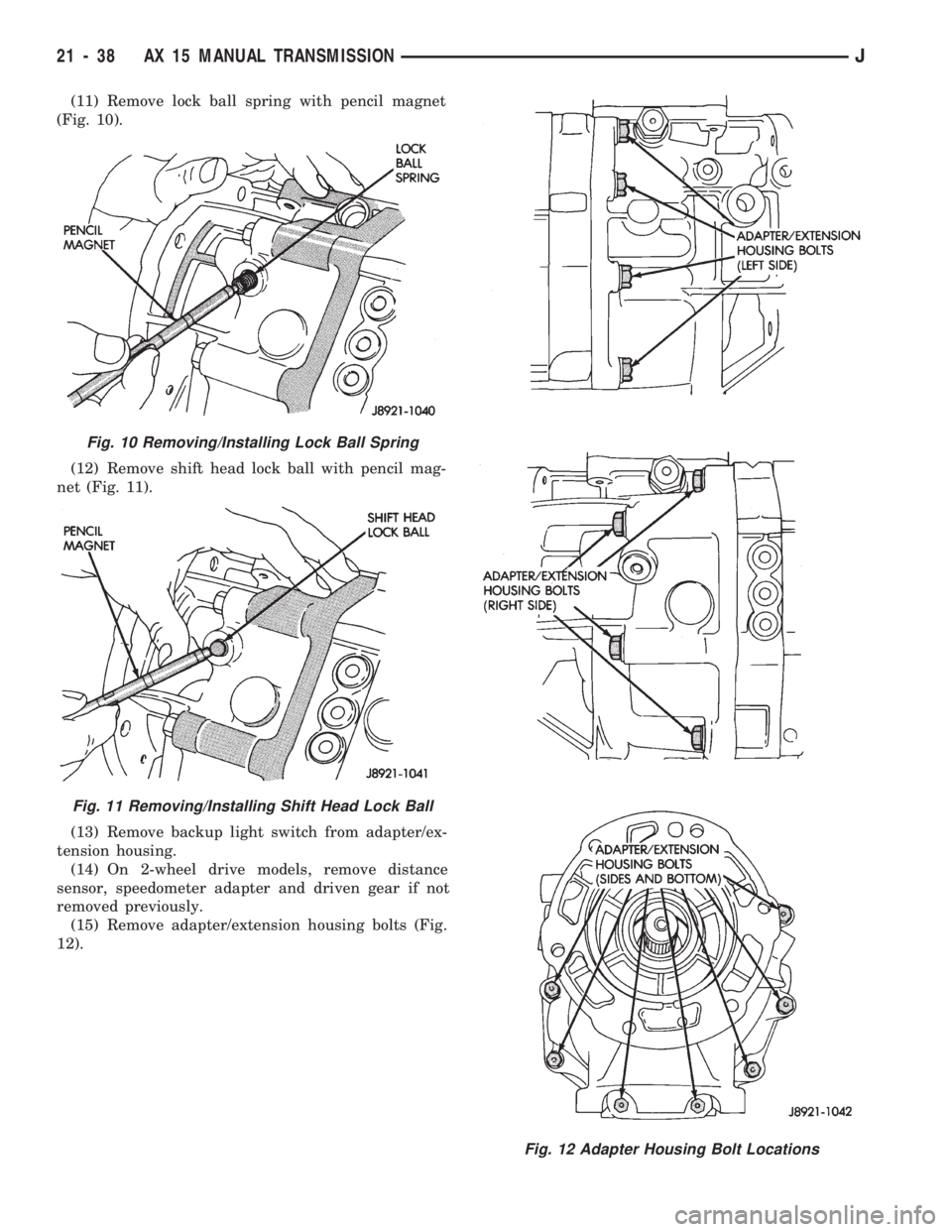
(11) Remove lock ball spring with pencil magnet
(Fig. 10).
(12) Remove shift head lock ball with pencil mag-
net (Fig. 11).
(13) Remove backup light switch from adapter/ex-
tension housing.
(14) On 2-wheel drive models, remove distance
sensor, speedometer adapter and driven gear if not
removed previously.
(15) Remove adapter/extension housing bolts (Fig.
12).
Fig. 10 Removing/Installing Lock Ball Spring
Fig. 11 Removing/Installing Shift Head Lock Ball
Fig. 12 Adapter Housing Bolt Locations
21 - 38 AX 15 MANUAL TRANSMISSIONJ
Page 1176 of 1784
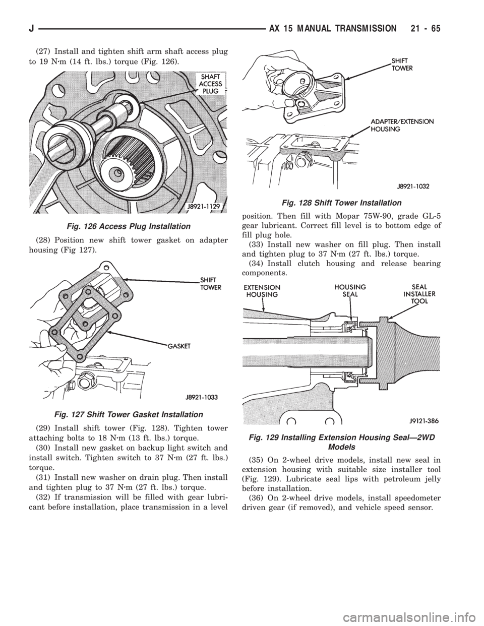
(27) Install and tighten shift arm shaft access plug
to 19 Nzm (14 ft. lbs.) torque (Fig. 126).
(28) Position new shift tower gasket on adapter
housing (Fig 127).
(29) Install shift tower (Fig. 128). Tighten tower
attaching bolts to 18 Nzm (13 ft. lbs.) torque.
(30) Install new gasket on backup light switch and
install switch. Tighten switch to 37 Nzm (27 ft. lbs.)
torque.
(31) Install new washer on drain plug. Then install
and tighten plug to 37 Nzm (27 ft. lbs.) torque.
(32) If transmission will be filled with gear lubri-
cant before installation, place transmission in a levelposition. Then fill with Mopar 75W-90, grade GL-5
gear lubricant. Correct fill level is to bottom edge of
fill plug hole.
(33) Install new washer on fill plug. Then install
and tighten plug to 37 Nzm (27 ft. lbs.) torque.
(34) Install clutch housing and release bearing
components.
(35) On 2-wheel drive models, install new seal in
extension housing with suitable size installer tool
(Fig. 129). Lubricate seal lips with petroleum jelly
before installation.
(36) On 2-wheel drive models, install speedometer
driven gear (if removed), and vehicle speed sensor.
Fig. 126 Access Plug Installation
Fig. 127 Shift Tower Gasket Installation
Fig. 128 Shift Tower Installation
Fig. 129 Installing Extension Housing SealÐ2WD
Models
JAX 15 MANUAL TRANSMISSION 21 - 65
Page 1213 of 1784
GOVERNOR DISASSEMBLY
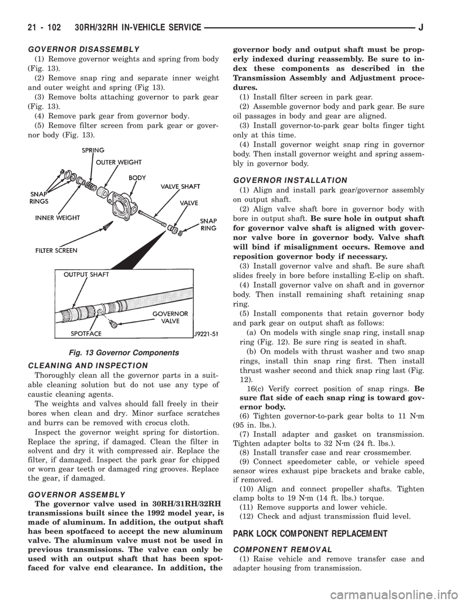
(1) Remove governor weights and spring from body
(Fig. 13).
(2) Remove snap ring and separate inner weight
and outer weight and spring (Fig 13).
(3) Remove bolts attaching governor to park gear
(Fig. 13).
(4) Remove park gear from governor body.
(5) Remove filter screen from park gear or gover-
nor body (Fig. 13).
CLEANING AND INSPECTION
Thoroughly clean all the governor parts in a suit-
able cleaning solution but do not use any type of
caustic cleaning agents.
The weights and valves should fall freely in their
bores when clean and dry. Minor surface scratches
and burrs can be removed with crocus cloth.
Inspect the governor weight spring for distortion.
Replace the spring, if damaged. Clean the filter in
solvent and dry it with compressed air. Replace the
filter, if damaged. Inspect the park gear for chipped
or worn gear teeth or damaged ring grooves. Replace
the gear, if damaged.
GOVERNOR ASSEMBLY
The governor valve used in 30RH/31RH/32RH
transmissions built since the 1992 model year, is
made of aluminum. In addition, the output shaft
has been spotfaced to accept the new aluminum
valve. The aluminum valve must not be used in
previous transmissions. The valve can only be
used with an output shaft that has been spot-
faced for valve end clearance. In addition, thegovernor body and output shaft must be prop-
erly indexed during reassembly. Be sure to in-
dex these components as described in the
Transmission Assembly and Adjustment proce-
dures.
(1) Install filter screen in park gear.
(2) Assemble governor body and park gear. Be sure
oil passages in body and gear are aligned.
(3) Install governor-to-park gear bolts finger tight
only at this time.
(4) Install governor weight snap ring in governor
body. Then install governor weight and spring assem-
bly in governor body.
GOVERNOR INSTALLATION
(1) Align and install park gear/governor assembly
on output shaft.
(2) Align valve shaft bore in governor body with
bore in output shaft.Be sure hole in output shaft
for governor valve shaft is aligned with gover-
nor valve bore in governor body. Valve shaft
will bind if misalignment occurs. Remove and
reposition governor body if necessary.
(3) Install governor valve and shaft. Be sure shaft
slides freely in bore before installing E-clip on shaft.
(4) Install governor valve on shaft and in governor
body. Then install remaining shaft retaining snap
ring.
(5) Install components that retain governor body
and park gear on output shaft as follows:
(a) On models with single snap ring, install snap
ring (Fig. 12). Be sure ring is seated in shaft.
(b) On models with thrust washer and two snap
rings, install thin snap ring first. Then install
thrust washer second and thick snap ring last (Fig.
12).
16(c) Verify correct position of snap rings.Be
sure flat side of each snap ring is toward gov-
ernor body.
(6) Tighten governor-to-park gear bolts to 11 Nzm
(95 in. lbs.).
(7) Install adapter and gasket on transmission.
Tighten adapter bolts to 32 Nzm (24 ft. lbs.).
(8) Install transfer case and rear crossmember.
(9) Connect speedometer cable, or vehicle speed
sensor wires exhaust pipe brackets and brake cable,
if removed.
(10) Align and connect propeller shafts. Tighten
clamp bolts to 19 Nzm (14 ft. lbs.) torque.
(11) Remove supports and lower vehicle.
(12) Check and adjust transmission fluid level.
PARK LOCK COMPONENT REPLACEMENT
COMPONENT REMOVAL
(1) Raise vehicle and remove transfer case and
adapter housing from transmission.
Fig. 13 Governor Components
21 - 102 30RH/32RH IN-VEHICLE SERVICEJ