1994 JEEP CHEROKEE sensor
[x] Cancel search: sensorPage 1284 of 1784
AW-4 IN-VEHICLE SERVICE
INDEX
page page
Accumulator Pistons and Springs........... 179
Adapter Housing Seal Replacement.......... 182
Checking Fluid Level and Condition.......... 173
Manual Valve Shaft Seal Replacement....... 178
Park Interlock Cable Adjustment............ 186
Park Rod and Pawl Service................ 181
Park/Neutral Position Switch............... 173
Second Coast Brake Servo................ 181
Shift Cable Adjustment................... 186
Speed Sensor.......................... 182Speed Sensor RotorÐSpeedometer Drive Gear . 183
Throttle Position Sensor (TPS) Service....... 184
Transmission Control Module (TCM) Service . . . 173
Transmission Cooler Line Fittings........... 187
Transmission Cooler Service............... 187
Transmission Throttle Cable Adjustment....... 185
Transmission Throttle Cable Replacement..... 184
Transmission Valve Body Installation......... 177
Transmission Valve Body Removal.......... 176
Transmission Valve Body Solenoids.......... 175
CHECKING FLUID LEVEL AND CONDITION
Recommended fluid for AW-4 transmissions is Mo-
par Dexron IIE/Mercon. Mopar Dexron II may be
used if Mercon fluid is not readily available.
CHECKING FLUID LEVEL
(1) Be sure transmission fluid is at normal operat-
ing temperature. Normal operating temperature is
reached after approximately 15 miles (25 km) of op-
eration.
(2) Position vehicle on level surface. This is impor-
tant for an accurate fluid level check.
(3) Shift transmission through all gear ranges and
back to Park.
(4) Apply parking brakes.
(5) Verify that transmission is in Park.
(6) Wipe off dipstick handle to prevent dirt from
entering fill tube. Then remove dipstick and check
fluid level and condition.
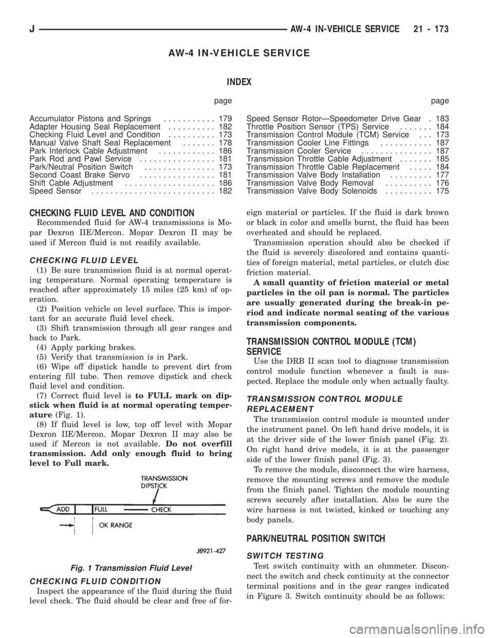
(7) Correct fluid level isto FULL mark on dip-
stick when fluid is at normal operating temper-
ature(Fig. 1).
(8) If fluid level is low, top off level with Mopar
Dexron IIE/Mercon. Mopar Dexron II may also be
used if Mercon is not available.Do not overfill
transmission. Add only enough fluid to bring
level to Full mark.
CHECKING FLUID CONDITION
Inspect the appearance of the fluid during the fluid
level check. The fluid should be clear and free of for-eign material or particles. If the fluid is dark brown
or black in color and smells burnt, the fluid has been
overheated and should be replaced.
Transmission operation should also be checked if
the fluid is severely discolored and contains quanti-
ties of foreign material, metal particles, or clutch disc
friction material.
A small quantity of friction material or metal
particles in the oil pan is normal. The particles
are usually generated during the break-in pe-
riod and indicate normal seating of the various
transmission components.
TRANSMISSION CONTROL MODULE (TCM)
SERVICE
Use the DRB II scan tool to diagnose transmission
control module function whenever a fault is sus-
pected. Replace the module only when actually faulty.
TRANSMISSION CONTROL MODULE
REPLACEMENT
The transmission control module is mounted under
the instrument panel. On left hand drive models, it is
at the driver side of the lower finish panel (Fig. 2).
On right hand drive models, it is at the passenger
side of the lower finish panel (Fig. 3).
To remove the module, disconnect the wire harness,
remove the mounting screws and remove the module
from the finish panel. Tighten the module mounting
screws securely after installation. Also be sure the
wire harness is not twisted, kinked or touching any
body panels.
PARK/NEUTRAL POSITION SWITCH
SWITCH TESTING
Test switch continuity with an ohmmeter. Discon-
nect the switch and check continuity at the connector
terminal positions and in the gear ranges indicated
in Figure 3. Switch continuity should be as follows:Fig. 1 Transmission Fluid Level
JAW-4 IN-VEHICLE SERVICE 21 - 173
Page 1293 of 1784
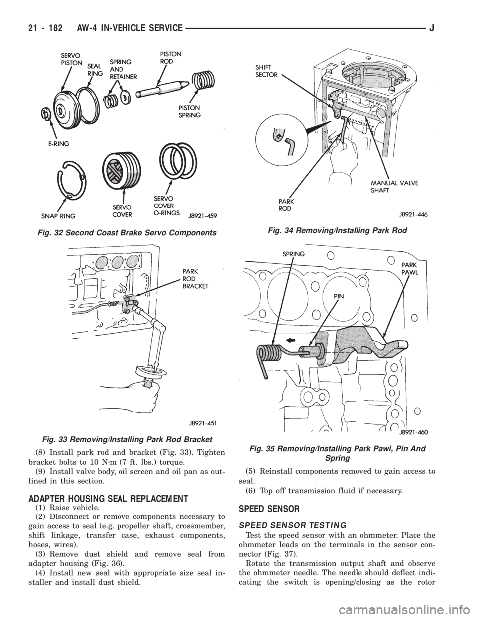
(8) Install park rod and bracket (Fig. 33). Tighten
bracket bolts to 10 Nzm (7 ft. lbs.) torque.
(9) Install valve body, oil screen and oil pan as out-
lined in this section.
ADAPTER HOUSING SEAL REPLACEMENT
(1) Raise vehicle.
(2) Disconnect or remove components necessary to
gain access to seal (e.g. propeller shaft, crossmember,
shift linkage, transfer case, exhaust components,
hoses, wires).
(3) Remove dust shield and remove seal from
adapter housing (Fig. 36).
(4) Install new seal with appropriate size seal in-
staller and install dust shield.(5) Reinstall components removed to gain access to
seal.
(6) Top off transmission fluid if necessary.SPEED SENSOR
SPEED SENSOR TESTING
Test the speed sensor with an ohmmeter. Place the
ohmmeter leads on the terminals in the sensor con-
nector (Fig. 37).
Rotate the transmission output shaft and observe
the ohmmeter needle. The needle should deflect indi-
cating the switch is opening/closing as the rotor
Fig. 34 Removing/Installing Park Rod
Fig. 35 Removing/Installing Park Pawl, Pin And
Spring
Fig. 32 Second Coast Brake Servo Components
Fig. 33 Removing/Installing Park Rod Bracket
21 - 182 AW-4 IN-VEHICLE SERVICEJ
Page 1294 of 1784
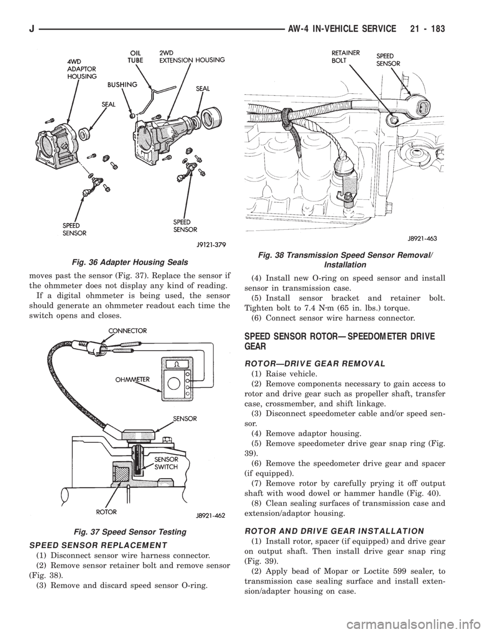
moves past the sensor (Fig. 37). Replace the sensor if
the ohmmeter does not display any kind of reading.
If a digital ohmmeter is being used, the sensor
should generate an ohmmeter readout each time the
switch opens and closes.
SPEED SENSOR REPLACEMENT
(1) Disconnect sensor wire harness connector.
(2) Remove sensor retainer bolt and remove sensor
(Fig. 38).
(3) Remove and discard speed sensor O-ring.(4) Install new O-ring on speed sensor and install
sensor in transmission case.
(5) Install sensor bracket and retainer bolt.
Tighten bolt to 7.4 Nzm (65 in. lbs.) torque.
(6) Connect sensor wire harness connector.
SPEED SENSOR ROTORÐSPEEDOMETER DRIVE
GEAR
ROTORÐDRIVE GEAR REMOVAL
(1) Raise vehicle.
(2) Remove components necessary to gain access to
rotor and drive gear such as propeller shaft, transfer
case, crossmember, and shift linkage.
(3) Disconnect speedometer cable and/or speed sen-
sor.
(4) Remove adaptor housing.
(5) Remove speedometer drive gear snap ring (Fig.
39).
(6) Remove the speedometer drive gear and spacer
(if equipped).
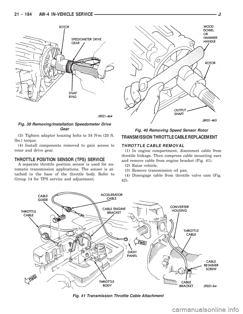
(7) Remove rotor by carefully prying it off output
shaft with wood dowel or hammer handle (Fig. 40).
(8) Clean sealing surfaces of transmission case and
extension/adaptor housing.
ROTOR AND DRIVE GEAR INSTALLATION
(1) Install rotor, spacer (if equipped) and drive gear
on output shaft. Then install drive gear snap ring
(Fig. 39).
(2) Apply bead of Mopar or Loctite 599 sealer, to
transmission case sealing surface and install exten-
sion/adapter housing on case.
Fig. 36 Adapter Housing Seals
Fig. 37 Speed Sensor Testing
Fig. 38 Transmission Speed Sensor Removal/
Installation
JAW-4 IN-VEHICLE SERVICE 21 - 183
Page 1295 of 1784
(3) Tighten adaptor housing bolts to 34 Nzm (25 ft.
lbs.) torque.
(4) Install components removed to gain access to
rotor and drive gear.
THROTTLE POSITION SENSOR (TPS) SERVICE
A separate throttle position sensor is used for au-
tomatic transmission applications. The sensor is at-
tached to the base of the throttle body. Refer to
Group 14 for TPS service and adjustment.
TRANSMISSION THROTTLE CABLE REPLACEMENT
THROTTLE CABLE REMOVAL
(1) In engine compartment, disconnect cable from
throttle linkage. Then compress cable mounting ears
and remove cable from engine bracket (Fig. 41).
(2) Raise vehicle.
(3) Remove transmission oil pan.
(4) Disengage cable from throttle valve cam (Fig.
42).
Fig. 41 Transmission Throttle Cable Attachment
Fig. 40 Removing Speed Sensor Rotor
Fig. 39 Removing/Installation Speedometer Drive
Gear
21 - 184 AW-4 IN-VEHICLE SERVICEJ
Page 1300 of 1784
AW-4 TRANSMISSION REMOVAL AND INSTALLATION
INDEX
page page
Oil Pump Seal Replacement............... 189
Torque Converter Stator Clutch Inspection..... 189Transmission and Torque Converter Installation . 190
Transmission and Torque Converter Removal . . 189
TRANSMISSION AND TORQUE CONVERTER
REMOVAL
(1) Raise vehicle.
(2) Drain transmission fluid and reinstall oil pan
drain plug.
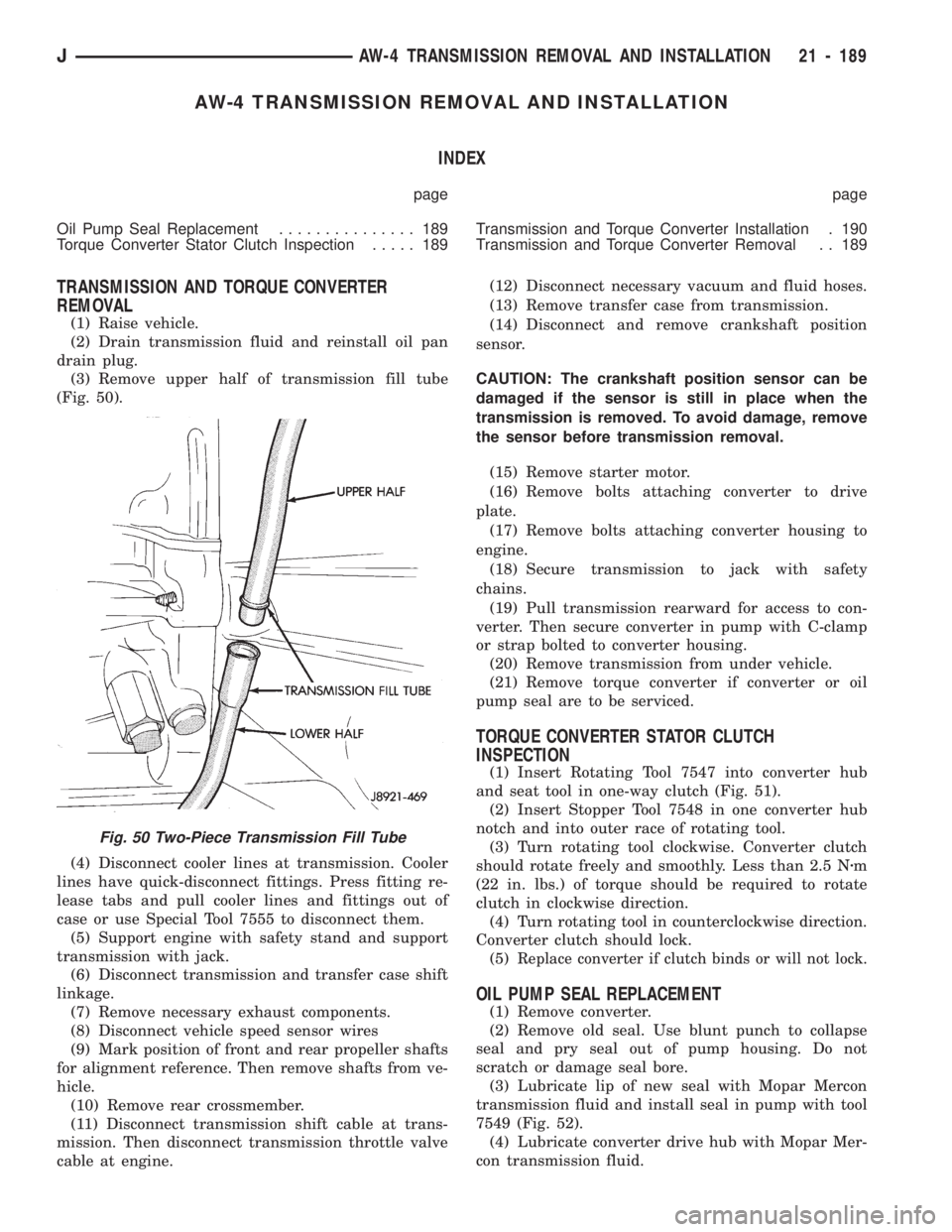
(3) Remove upper half of transmission fill tube
(Fig. 50).
(4) Disconnect cooler lines at transmission. Cooler
lines have quick-disconnect fittings. Press fitting re-
lease tabs and pull cooler lines and fittings out of
case or use Special Tool 7555 to disconnect them.
(5) Support engine with safety stand and support
transmission with jack.
(6) Disconnect transmission and transfer case shift
linkage.
(7) Remove necessary exhaust components.
(8) Disconnect vehicle speed sensor wires
(9) Mark position of front and rear propeller shafts
for alignment reference. Then remove shafts from ve-
hicle.
(10) Remove rear crossmember.
(11) Disconnect transmission shift cable at trans-
mission. Then disconnect transmission throttle valve
cable at engine.(12) Disconnect necessary vacuum and fluid hoses.
(13) Remove transfer case from transmission.
(14) Disconnect and remove crankshaft position
sensor.
CAUTION: The crankshaft position sensor can be
damaged if the sensor is still in place when the
transmission is removed. To avoid damage, remove
the sensor before transmission removal.
(15) Remove starter motor.
(16) Remove bolts attaching converter to drive
plate.
(17) Remove bolts attaching converter housing to
engine.
(18) Secure transmission to jack with safety
chains.
(19) Pull transmission rearward for access to con-
verter. Then secure converter in pump with C-clamp
or strap bolted to converter housing.
(20) Remove transmission from under vehicle.
(21) Remove torque converter if converter or oil
pump seal are to be serviced.
TORQUE CONVERTER STATOR CLUTCH
INSPECTION
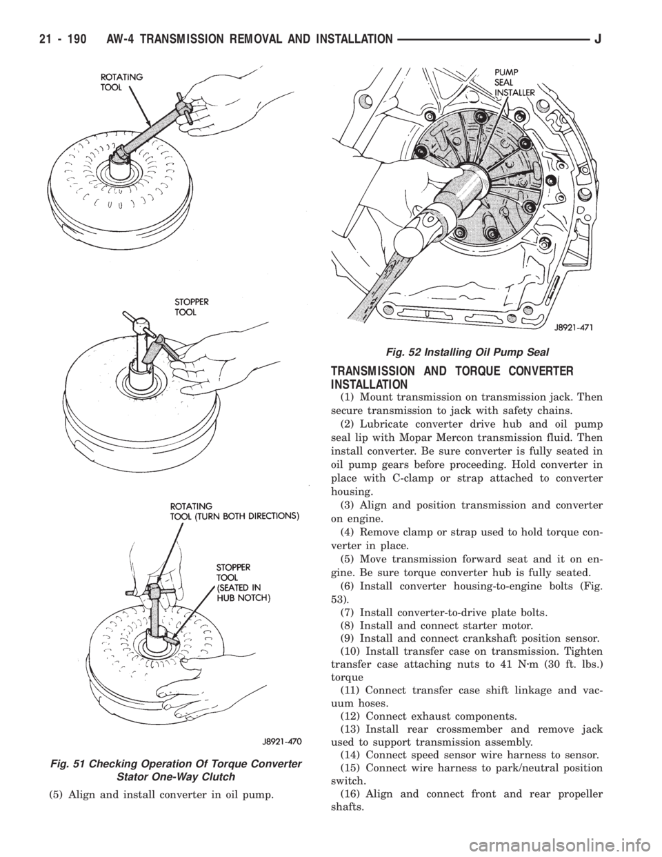
(1) Insert Rotating Tool 7547 into converter hub
and seat tool in one-way clutch (Fig. 51).
(2) Insert Stopper Tool 7548 in one converter hub
notch and into outer race of rotating tool.
(3) Turn rotating tool clockwise. Converter clutch
should rotate freely and smoothly. Less than 2.5 Nzm
(22 in. lbs.) of torque should be required to rotate
clutch in clockwise direction.
(4) Turn rotating tool in counterclockwise direction.
Converter clutch should lock.
(5)
Replace converter if clutch binds or will not lock.
OIL PUMP SEAL REPLACEMENT
(1) Remove converter.
(2) Remove old seal. Use blunt punch to collapse
seal and pry seal out of pump housing. Do not
scratch or damage seal bore.
(3) Lubricate lip of new seal with Mopar Mercon
transmission fluid and install seal in pump with tool
7549 (Fig. 52).
(4) Lubricate converter drive hub with Mopar Mer-
con transmission fluid.
Fig. 50 Two-Piece Transmission Fill Tube
JAW-4 TRANSMISSION REMOVAL AND INSTALLATION 21 - 189
Page 1301 of 1784
(5) Align and install converter in oil pump.
TRANSMISSION AND TORQUE CONVERTER
INSTALLATION
(1) Mount transmission on transmission jack. Then
secure transmission to jack with safety chains.
(2) Lubricate converter drive hub and oil pump
seal lip with Mopar Mercon transmission fluid. Then
install converter. Be sure converter is fully seated in
oil pump gears before proceeding. Hold converter in
place with C-clamp or strap attached to converter
housing.
(3) Align and position transmission and converter
on engine.
(4) Remove clamp or strap used to hold torque con-
verter in place.
(5) Move transmission forward seat and it on en-
gine. Be sure torque converter hub is fully seated.
(6)
Install converter housing-to-engine bolts (Fig.
53).
(7) Install converter-to-drive plate bolts.
(8) Install and connect starter motor.
(9) Install and connect crankshaft position sensor.
(10) Install transfer case on transmission. Tighten
transfer case attaching nuts to 41 Nzm (30 ft. lbs.)
torque
(11) Connect transfer case shift linkage and vac-
uum hoses.
(12) Connect exhaust components.
(13) Install rear crossmember and remove jack
used to support transmission assembly.
(14) Connect speed sensor wire harness to sensor.
(15) Connect wire harness to park/neutral position
switch.
(16) Align and connect front and rear propeller
shafts.
Fig. 51 Checking Operation Of Torque Converter
Stator One-Way Clutch
Fig. 52 Installing Oil Pump Seal
21 - 190 AW-4 TRANSMISSION REMOVAL AND INSTALLATIONJ
Page 1303 of 1784
AW-4 TRANSMISSION OVERHAUL
INDEX
page page
Cleaning and Inspection................... 76
Direct Clutch Overhaul................... 219
First-Reverse Brake Piston and Transmission
Case Overhaul........................ 237
Forward Clutch Overhaul.................. 223
Front Planetary Gear Overhaul............. 228
Manual Valve Shaft Overhaul.............. 205
Oil Pump Overhaul...................... 206
Overdrive Planetary Gear and Clutch Overhaul . 209Overdrive Support Overhaul................ 216
Overhaul Service Tools................... 192
Rear Planetary, No. 2 One-Way Clutch and
Output Shaft Overhaul.................. 100
Second Brake Overhaul................... 100
Sun Gear and No. 1 One-Way Clutch Overhaul . 99
Transmission Assembly and Adjustment....... 255
Transmission Disassembly................. 192
Transmission Valve Body Overhaul.......... 101
OVERHAUL SERVICE TOOLS
The special tools needed to overhaul the AW-4
transmission are provided in Tool Kit 6294. However,
Pressure Test Port Adapter 7554 is not included in
this kit and must be ordered separately. The over-
haul tool kit and test port adapter are available
through the parts division and dealer special tool
program.
TRANSMISSION DISASSEMBLY
(1) Remove torque converter.
(2) Remove lower half of filler tube if not previ-
ously removed.
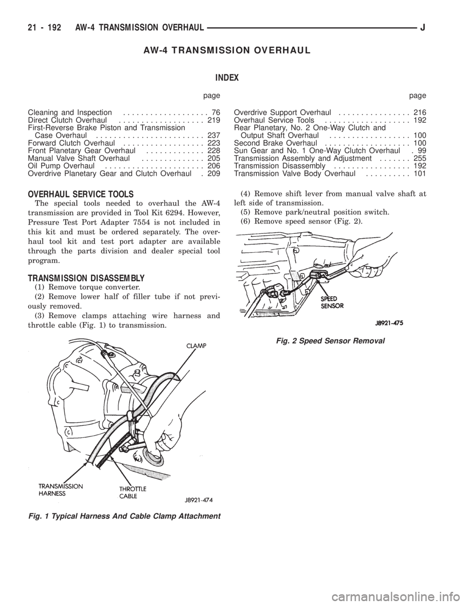
(3) Remove clamps attaching wire harness and
throttle cable (Fig. 1) to transmission.(4) Remove shift lever from manual valve shaft at
left side of transmission.
(5) Remove park/neutral position switch.
(6) Remove speed sensor (Fig. 2).
Fig. 1 Typical Harness And Cable Clamp Attachment
Fig. 2 Speed Sensor Removal
21 - 192 AW-4 TRANSMISSION OVERHAULJ
Page 1304 of 1784
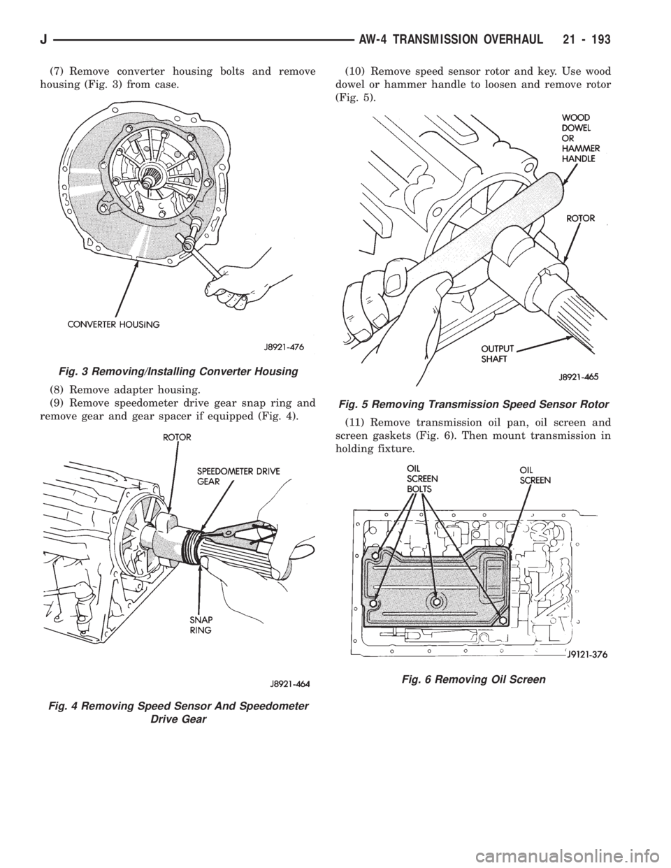
(7) Remove converter housing bolts and remove
housing (Fig. 3) from case.
(8) Remove adapter housing.
(9) Remove speedometer drive gear snap ring and
remove gear and gear spacer if equipped (Fig. 4).(10) Remove speed sensor rotor and key. Use wood
dowel or hammer handle to loosen and remove rotor
(Fig. 5).
(11) Remove transmission oil pan, oil screen and
screen gaskets (Fig. 6). Then mount transmission in
holding fixture.
Fig. 3 Removing/Installing Converter Housing
Fig. 4 Removing Speed Sensor And Speedometer
Drive Gear
Fig. 5 Removing Transmission Speed Sensor Rotor
Fig. 6 Removing Oil Screen
JAW-4 TRANSMISSION OVERHAUL 21 - 193