1994 JEEP CHEROKEE ignition
[x] Cancel search: ignitionPage 421 of 1784
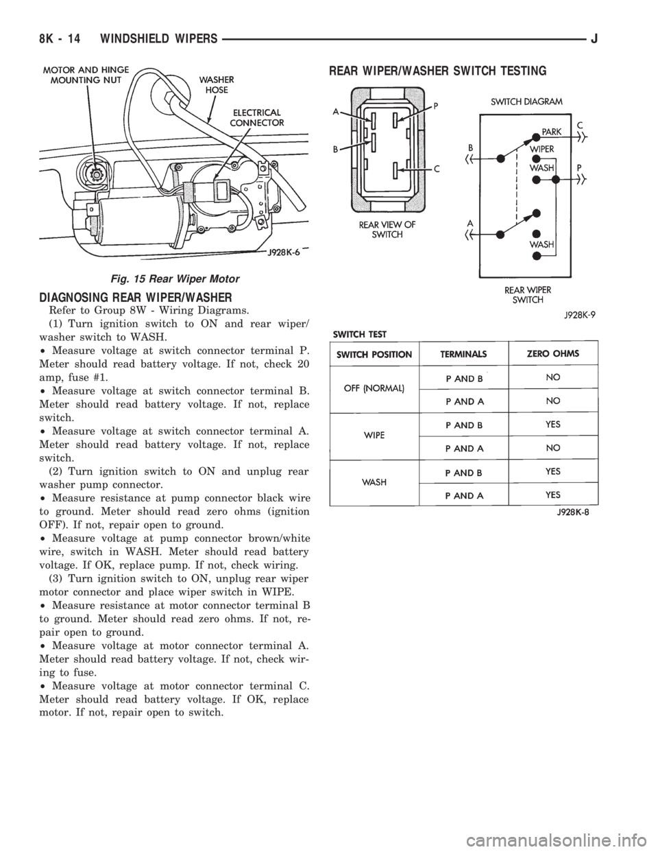
DIAGNOSING REAR WIPER/WASHER
Refer to Group 8W - Wiring Diagrams.
(1) Turn ignition switch to ON and rear wiper/
washer switch to WASH.
²Measure voltage at switch connector terminal P.
Meter should read battery voltage. If not, check 20
amp, fuse #1.
²Measure voltage at switch connector terminal B.
Meter should read battery voltage. If not, replace
switch.
²Measure voltage at switch connector terminal A.
Meter should read battery voltage. If not, replace
switch.
(2) Turn ignition switch to ON and unplug rear
washer pump connector.
²Measure resistance at pump connector black wire
to ground. Meter should read zero ohms (ignition
OFF). If not, repair open to ground.
²Measure voltage at pump connector brown/white
wire, switch in WASH. Meter should read battery
voltage. If OK, replace pump. If not, check wiring.
(3) Turn ignition switch to ON, unplug rear wiper
motor connector and place wiper switch in WIPE.
²Measure resistance at motor connector terminal B
to ground. Meter should read zero ohms. If not, re-
pair open to ground.
²Measure voltage at motor connector terminal A.
Meter should read battery voltage. If not, check wir-
ing to fuse.
²Measure voltage at motor connector terminal C.
Meter should read battery voltage. If OK, replace
motor. If not, repair open to switch.
REAR WIPER/WASHER SWITCH TESTING
Fig. 15 Rear Wiper Motor
8K - 14 WINDSHIELD WIPERSJ
Page 422 of 1784
WIPER CONTROL SWITCH REPLACEMENT
(1) Disconnect negative cable from battery.
(2) Remove horn button with a push and turn mo-
tion.
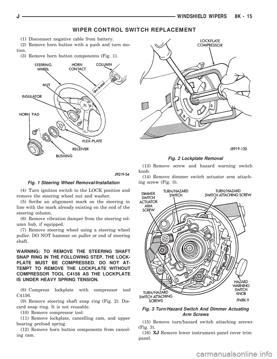
(3) Remove horn button components (Fig. 1).
(4) Turn ignition switch to the LOCK position and
remove the steering wheel nut and washer.
(5) Scribe an alignment mark on the steering in
line with the mark already existing on the end of the
steering column.
(6) Remove vibration damper from the steering col-
umn hub, if equipped.
(7) Remove steering wheel using a steering wheel
puller. DO NOT hammer on puller or end of steering
shaft.
WARNING: TO REMOVE THE STEERING SHAFT
SNAP RING IN THE FOLLOWING STEP, THE LOCK-
PLATE MUST BE COMPRESSED. DO NOT AT-
TEMPT TO REMOVE THE LOCKPLATE WITHOUT
COMPRESSOR TOOL C4156 AS THE LOCKPLATE
IS UNDER HEAVY SPRING TENSION.
(8) Compress lockplate with compressor tool
C4156.
(9) Remove steering shaft snap ring (Fig. 2). Dis-
card snap ring. It is not reusable.
(10) Remove compressor tool.
(11) Remove lockplate, cancelling cam, and upper
bearing preload spring.
(12) Remove horn button components from cancel-
ing cam.(13) Remove screw and hazard warning switch
knob.
(14) Remove dimmer switch actuator arm attach-
ing screw (Fig. 3).
(15) Remove turn/hazard switch attaching screws
(Fig. 3).
(16)XJRemove lower instrument panel cover trim
panel.
Fig. 1 Steering Wheel Removal/Installation
Fig. 2 Lockplate Removal
Fig. 3 Turn/Hazard Switch And Dimmer Actuating
Arm Screws
JWINDSHIELD WIPERS 8K - 15
Page 424 of 1784
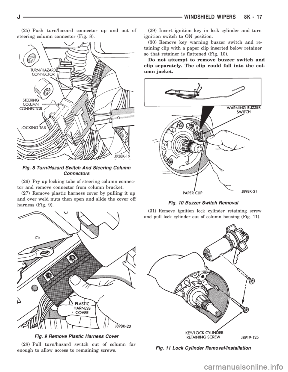
(25) Push turn/hazard connector up and out of
steering column connector (Fig. 8).
(26) Pry up locking tabs of steering column connec-
tor and remove connector from column bracket.
(27) Remove plastic harness cover by pulling it up
and over weld nuts then open and slide the cover off
harness (Fig. 9).
(28) Pull turn/hazard switch out of column far
enough to allow access to remaining screws.(29) Insert ignition key in lock cylinder and turn
ignition switch to ON position.
(30) Remove key warning buzzer switch and re-
taining clip with a paper clip inserted below retainer
so that retainer is flattened (Fig. 10).
Do not attempt to remove buzzer switch and
clip separately. The clip could fall into the col-
umn jacket.
(31) Remove ignition lock cylinder retaining screw
and pull lock cylinder out of column housing (Fig. 11).
Fig. 8 Turn/Hazard Switch And Steering Column
Connectors
Fig. 9 Remove Plastic Harness Cover
Fig. 10 Buzzer Switch Removal
Fig. 11 Lock Cylinder Removal/Installation
JWINDSHIELD WIPERS 8K - 17
Page 442 of 1784
INSTALLATIONÐYJ VEHICLES
(1) Position the fog lamp switch in the instrument
panel cavity and connect the wire harness connector
to the switch.
(2) Install the fog lamp switch retaining screws.
Tighten the screws securely.
(3) Position the I/P shroud under the steering col-
umn.
(4) Slide the indicator panel holding tabs into the
shroud notches.
(5) Place the assembled I/P shroud over the indica-
tor lamp foam gasket.
The foam gasket located on the back side of
the indicator panel overlay is fragile. If it is ei-
ther torn or distorted, replace it.
(6) Install and tighten the indicator panel retain-
ing screws.
(7) Install the remaining shroud screws. Tighten
the screws securely.
(8) Connect the battery negative cable.
FOG LAMP REPLACEMENT
REMOVALÐXJ VEHICLES
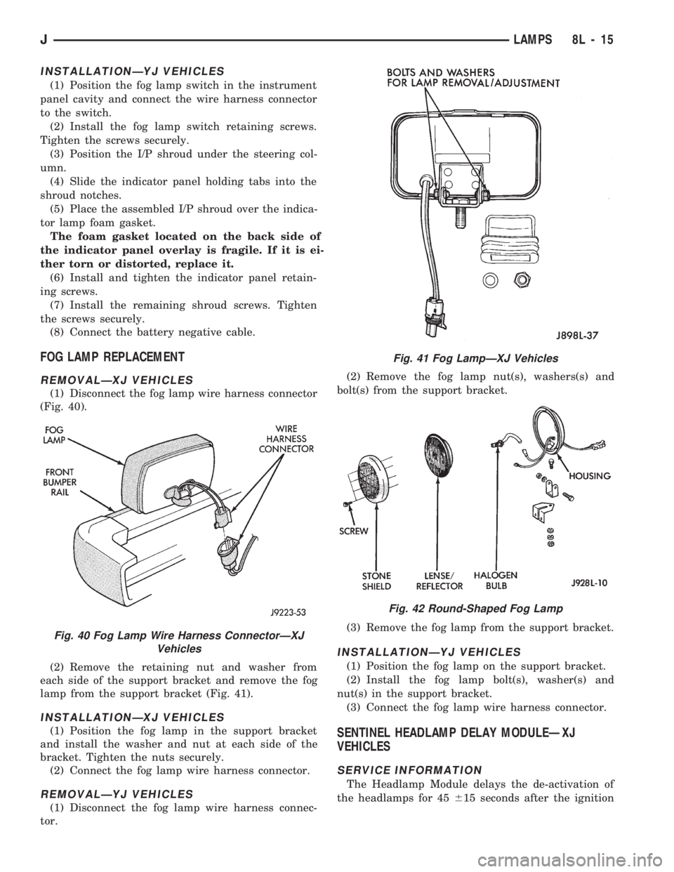
(1) Disconnect the fog lamp wire harness connector
(Fig. 40).
(2) Remove the retaining nut and washer from
each side of the support bracket and remove the fog
lamp from the support bracket (Fig. 41).
INSTALLATIONÐXJ VEHICLES
(1) Position the fog lamp in the support bracket
and install the washer and nut at each side of the
bracket. Tighten the nuts securely.
(2) Connect the fog lamp wire harness connector.
REMOVALÐYJ VEHICLES
(1) Disconnect the fog lamp wire harness connec-
tor.(2) Remove the fog lamp nut(s), washers(s) and
bolt(s) from the support bracket.
(3) Remove the fog lamp from the support bracket.
INSTALLATIONÐYJ VEHICLES
(1) Position the fog lamp on the support bracket.
(2) Install the fog lamp bolt(s), washer(s) and
nut(s) in the support bracket.
(3) Connect the fog lamp wire harness connector.
SENTINEL HEADLAMP DELAY MODULEÐXJ
VEHICLES
SERVICE INFORMATION
The Headlamp Module delays the de-activation of
the headlamps for 45615 seconds after the ignition
Fig. 40 Fog Lamp Wire Harness ConnectorÐXJ
Vehicles
Fig. 41 Fog LampÐXJ Vehicles
Fig. 42 Round-Shaped Fog Lamp
JLAMPS 8L - 15
Page 443 of 1784
switch is turned OFF. The driver engages the module
by turning the ignition switch OFF, then turning the
headlamps OFF.
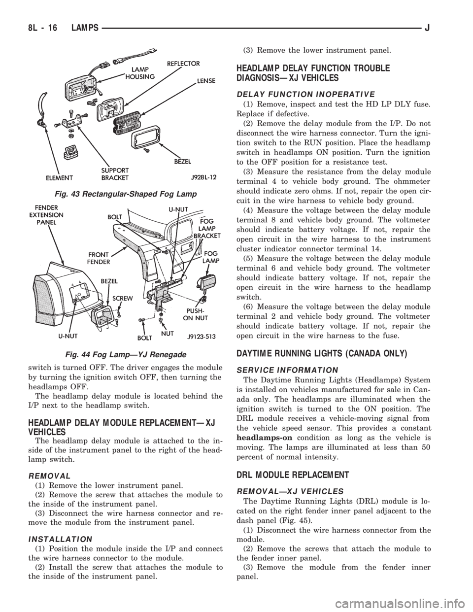
The headlamp delay module is located behind the
I/P next to the headlamp switch.
HEADLAMP DELAY MODULE REPLACEMENTÐXJ
VEHICLES
The headlamp delay module is attached to the in-
side of the instrument panel to the right of the head-
lamp switch.
REMOVAL
(1) Remove the lower instrument panel.
(2) Remove the screw that attaches the module to
the inside of the instrument panel.
(3) Disconnect the wire harness connector and re-
move the module from the instrument panel.
INSTALLATION
(1) Position the module inside the I/P and connect
the wire harness connector to the module.
(2) Install the screw that attaches the module to
the inside of the instrument panel.(3) Remove the lower instrument panel.
HEADLAMP DELAY FUNCTION TROUBLE
DIAGNOSISÐXJ VEHICLES
DELAY FUNCTION INOPERATIVE
(1) Remove, inspect and test the HD LP DLY fuse.
Replace if defective.
(2) Remove the delay module from the I/P. Do not
disconnect the wire harness connector. Turn the igni-
tion switch to the RUN position. Place the headlamp
switch in headlamps ON position. Turn the ignition
to the OFF position for a resistance test.
(3) Measure the resistance from the delay module
terminal 4 to vehicle body ground. The ohmmeter
should indicate zero ohms. If not, repair the open cir-
cuit in the wire harness to vehicle body ground.
(4) Measure the voltage between the delay module
terminal 8 and vehicle body ground. The voltmeter
should indicate battery voltage. If not, repair the
open circuit in the wire harness to the instrument
cluster indicator connector terminal 14.
(5) Measure the voltage between the delay module
terminal 6 and vehicle body ground. The voltmeter
should indicate battery voltage. If not, repair the
open circuit in the wire harness to the headlamp
switch.
(6) Measure the voltage between the delay module
terminal 2 and vehicle body ground. The voltmeter
should indicate battery voltage. If not, repair the
open circuit in the wire harness to the fuse.
DAYTIME RUNNING LIGHTS (CANADA ONLY)
SERVICE INFORMATION
The Daytime Running Lights (Headlamps) System
is installed on vehicles manufactured for sale in Can-
ada only. The headlamps are illuminated when the
ignition switch is turned to the ON position. The
DRL module receives a vehicle-moving signal from
the vehicle speed sensor. This provides a constant
headlamps-oncondition as long as the vehicle is
moving. The lamps are illuminated at less than 50
percent of normal intensity.
DRL MODULE REPLACEMENT
REMOVALÐXJ VEHICLES
The Daytime Running Lights (DRL) module is lo-
cated on the right fender inner panel adjacent to the
dash panel (Fig. 45).
(1) Disconnect the wire harness connector from the
module.
(2) Remove the screws that attach the module to
the fender inner panel.
(3) Remove the module from the fender inner
panel.
Fig. 43 Rectangular-Shaped Fog Lamp
Fig. 44 Fog LampÐYJ Renegade
8L - 16 LAMPSJ
Page 448 of 1784
switches, the keyless entry system, and the ignition
switch (when in the RUN position). When correct in-
put is received, the entry module timer immediately
begins the timing-out process. The timing-out process
requires approximately 3066 seconds.
The illuminated entry system also operates
when a door is opened to exit the vehicle. When
the door is closed the interior illumination will
continue for the remaining portion of the 30 sec-
onds.
ILLUMINATED ENTRY SYSTEM TROUBLE
DIAGNOSIS
The Illuminated Entry System relay is located on a
bracket behind the instrument panel.
(1) Ensure that the ignition switch is in the Off po-
sition.
(2) Open and immediately close the driver-side
door. The interior courtesy lamps should immediately
illuminate.
(3) Open driver-side door, enter the vehicle, close
the door and turn the ignition switch to the RUN po-sition. The courtesy lamps should go out. Turn the
ignition switch to the OFF position before exiting ve-
hicle.
(4) When exiting the vehicle, the courtesy lamps
should remain illuminated after the door is closed.
(5) From outside the vehicle, open and close the
passenger-side door. The courtesy lamps should illu-
minate.
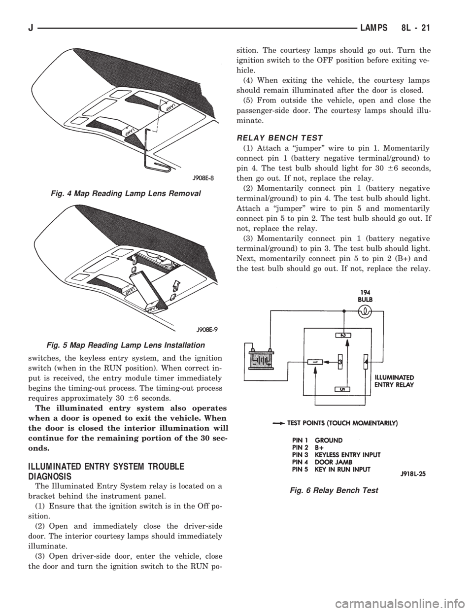
RELAY BENCH TEST
(1) Attach a ``jumper'' wire to pin 1. Momentarily
connect pin 1 (battery negative terminal/ground) to
pin 4. The test bulb should light for 3066 seconds,
then go out. If not, replace the relay.
(2) Momentarily connect pin 1 (battery negative
terminal/ground) to pin 4. The test bulb should light.
Attach a ``jumper'' wire to pin 5 and momentarily
connect pin 5 to pin 2. The test bulb should go out. If
not, replace the relay.
(3) Momentarily connect pin 1 (battery negative
terminal/ground) to pin 3. The test bulb should light.
Next, momentarily connect pin 5 to pin 2 (B+) and
the test bulb should go out. If not, replace the relay.
Fig. 4 Map Reading Lamp Lens Removal
Fig. 5 Map Reading Lamp Lens Installation
Fig. 6 Relay Bench Test
JLAMPS 8L - 21
Page 452 of 1784
REAR WINDOW DEFOGGER
CONTENTS
page page
GENERAL.............................. 1
XJ .................................... 4YJ .................................... 4
GENERAL
INDEX
page page
Diagnosis............................... 2
Rear Window Defogger Grid Repair........... 2Rear Window Defogger Grid Test............. 1
Switch Testing............................ 2
Using heating elements bonded to the rear window
glass, the rear defogger will clear condensation, frost
and light snow coverings from the rear window.
The horizontal grid lines and vertical bus bar lines,
printed and baked on inside surface of the rear win-
dow glass, comprise an electrical circuit. The electri-
cally conductive lines are composed of a silver-
ceramic material which when baked on glass
becomes bonded to the glass and is highly resistant
to abrasion.
The electrical current required to produce the heat
in the grid is supplied through a relay and driver op-
erated switch. When the switch is momentarily de-
pressed, the relay senses a voltage change. This
voltage change causes the relay to change state and
complete a circuit to energize the relay. Once the re-
lay energizes, the contacts close connecting the grid
to battery power.
On the XJ, the power circuit to the grid is pro-
tected by the 25 amp, #18 fuse in the fuse box.
Power for fuse #18 comes from the power distribu-
tion center, fuse #F10. Power for the relay is pro-
tected by the 20 amp, #8 fuse located in the fuse box.
On the YJ, the grid is protected by a 25 amp #6
fuse, located in the fuse box. Power for the relay is
protected by 15 amp #9 fuse, located in the fuse box.
To defog the rear window, momentarily depress the
rocker switch. A light on the rocker switch will illu-
minate indicating that the defogger is operating.
If the ignition switch is ON the first activation of
the defog/defrost feature will last for 10 minutes.
Succeeding activations will last for 5 minutes unless
the ignition switch is turned OFF; then it will recy-
cle back to 10 minutes for the first activation.To stop defogger operation, momentarily push the
switch a second time.
CAUTION: Use care when washing the inside of the
rear window to prevent damage to the defogger
heating elements. Use a soft cloth and a mild wash-
ing solution. Wiping motions should be parallel to
the heating elements. Also, keep all objects a safe
distance from the window to prevent damaging the
heating elements.
REAR WINDOW DEFOGGER GRID TEST
It is possible, that a break may exist or occur in an
individual grid line resulting in no current flow
through the line. When a grid has an open circuit,
the area of glass normally cleared by that grid re-
mains fogged or iced unless, and until it is cleared by
the adjacent grids.
With the engine running at idle, push the rear
window defogger switch to the ON position and re-
lease. The pilot lamp in the rocker switch should
light, indicating defogger operation.
Using a 12-volt DC voltmeter, contact the positive
lead to the feed side vertical bus element on the in-
side surface of the glass. Contact the negative lead to
the ground side bus element. Meter should read be-
tween 11 and 13 volts. Connect the negative lead of
the voltmeter to a good ground; the meter reading
should be constant.
Keep the negative lead connected to ground. Use
the positive lead and carefully contact each grid at
the approximate centerline of the window.
JREAR WINDOW DEFOGGER 8N - 1
Page 453 of 1784
A voltage drop of one-half the full amount, approx-
imately 6 volts, indicates a good grid or closed cir-
cuit.
A voltage drop of 12 volts at the centerline indi-
cates a break in the grid between the positive volt-
meter lead and the ground.
No voltage drop (0 volts) at the centerline indicates
a break in the grid between the centerline and the
voltage source or lead.
The exact location of the break can be pinpointed
by moving positive voltmeter lead to the left or right
along grid. An abrupt change in the voltage reading
will be noticed. The break is at that point in the
grid.
REAR WINDOW DEFOGGER GRID REPAIR
Locate the broken or open grid.
Use the grid repair kit (available as a service part)
by using the following procedure:
(1) Mark the location of the broken or open grid on
the exterior surface of the glass using a suitable
marking pencil.
(2) Lightly rub the area to be repaired (inside the
rear window) using fine steel wool. Clean the area
with alcohol.
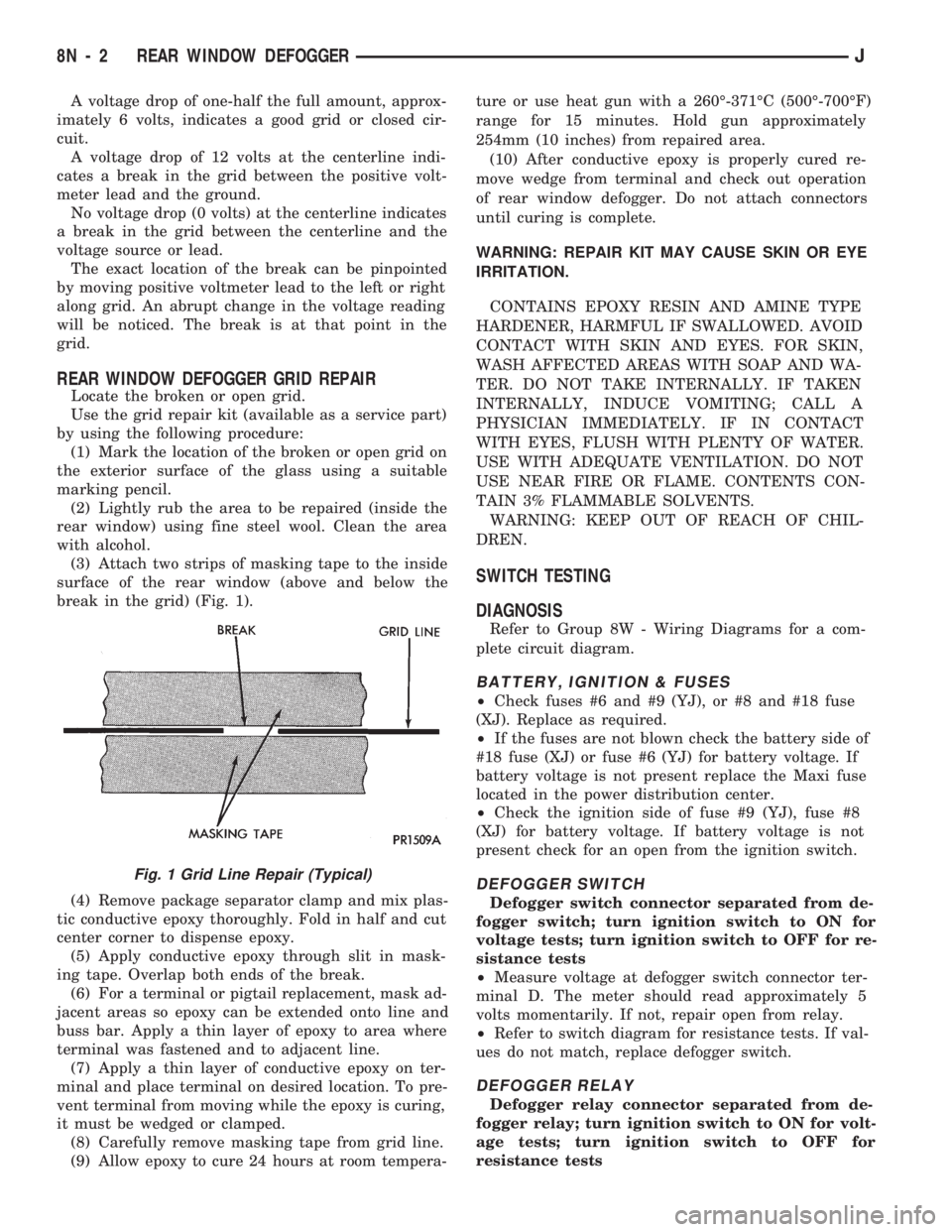
(3) Attach two strips of masking tape to the inside
surface of the rear window (above and below the
break in the grid) (Fig. 1).
(4) Remove package separator clamp and mix plas-
tic conductive epoxy thoroughly. Fold in half and cut
center corner to dispense epoxy.
(5) Apply conductive epoxy through slit in mask-
ing tape. Overlap both ends of the break.
(6) For a terminal or pigtail replacement, mask ad-
jacent areas so epoxy can be extended onto line and
buss bar. Apply a thin layer of epoxy to area where
terminal was fastened and to adjacent line.
(7) Apply a thin layer of conductive epoxy on ter-
minal and place terminal on desired location. To pre-
vent terminal from moving while the epoxy is curing,
it must be wedged or clamped.
(8) Carefully remove masking tape from grid line.
(9) Allow epoxy to cure 24 hours at room tempera-ture or use heat gun with a 260É-371ÉC (500É-700ÉF)
range for 15 minutes. Hold gun approximately
254mm (10 inches) from repaired area.
(10) After conductive epoxy is properly cured re-
move wedge from terminal and check out operation
of rear window defogger. Do not attach connectors
until curing is complete.
WARNING: REPAIR KIT MAY CAUSE SKIN OR EYE
IRRITATION.
CONTAINS EPOXY RESIN AND AMINE TYPE
HARDENER, HARMFUL IF SWALLOWED. AVOID
CONTACT WITH SKIN AND EYES. FOR SKIN,
WASH AFFECTED AREAS WITH SOAP AND WA-
TER. DO NOT TAKE INTERNALLY. IF TAKEN
INTERNALLY, INDUCE VOMITING; CALL A
PHYSICIAN IMMEDIATELY. IF IN CONTACT
WITH EYES, FLUSH WITH PLENTY OF WATER.
USE WITH ADEQUATE VENTILATION. DO NOT
USE NEAR FIRE OR FLAME. CONTENTS CON-
TAIN 3% FLAMMABLE SOLVENTS.
WARNING: KEEP OUT OF REACH OF CHIL-
DREN.
SWITCH TESTING
DIAGNOSIS
Refer to Group 8W - Wiring Diagrams for a com-
plete circuit diagram.
BATTERY, IGNITION & FUSES
²Check fuses #6 and #9 (YJ), or #8 and #18 fuse
(XJ). Replace as required.
²If the fuses are not blown check the battery side of
#18 fuse (XJ) or fuse #6 (YJ) for battery voltage. If
battery voltage is not present replace the Maxi fuse
located in the power distribution center.
²Check the ignition side of fuse #9 (YJ), fuse #8
(XJ) for battery voltage. If battery voltage is not
present check for an open from the ignition switch.
DEFOGGER SWITCH
Defogger switch connector separated from de-
fogger switch; turn ignition switch to ON for
voltage tests; turn ignition switch to OFF for re-
sistance tests
²Measure voltage at defogger switch connector ter-
minal D. The meter should read approximately 5
volts momentarily. If not, repair open from relay.
²Refer to switch diagram for resistance tests. If val-
ues do not match, replace defogger switch.
DEFOGGER RELAY
Defogger relay connector separated from de-
fogger relay; turn ignition switch to ON for volt-
age tests; turn ignition switch to OFF for
resistance tests
Fig. 1 Grid Line Repair (Typical)
8N - 2 REAR WINDOW DEFOGGERJ