1994 JAGUAR XJ6 headlamp
[x] Cancel search: headlampPage 17 of 521

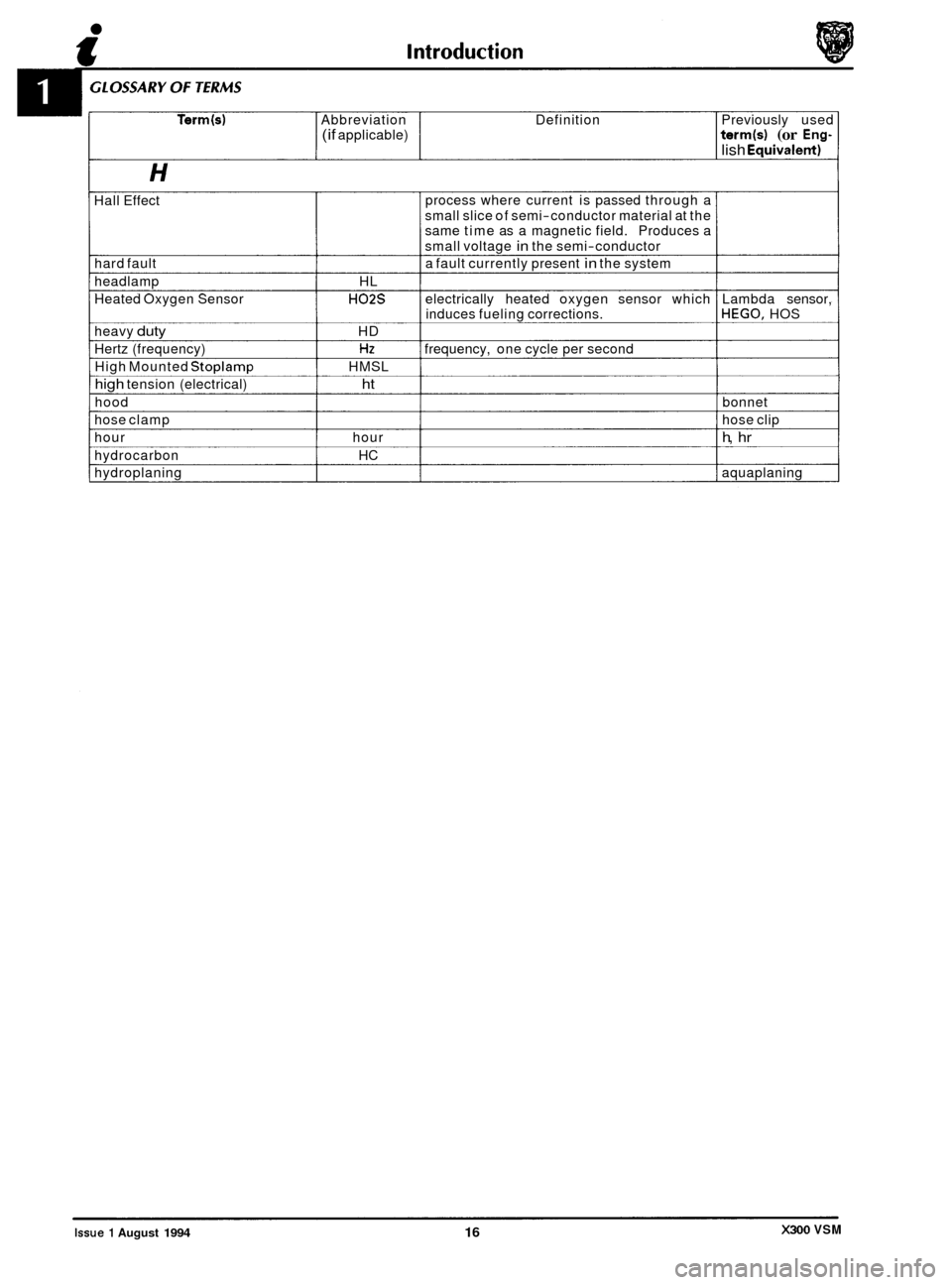
Terrn(s) Abbreviation Definition Previously used (if applicable) terrn(s1 (or Eng-
lish Eauivalent)
Hall Effect process
where current is passed through a
small slice of semi-conductor material at the
same time as a magnetic field. Produces a
small voltage
in the semi-conductor
a fault currently present
in the system
hard fault
headlamp HL
Heated Oxygen Sensor
H02S electrically heated oxygen sensor which Lambda sensor, .- induces fueling corrections. HEGO, HOS
heavy
duty HD
Hertz (frequency)
HZ frequency, one cycle per second
High Mounted
Stoplamp HMSL
high tension (electrical) ht
hood bonnet
hose clamp hose clip
hour hour
h, hr
hydrocarbon HC
hydroplaning
I aquaplaning
X300 VSM Issue 1 August 1994 16
Page 97 of 521

Fuel, Emission Control & Engine Management (V12)
5.2.4 PURGE CONTROL VALVE, RENEW
SRO 17.15.42 'A' BANK
SRO 17.15.43 'B'BANK
SRO 17.15.44 VEHICLE SET
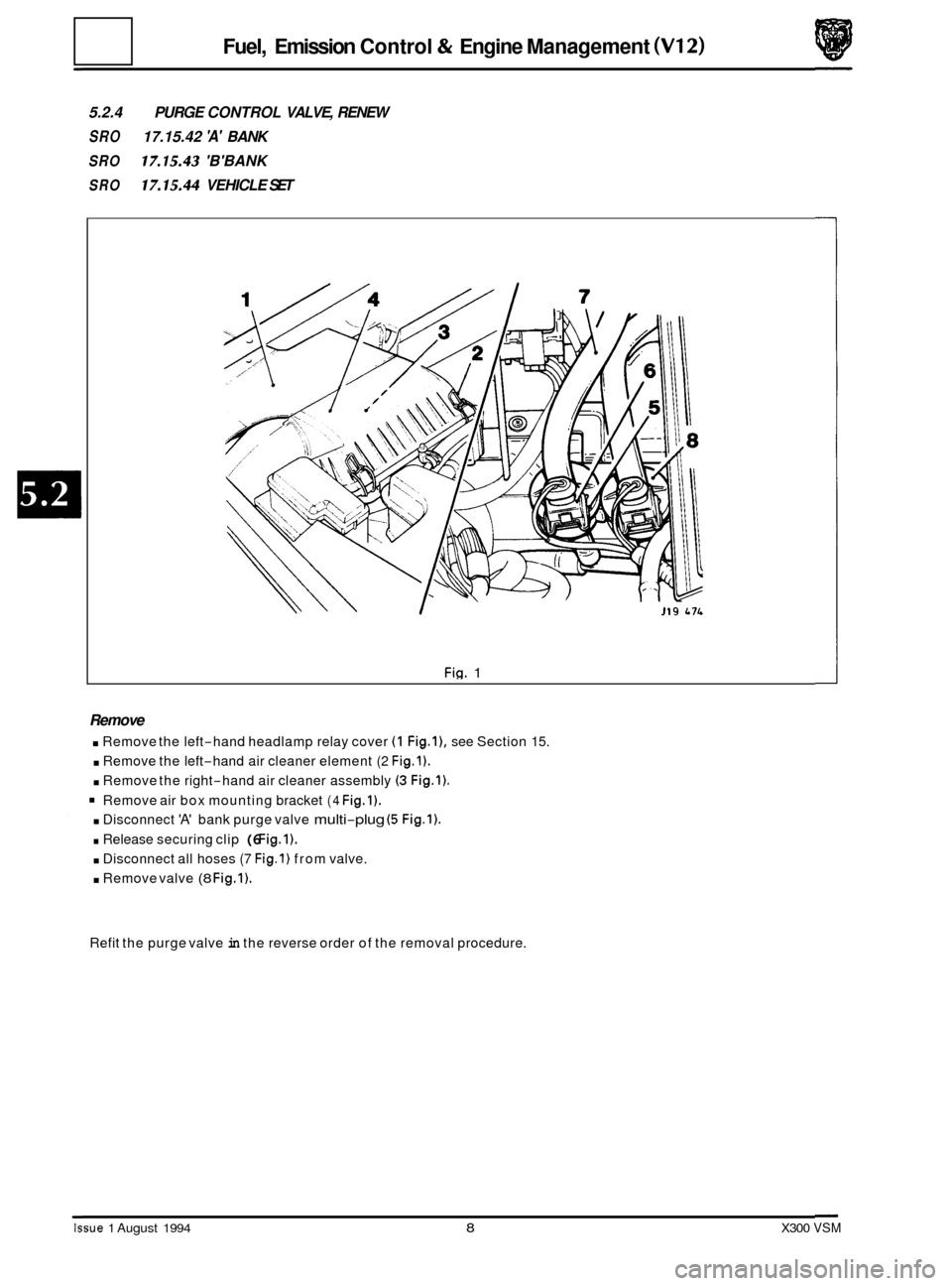
Fig. 1
Remove
. Remove the left-hand headlamp relay cover (1 Fig.l), see Section 15.
. Remove the left-hand air cleaner element (2 Fig.1).
. Remove the right-hand air cleaner assembly (3 Fig.1).
Remove air box mounting bracket (4 Fig.1).
. Disconnect 'A' bank purge valve multi-plug (5 Fig.1).
. Release securing clip (6 Fig.1).
. Disconnect all hoses (7 Fig.1) from valve.
. Remove valve (8 Fig.1).
Refit the purge valve in the reverse order of the removal procedure.
Issue 1 August 1994 8 X300 VSM
Page 297 of 521

Body Components & Trim a
13.5 HOOD
13.5.1 Hood, Description
The hood is fitted with black moulded covers over the inner fenders and behind the headlamp units; the right hand
fender cover incorporates compartments for spare fuses and tool kit (where fitted). Two gas struts attached by press- on fittings on the body and hood support the hood cover.
13.5.2 Plenum Chamber Finisher, Renew
SRO 76.10.01
9 Open the hood and fit suitable fender cover.
. Remove the wiper arm, see section 15.6.
. Undo and remove the plenum chamber finis..er securing
. Displace and reposition the plenum chamber.
. Disconnect the washer jet tubes.
9 Disconnect the washer jet multi-plugs.
. Displace the washer jet securing tangs.
. Displace and remove the washer jets (2 Fig. 1).
. Place the finisher aside.
. Fit and fully seat the washer jets to the new plenum
. Connect the washer jet multi-plugs.
9 Reconnect the washer jet tubes.
. Position the plenum chamber finisher.
. Fit and tighten the finisher securing screws.
. Refit the wiper arm.
9 Remove the fender cover and close the hood.
screws
(1 Fig. 1).
chamber
finisher.
13.5.3 Hinge, Renew
. Disconnect vehicle battery ground lead.
. Open hood and fit fender protectors.
. Remove radiator grille.
. 12 cylinder only:
. Remove fan cowl to top panel clips and move the cowl as-
sembly clear.
. Move water bleed pipe from top panel clips.
. Release fixings and remove radiator top mounting panel.
. Remove hinge securing nuts RH or LH (ground lead on the
CAUTION: Ensure that the hood cover is adequately sup- ported and that paint damage cannot occur.
. Remove hinge bolts RH or LH, noting the position of the
ground lead on the left hand side.
. To refit, carry out reversal of the above procedure, ensur- ing that the hood should be fully aligned before finally
torque tightening the fixings.
left
hand side).
I
0
Fig. 1
X300 VSM Issue 1 August 1994 42
Page 339 of 521

rl Electrical
SECTION CONTENTS
Sub-section Title SRO Page
15.6 .............
15.6.1 ............
15.6.2 ............
15.6.2.1 ..........
15.6.2.2 ..........
15.6.2.3 ..........
15.7 .............
15.8 .............
15.9 .............
15.9.1 ............
15.9.2 ............
15.10 ............
15.10.1 ..........
15.10.2 ..........
15.10.3 ..........
15.10.4 ..........
15.11 ............
15.11.1 ...........
15.12 ............
15.12.1 ..........
15.12.2 ..........
15.12.3 ..........
15.13 ............
15.13.1 ..........
Power Wash & Screen Wash / Wipe .................................................... 16
Windscreen Wipers and Washers. General Description .................................... 16
Windscreen Wipers and Washers. Switch ............................................... 16
Windscreen Wipers and Washers. Single Wipe Operation ................................. 16
Windscreen Wipers and Washers. Programmed Wash / Wipe Operation ..................... 77
Windscreen Wipers and Washers. Headlamp Power Wash Operation ....................... 17
Closures Switching .................................................................. 18
In-Car Entertainment ................................................................ 19
Lamps & Lighting Logic .............................................................. 20
Lamps & Lighting Logic. Exterior Lighting. General Description ............................ 20
Lamps & Lighting Logic. Interior Lighting. General Description ............................ 21
Harnesses &Cables ................................................................. 22
Harnesses
& Cables. Battery Power Distribution Cables. General ........................... 22
Harnesses & Cables. Main Harnesses. General Description ................................ 24
Harnesses & Cables. Link Harnesses. General Description ................................. 26
Harnesses & Cables. Harness Connectors. General Description ............................. 28
Motors and Solenoids ................................................................ 30
Motors and Solenoids. General Description ............................................. 30
Relays ........................................................................\
..... 32
Relays. Engine Compartment. General Description ....................................... 32
Relays. Passenger Compartment. General Description .................................... 34
Relays. Trunk. General Description .................................................... 36
Control Modules .................................................................... 38
Control Modules. General Description ................................................. 38
Page 357 of 521

15.6
15.6.1
The single windscreen wiper blade is controlled by a windscreen wiper/washer switch located on the right-hand side
of the steering column switchgear (see Fig.
1).
POWER WASH & SCREEN WASH/ WlPE
Windscreen Washers & Wipers, General Description
The windscreen wiper motor, part of the wiper motor
assembly operates at slow or fast speeds and drives the
lever assembly, a single arm and blade via a crank.
On
V12 engined vehicles the wiper motor assembly is
mounted to the front of the bulkhead with the motor
protruding into the plenum chamber, whilst on AJ16 engined vehicles the wiper motor assembly is mounted into
the same position, but with the motor protruding into the
engine compartment.
For wipe and wash operation
a mixture of water and special
'Jaguar Windscreen Fluid' is drawn from the PVC reservoir
assembly by
two electrically controlled pumps and is then
distributed via flexible feeder hoses interconnected using
'TEE' pieces to the screen wash jets and to heated power
wash jets (where fitted). The ends of power wash hoses are
fitted with 'quick
fit' fluid connectors.
The
two pumps, one for screen wash and one for headlamp
power wash are externally fitted to the reservoir located at
the front right
-hand side of the engine compartment.
Contained within the reservoirs pull-up neckis a serviceable
filter.
The screen wash jets with independently adjustable
eyeballs are mounted on the plenum chamber finisher and
the temperature of the fluid passing through the jets is
controlled from an ambient temperature sensor fitted near
the inlet of the right
-hand side air duct. Fig.
1
The
fluid temperature for each of the headlamp wipe wash operation is controlled by self regulating, heated power
wash jets mounted on to either side of the bumper.
Each powerwash jet is protected by
a cover supplied with an integral cover-to-bumperseal. The cover snap fixes into
the bumper.
15.6.2
This switch only operates with the ignition switch in position '11' and has the following functions:
windscreen Wiper and Washer Switch
Position 0 The wind screen wiper is switched 'OFF' and parked.
Position 1: Normal speed wiper operation is obtained by pushing the switch lever up one position.
Position 2: High speed wiper operation is obtained by pushing the switch lever fully up.
Position D: To obtain intermittent wiper operation the switch lever is pushed down and released.
The delay period will vary with vehicle speed. To cancel the function repeat the procedure.
15.6.2.1 Single Wipe Operation
To obtain a single sweep of the wiper blade, the lever is pulled towards the steering wheel and released.
W The intermittenmick wipe operations are both at slow speed and they are controlled by a Central Control
Module (CCM), which also controls the headlamp power wash operation.
Issue 1 August 1994 X300 VSM
Page 358 of 521

15.6.2.2 Programmed Wash / Wipe Operation
The end of the switch lever must be pressed inwards for the windscreen wash and wipe operation. Wash / wipe con- tinues for as long as the lever is pressed.
When released, the windscreen wiper stops immediately and the wiper blades sweep for
a further three wipes.
On pressing the end of the switch lever inward and then releasing
it, the windscreen washers operate for approximately
two seconds before stopping, whilst the wiper blade continues for a further three wipes.
N&: If the end of the switch lever is pressed while the washer fluid warning light is illuminated, the windscreen
washers, but not the wiper blade continues to operate.
0
15.6.2.3 Headlamp Power Wash Operation (where fitfed)
The headlamp power wash operates only when the programmed washer/ wipe function is selected and the side lights
are 'ON'
The headlamp power wash does not operate if the windscreen washer reservoir fluid lever is low. This is indicated
by the washer fluid level warning light illuminating.
&&: The headlamp power wash only operates on the 1st and every 6th succeeding cycle of the programme wash /wipe switch, after the ignition switch has been turned to position '11'.
X300 VSM 17 Issue 1 August 1994
Page 361 of 521

rl Electrical
15.9 LAMPS & LIGHTING LOGIC
15.9.1 Exterior Lighting, General Description
1
I t
4
1.1
a ;7 10
11 12 13 14 15 22
J86-1713
Fig. 1 Exterior Lighting
Figure
1 indicates all exterior lamps located at the front, the sides and the rear of the vehicle.
The exterior lamps consisting of
two headlamp assemblies containing the inboard and outboard headlamp units incor- porating the pilot bulbs, the fog lamps, the front direction indicator lamps and side marker lamps fitted through the
front bumper, the repeater lamps positioned on the fenders, the number plate lamps and the rear lights incorporating
tail, stop, flasher and fog lamps.
0
0
0
Page 380 of 521

86.52.01
86.91 -83
19.75.21
86.80.24
Universal garage door opener
Security
& Locking Control Module
(SLCM)
Sunroof
Mirror memory control
Seat
/ Mirror Memory (Passenger.)
Speed control
Air conditioning
(NCCM)
Transmission control
Engine Management
BPU (Body Processor Unit)
ABS (Anti
-lock Braking System &
Traction Control (where fitted).
(ABS/TC CM)
Bulb failure
Rear
Front
I Power steering
I Column / mirror ECM
Reader exciter
Location
Roof console panel
LH side upper wheel arch, inside the
trunk below fuel filler pipe
Roof console panel.
Mounted inside driver's
& passenger's
seat.
Behind passenger knee bolster.
RH side of air conditioning unit.
Behind passenger knee bolster.
RH side footwell in front of 'A' post
behind cover.
Behind passenger knee bolster.
Engine compartment below
anti-lock
braking system modulator.
Trunk inside electrical carrier box,
Engine compartment behind each
headlamp assembly.
LH side footwell on
'A' post, behind cover.
On the side of steering column.
Around the lock barrel of steering
column.
Behind passenger knee bolster below the
airbag module.
Behind bumper, LHS of vehicle
Numb
11
13
10
9
14
2
RHD
20 LHD
1
16
RHD
(1 2&6)
7 LHD
(12&16)
6 (12&16)
19 RHD
3 LHD
18 RHD
4 RHD
12
22
& 24
17 5
8
15 RHD
23 LHD
21
X300 VSM 39 issue 1 August 1994