Page 466 of 521

Body Systems & Body Repair
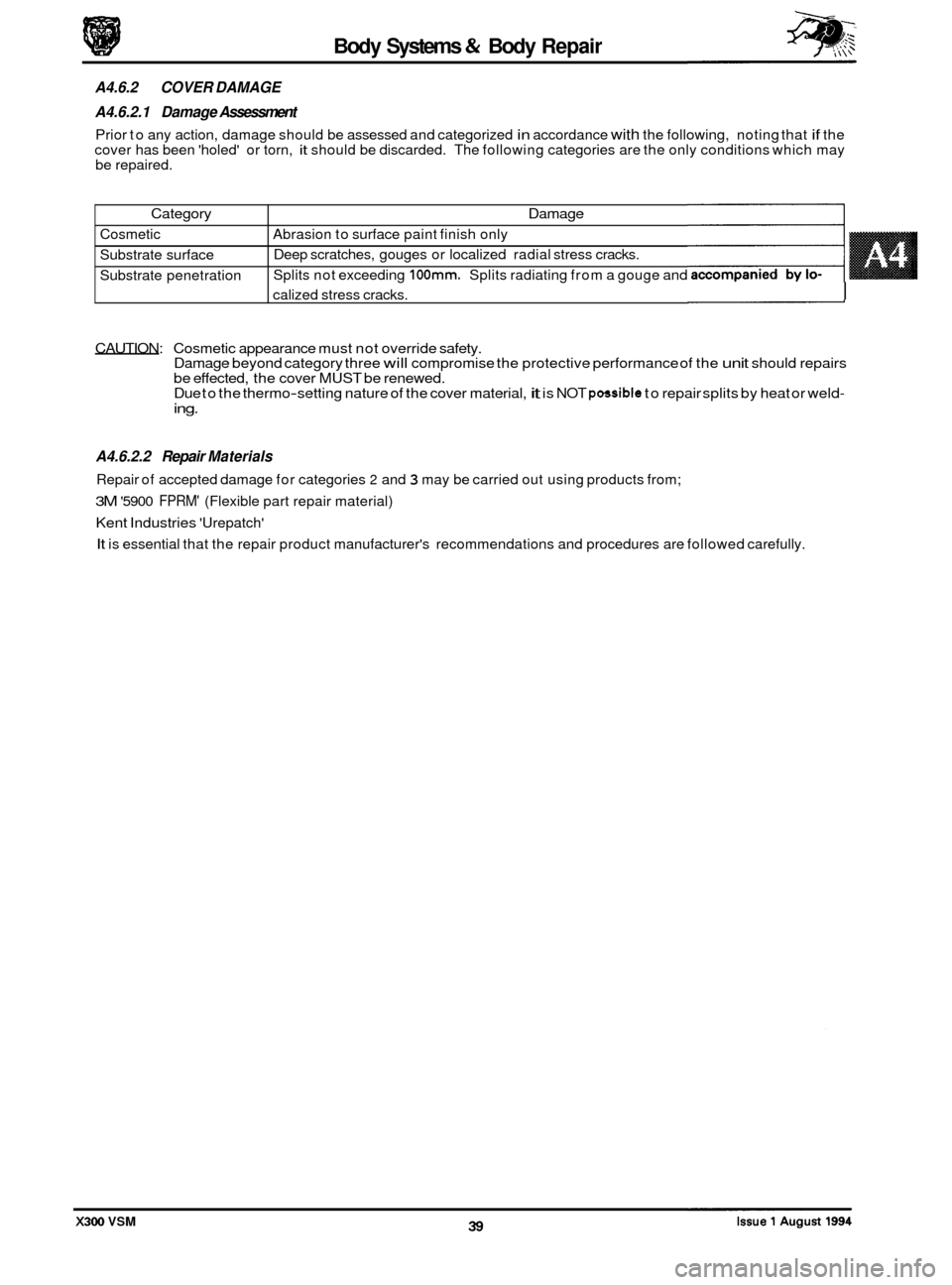
Category
Cosmetic
Substrate surface
Substrate penetration
A4.6.2 COVER DAMAGE
A4.6.2.1 Damage Assessment
Prior to any action, damage should be assessed and categorized in accordance with the following, noting that if the
cover has been 'holed' or torn, it should be discarded. The following categories are the only conditions which may
be repaired.
Damage
Abrasion to surface paint finish only
Deep scratches, gouges or localized radial stress cracks.
Splits not exceeding
100mm. Splits radiating from a gouge and
calized stress cracks.
I
CAUTION: Cosmetic appearance must not override safety.
Damage beyond category three will compromise the protective performance of the unit should repairs
be effected, the cover MUST be renewed.
Due to the thermo-setting nature of the cover material, it is NOT possible to repair splits by heat or weld- ing.
A4.6.2.2 Repair Materials
Repair of accepted damage for categories 2 and 3 may be carried out using products from;
3M '5900 FPRM' (Flexible part repair material)
Kent Industries 'Urepatch'
It is essential that the repair product manufacturer's recommendations and procedures are followed carefully.
X300 VSM
Page 467 of 521

Body Systems 4% Body Repair
A4.6.3 REFINISHING
The paint refinishing system must be approved by Jaguar Cars Ltd., and be appropriate for polyurethane substrate
application. It is important that the finishing clear lacquer includes a plasticising ingredient (mixed to the manufac-
turer's recommendation) to reflect the 'semi-flex' condition of the factory finished item.
The effect of heat decreases the cover rigidity to the point that paint
-cure temperatures require that the cover must
be supported to prevent distortion and sagging; these comments apply to 'off-car' repairs.
A4.6.3.1 Original
On an original unit where damage has been repaired, the beam will provide sufficient support for the forward part of
the unit. It is recommended that the side armatures are supported as they would be on the vehicle.
A4.6.3.2 New
Where a new cover is required, the beam may be temporarily fitted priorto painting to provide the necessary support.
A4.6.3.3 All
Asimple jig (Fig. 1)should be madeto hold the unit in thecorrect working attitude for both damage repair and refinish- ing.
CAUTION: During heat cure, the effective panel temperature must not exd 95OC.
J76-1038
Fig. 1
A4.6.4 REPLACEMENT COVERS
Replacement covers will be supplied in a primed condition and therefore must be finished in accordance with A4.6.3,
this page.
Bumper covers and replacement fixings such as bumper beam adjusters and guide blocks must be fitted and adjusted
as detailed in
A4.6.1.4 and A4.6.1.5, this section.
A4.6.5 RECYCLED
MATERIALS - GENERAL NOTE
The aluminium bumper beam, as fitted to North American specification vehicles, should not be over-looked as a com- ponent for recycling.
Side armatures will be fully assembled in replacement bumper covers, please see 'note' Recycled materials, this sec
-
tion, for important information.
Issue 1 August 1994 40
0
x300 VSM
Page 469 of 521
Body Systems & Body Repair
A4.6.7 FINISHER - DOOR FRAME
//
1. Section, door frame
2. Compression cord
3. Frame finisher
Fig.
1
+
A4.6.8 FINISHER - ROOF DRIP RAIL
2
c---
J76-1037
1. Section, roof
2. Drip rail finisher assembly
3. Assembled condition
Fig.
2
Issue 1 August 1994 42 X300 VSM