1994 JAGUAR XJ6 transmission
[x] Cancel search: transmissionPage 3 of 327
, ,
Automatic Transmission (AJ16)
SECTION CONTENTS
Sub-section Title SRO Page
8.1.1 . . . . . . . . . . . . . ZF 4HP 24 E Transmission, System Description . . . . . . . . . . . . . . . . . . . . . . . . . . . . . . . . . . . . . . . . . 1
8.1.2............. Component Descriptions ............................................................ 1
8.1.3 . . . . . . . . . . . . . Diagnostic Fault Codes . . . . . . . . . . . . . . . . . . . . . . . . . . . . . . . . . . . . . . . . . . . . . . . . . . . . . . . . . . . . . 4
8.1.4 . . . . . . . . . . . . . Fault Diagnosis . . . . . . . . . . . . . . . . . . . . . . . . . . . . . . . . . . . . . . . . . . . . . . . . . . . . . . . . . . . . . . . . . . . . 4
8.1.5.. . . . . . . . . . . . Transmission Electrical Pin Point Tests . . . . . . . . . . . . . . . . . . . . . . . . . . . . . . . . . . . . . . . . . . . . . . . . . 27
X300 EDM i Issue 1 August 1994
Page 4 of 327
Automatic Transmission (AJ16) w
8.1.1 ZF 4HP 24 E TRANSMISSION, SYSTEM DESCRIPTION
The electronic transmission system fitted to normally aspirated 4.0 liter vehicles comprises the following components:
0 ZF 4HP 24 E Automatic Transmission
0 Rotary selector switch
0 Electronic Transmission Control Module
0 Decoder Module
0 Performance Mode Switch
0 Kickdown Switch
0 Gear Selection Illumination Module
System control is effected by the transmission control module (TCM), located behind the passenger side fascia, which
continuously monitors requests made by the drivervia the gearselector, throttle pedal etc. This data is used
inconiunc- tion with the speed input from the transmission and inputs from the engine management system, to calculate optimum
shift points and control parametersfor shift pressure and ignition retardation to enhance shift quality and reduce trans-
mission unit wear.
TheTCM is also able to detect faults within the system and store the relevant fault codes for interrogation with diagnos-
tic equipment.
Gear shifts are controlled by three solenoid valves, and
a pressure control regulator, located on the valve block within
the transmission unit assembly. If a serious fault occurs, the TCM removes all electrical power from these valves and
the transmission system reverts to a mechanical default condition. This condition allows only mechanical selection
of reverse and one forward gear, either third or fourth, depending on prevailing conditions at the time of the default.
The decoder module receives inputs from the rotary switch and decodes these to drive one of six possible outputs,
illuminating the correct gear indicator on the gear selector illumination module.
The performance mode switch and kick
-down switch are used to adjust transmission operation as required by the
driver. Performance mode selection, made via a switch mounted on the gear selector mechanism surround, can be
either NORMAL, for everyday use, or SPORT, for enhanced performance. Kick
-down is activated by a switch mounted
below the accelerator pedal and is used to initiate a downward gear change, increasing torque and acceleration.
8.1.2 COMPONENT DESCRlPTIONS
Transmission Unit
The ZF 4HP 24 E automatic transmission unit houses the three solenoid valves which control gear shifts. A pressure
control valve is also located on the solenoid valve block. These four valves initiate and control shift patterns within
the transmission unit by regulating fluid flow.
Rotary Selector Switch
The seven position rotary gear selector switch is mounted on the LH side of the transmission unit and indicates gear
selection to the TCM and decoder module.
Transmission Control Module
The electronic transmission control module regulates gear changes by controlling the operation of the transmission
unit solenoid valves, and monitoring the state of other vehicle systems which have an effect on torque demand, vehicle
speed etc. The module also interfaces with the engine management system, climate control system, body processor
unit and ABS
I traction control system.
Connections from the TCM are listed on the following page.
X300 EDM 1 Issue 1 August 1994
Page 5 of 327
Automatic Transmission (AJ16)
7
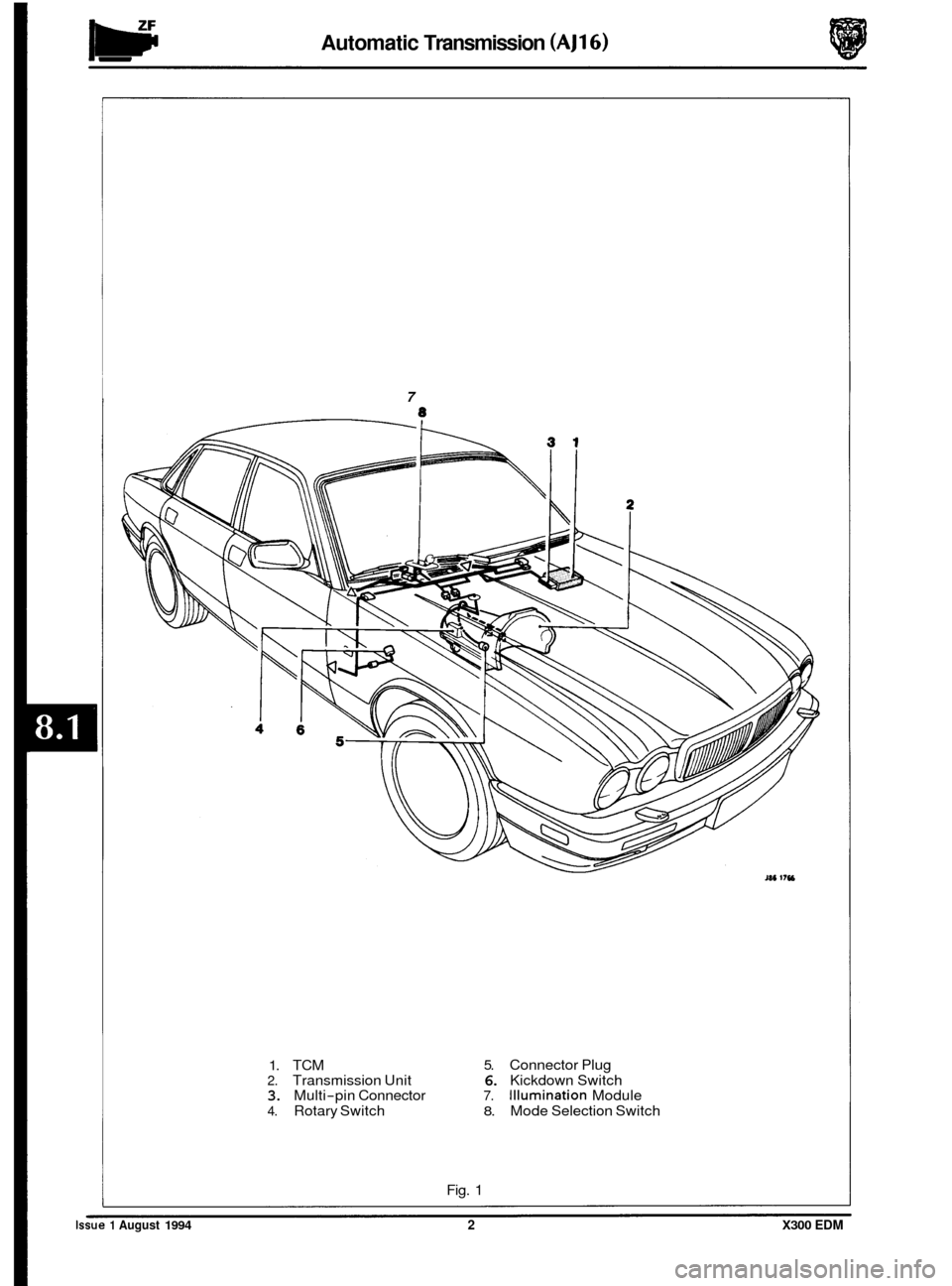
1. TCM 5. Connector Plug
2. Transmission Unit 6. Kickdown Switch 3. Multi-pin Connector 7. Illumination Module
4. Rotary Switch 8. Mode Selection Switch
Fig.
1
Issue 1 August 1994 2 X300 EDM
Page 7 of 327

Automatic Transmission (AJ16)
8.1.3 DIAGNOSTIC FAULT CODES
The following codes are stored within the TCM whenever a fault is detected on the system. The codes can be accessed
using Jaguar Diagnostic Equipment or a hand held, proprietary scan tool.
Code Description
MIL Indication Page No.
P 0603 Internal control module memory error MIL on 26
P 0605 Internal control module ROM test error
MIL on 26 I P 0702 Transmission control system electrical MIL on 5
P 0705 Transmission range sensor circuit malfunction MIL on 6
P 0706 Transmission range sensor circuit range / performance MIL on 6
8
8
P 0712 Transmission fluid temperature sensor low input -
P 0713 Transmission fluid temperature sensor high input -
P 0721 Output speed sensor circuit range / performance MIL on 10
P 0722 Output speed sensor circuit no signal MIL on 10
P 0726 MIL on 12
P 0727 1 Engine speed input circuit no signal MIL on 12
P 0743 Torque converter clutch system electrical MIL on 14
P 0748 Pressure control solenoid electrical MIL on 14
' Engine speed input circuit range / performance
P 0753 Shift solenoid A electrical MIL on 14
P 0758 Shift solenoid B electrical MIL on 14
P 1608 TCM watch-dog fault MIL on 26
P 1780 Torque reduction signal malfunction - 16
P 1781 Torque signal malfunction - 16
P 1782 Traction control input electrical - 18
P 1785 Transmission fault lamp malfunction - 20
P 1790 TP signal system range / performance MIL on 21
P 1791 TP electrical signal system MIL
on 21
P 1792 Sport mode indicator - 23
P 1794 System voltage malfunction MIL on 24
P 1796 Kickdown switch system - 24
t: Codes which do not cause the MIL to illuminate cannot be read by the hand-held scan tool as they are not SA€ P- generated.
I. Transmission Control Module (TCM)
2. Transmission Unit
3. TCM Multi-pin Connector
4. Transmission Rotary Switch
5. Transmission Connector Plug
6. Engine Control Module
7. Instrument Pack
8. ABS /Traction Control Control Module
9. Kickdown Switch
Issue 1 August 1994 4 X300 EDM
Page 8 of 327

Automatic Transmission (AJ16)
8.1.4 FA U1 T DIAGNOSIS
Transmission Control System Electrical - P 0702 (Fig. 1)
This fault code is associated with the internal relay of the Transmission Control Module, (TCM). This relay provides a
means of isolating the electro-mechanical, controlling, solenoids from the supply, allowing the transmission to revert
to a mechanical default condition.
The relay and associated circuitry is tested once during initialization and whenever
a hardware reset occurs. When the
ignition is first switched on the TCM carries out an initialization routine. During this routine the processor drives the
relay
ON then tests for the supply voltage on the output via a feedback path. If the supply voltage is not seen within
a specific time then
a fault is flagged and the TCM will run in default mode and this fault code will be stored.
A set time after the relay is turned on, it is turned off and the processor then tests for the supply again. If it is still present,
then the TCM will run in default mode and this fault code will be stored.
U: The ignition supply voltage must be greater than 8V for a fault code to be stored. If this fault is permanently
flagged, the TCM should be replaced taking care to obtain the correctly programmed variant.
Possible causes:
Faulty TCM internal relay.
Effects:
. MIL illuminated.
. Transmission warning lamp illuminated.
. Maximum fluid pressure applied.
Limp home mode applied.
. RenewTCM.
Remedy:
Fig. 1
X300 EDM 5 Issue 1 August 1994
Page 9 of 327

w Automatic Transmission (AJ16)
TRANSMISSION RANGE SENSOR - P 0705 / P 0706
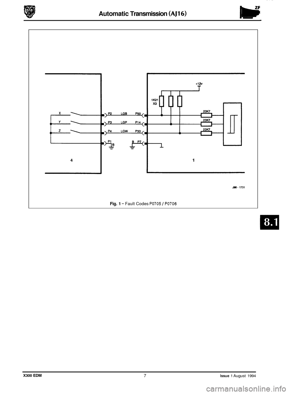
The rotary switch is located on the LH side of the transmission. The harness incorporates the transmission wiring and
runs into the car through the a hole in the LH side of the tunnel. The connectors GBOOI and GB002 are located on the
side of the selector mechanism ‘J’ gate assembly.
TRANSMISSION RANGE SENSOR CIRCUIT - P 0705
This test is performed continuously by the background diagnostics during operation. The test is a plausibility check
on the 3 bit Gray code. The test criteria is that an invalid code must not be seen. If a Z code is seen for more than looms,
then this fault code will be stored and the transmission will adopt the default function.
TRANSMISSION RANGE SENSOR CIRCUIT RANGE/ PERFORMANCE - P 0706
This is a plausibilitycheck on the 3 bit Gray code which is only performed once during cranking when the engine speed
reaches
a specific threshold. If the gear is not P or N when this test is performed, then this fault code will be flagged
and the transmission will adopt the default function.
ROTARY SWITCH
(GB002)
PIN 1 -SWITCH COMMON
PIN
2 -CODE X OUTPUT
PIN
3 -CODE Y OUTPUT
PIN
4 -CODE Z OUTPUT
Possible causes
Open circuit on X, Y or Z line from rotary switch.
9 Faulty operation of rotary switch.
Effects:
. MIL illuminated.
. Transmission warning lamp illuminated.
. Maximum fluid pressure applied.
. Limp home mode applied.
Remedy:
. Repair or renew harness I connectors.
. Check selector cable and adjust or renew if necessary.
. Check rotary switch and adjust or renew if necessary.
X300 EDM Issue 1 August 1994 6
Page 10 of 327
Automatic Transmission (AJl6)
t12v
X
Y
z
4 1
J88 - 1731
Fig. 1 - Fault Codes PO705 I PO706
X300 EDM 7 Issue 1 August 1994
Page 11 of 327
IW Automatic Transmission (AJ16)
TRANSMISSION FLUID TEMPERATURE SENSOR INPUTS P 0712 / P 0713
The transmission fluid temperature sensor is a positive temperature coefficient thermistor bead, located in the internal
wiring harness of the transmission assembly and immersed in the transmission fluid in the unit sump. The wiring is
taken out through the transmission connector and runs through the rotary switch and then into the gearbox harness
to the TCM. The pin outs on the relevant parts are as follows.
TCM ROTARY SWITCH TRANSMISSION
55 WAY CONNECTOR 12 WAY MULTI-LOCK 9 PIN DEUTSCH
(CC007) (GB002) (GB003)
PIN 46 - SIGNAL PIN 8 -SIGNAL PIN D -SIGNAL
PIN
44 -GROUND PIN 9 - GROUND PIN J -GROUND
TRANSMISSION FLUID TEMPERATURE SENSOR LOW INPUT- P 0712
This input is continuously monitored during initialization and operation by the processor and is checked against spe- cific limits to be in range. If the temperature indicated by the sensor is too low then this fault code will be stored and
the processor will use a substitute value for the transmission oil temperature.
The low limit is approximately
-50" C. This fault would indicate that the output signal line (Pin 46) is probably short
circuit to ground.
TRANSMISSION FLUID TEMPERATURE SENSOR HIGH INPUT- P 0713
This input is continuously monitored during initialization and operation by the processor and is checked against spe- cific limits to be in range. If the temperature indicated by the sensor is too high then this fault code will be stored and
the processor will use a substitute value for the transmission oil temperature. The high limit is approximately 185" C.
This fault would indicate that the input signal line (Pin 46) is probably open circuit or short circuit to battery positive
voltage (+I2 nominal).
Possible causes:
. Faulty sensor.
. Faulty harness wiring or connection to sensor.
Effects:
. Substitute oil temperature adopted by TCM.
Remedy:
Renew internal harness.
. Repair or renew harness I connectors.
Issue 1 August 1994 8 X300 EDM