1994 JAGUAR XJ6 mirror
[x] Cancel search: mirrorPage 213 of 327

Electrical rl
Carry out the exit 1 entry mode procedure below under the conditions stated below:
. Key in ignition barrel
. Driver's door closed
. Auxiliary ON
. Park brake ON
. Gear selector in Park.
Exit 1 Entry Mode
1.
2.
3.
From the driver's seat, position the memory mode switch, located on the LH side of the
steering column, to auto.
Operate the seat, column and mirror switches to preferred driving position.
Note:
Remove key from ignition. Check that seat moves backwards and column tilts upwards
and away, creating maximum space for exit.
Yes: Proceed to step
4.
No:
Seat must be a minimum of 50mm from rear end stop.
Abort test and refer to Diagnostic Sub
-Routines.
4.
5.
3.
Refit key in ignition, open driver's door. Check that seat moves backwards and column tilts
upwards and away, creating maximum space for exit.
Yes: Proceed to step
5.
No:
Leave key in ignition and exit the vehicle, closing driver's door. Ensure that column and
seat return to driving position. Re-enter vehicle and ensure that column and seat move to
entry position. Close door and check that seat
/ column return to previously selected
driving positions.
Yes: Test complete.
No: Refer to Diagnostic Sub-Routines.
Abort
test and refer to Diagnostic Sub
-Routines.
Seat heaters (driver and passenger)
1.
2.
Turn ignition ON and locate heater select switch on the center console.
Operate the switch to initiate seat heating. Does the switch surround illuminate?
Yes: Proceed to step
3.
No:
Allow sufficient time for heater to take effect. Does seat heat level increase in all
designated areas?
Abort
test and refer to Diagnostic Sub
-Routines.
4.
5.
Yes: Proceed to step 4.
No:
Allow time span to exceed 12 minutes. Does switch surround light extinguish and heating
cease?
Yes: Proceed to step
5.
No:
Re-select heating, allow cycle to commence then operate switch again. Does switch
surround light extinguish and heating cease?
Yes: Test complete
No: Refer to Diagnostic Sub-Routines.
Abort
test and refer to Diagnostic Sub
-Routines.
Abort test and refer to Diagnostic Sub
-Routines.
Page 215 of 327

Electrical IT
Fault:
Possible causes:
Remedy:
Fault: Possible causes:
Remedy:
Fault:
Possible causes:
Remedy:
Fault:
Possible causes:
Remedy:
Fault:
Possible causes:
Remedy: Steering
column positional adjustment inoperative
1. No power supply.
2. Wiring harness or connector fault.
3. Switch faulty.
4. Mechanical failure.
1. 2. Examine harness and connectors between S 1 CM -
3. Renew switch.
4.
Check fuses in 'A' post base fuse boxes.
fuse,
S I C CM - joy-stick switch and SI C CM - motors.
Identify and repair mechanical faults.
Steering column positional adjustment restricted
1. Wiring harness or connector fault.
2. Motor faulty.
3. Switch faulty.
4.
1.
2. Renew faulty motor.
3. Renew faulty switch.
4.
M echa n ica I mechanism fa i I u re.
Examine harness and connectors between
S 1 C CM -
motors and SI C CM and switch.
Identify and repair mechanical faults.
Rear view mirror positional adjustment inoperative or restricted
1. No power supply.
2.
3. Motor faulty.
4. Switch faulty.
5. Mechanical mechanism failure.
1.
2.
3. Renew faulty motor.
4. Renew faulty switch.
5.
Wiring harness or connector fault.
Check fuses in
'A' post base fuse boxes.
Examine harness and connectors between
S 1 C CM -
motors and SI C CM and switch.
Identify and repair mechanical faults.
Recall / Memory set facility inoperative or incorrect
1. Wiring harness or connector fault.
2. Potentiometers out of range or faulty.
3. Switches faulty.
1. Examine harness and connectors between SCM, S I C
CM and switches.
2. PDU only to check.
3. Renew faulty switches.
Exit \Entry facility inoperative or incorrect
1. Wiring harness or connector fault.
2. Potentiometers out of range or faulty.
3. Switch faulty.
1. Examine harness and connectors between SCM, S 1 C
CM and switches.
2.. PDU only to check.
3. Renew faulty switches. ~
Issue 1 August 1994 15.4 - 18 X300 EDM
Page 227 of 327

rl E I ect r ica I
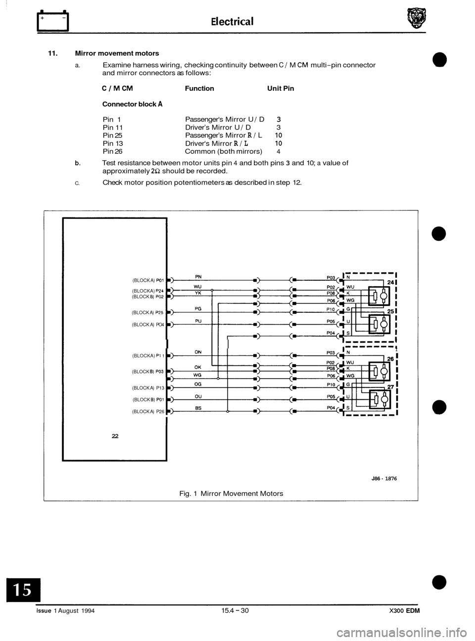
11. Mirror movement motors
a. Examine harness wiring, checking continuity between C / M CM multi-pin connector
and mirror connectors as follows:
C/MCM Function Unit Pin
Connector block
A
Pin 1
Pin 11
Pin 25
Pin 13
Pin 26 Passenger‘s
Mirror U / D 3
Driver’s Mirror U / D 3
Passenger’s Mirror
R / L 10
Driver‘s Mirror R / L 10
Common (both mirrors) 4
b. Test resistance between motor units pin 4 and both pins 3 and 10; a value of
approximately 2Q should be recorded.
Check motor position potentiometers as described in step 12.
C.
(BLOCK A) PO1
(BLOCKA) p24 (BLOCK €3) PO2
(BLOCK A) P25
(BLOCK A) PO4
(BLOCKA)
PI 1
(BLOCK B) PO3
(BLOCK A) P13
(BLOCK
6) PO1
(BLOCK A) P26
I II I I I I I I I
I
I
I
I
22
J86 - 1876
Fig. 1 Mirror Movement Motors
Issue 1 August 1994 15.4 - 30 X300 EDM
Page 228 of 327

E I ect r ica I m
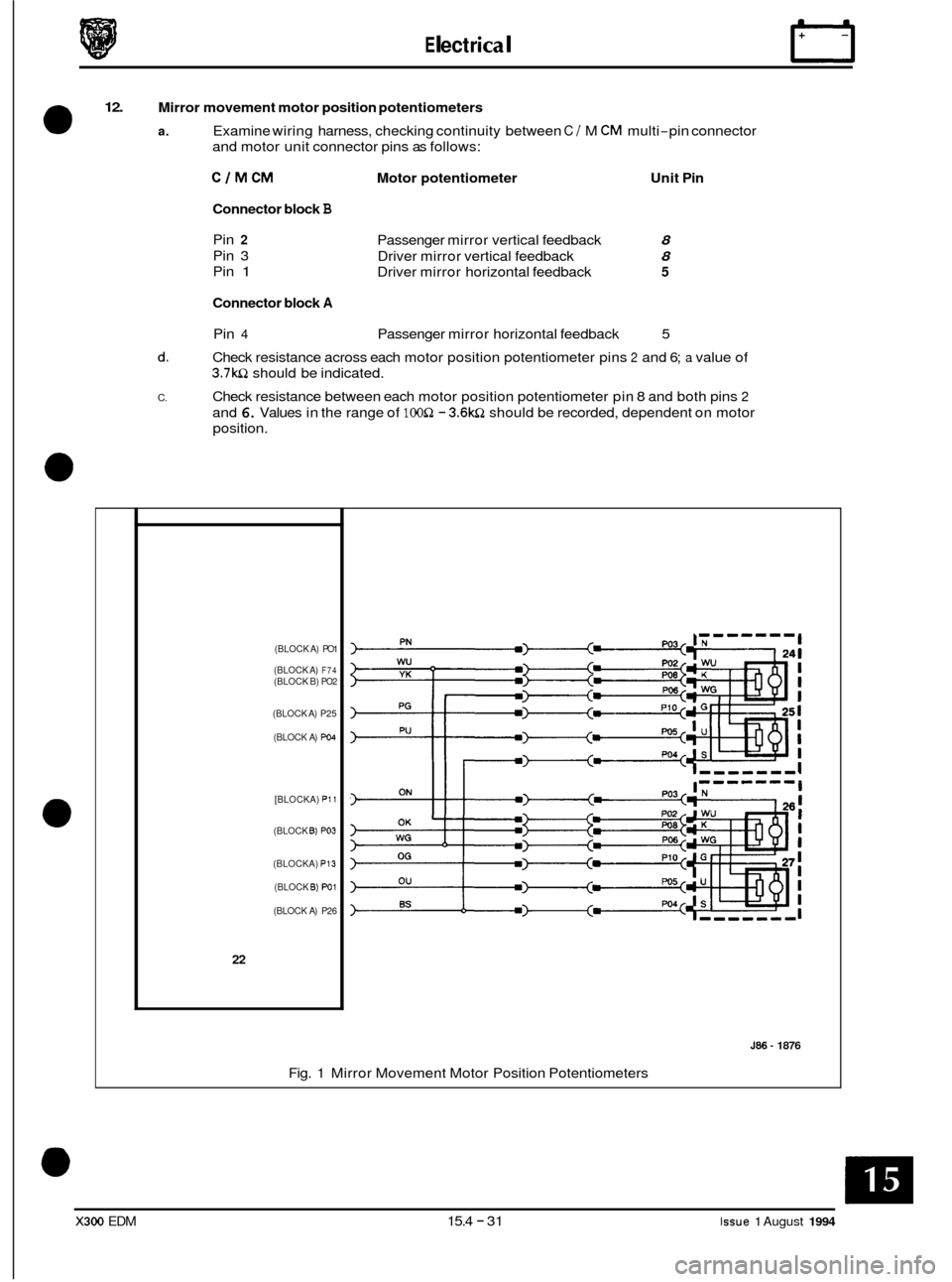
12. Mirror movement motor position potentiometers
a. Examine wiring harness, checking continuity between C / M CM multi-pin connector
and motor unit connector pins as follows:
ClMCM Motor potentiometer Unit Pin
Connector block
B
Pin 2
Pin 3
Pin
1
Connector block A
Pin 4 Passenger mirror horizontal feedback 5
d. Check resistance across each motor position potentiometer pins 2 and 6; a value of
3.7wl should be indicated.
Check resistance between each motor position potentiometer pin
8 and both pins 2
and 6. Values in the range of lOOQ - 3.6w1 should be recorded, dependent on motor
position.
C.
Passenger mirror vertical feedback
Driver mirror vertical feedback
Driver mirror horizontal feedback 8
8
5
(BLOCK A) PO1
(BLOCK A)
F74 (BLOCK B) PO2
(BLOCK A) P25
(BLOCK A)
PO4
[BLOCKA) PI1
(BLOCK B) PO3
(BLOCKA) PI3
(BLOCK B) W1
(BLOCK A) P26
22
J86 ~ 1876
Fig.
1 Mirror Movement Motor Position Potentiometers
X300 EDM 15.4 - 31 Issue 1 August 1994
Page 229 of 327

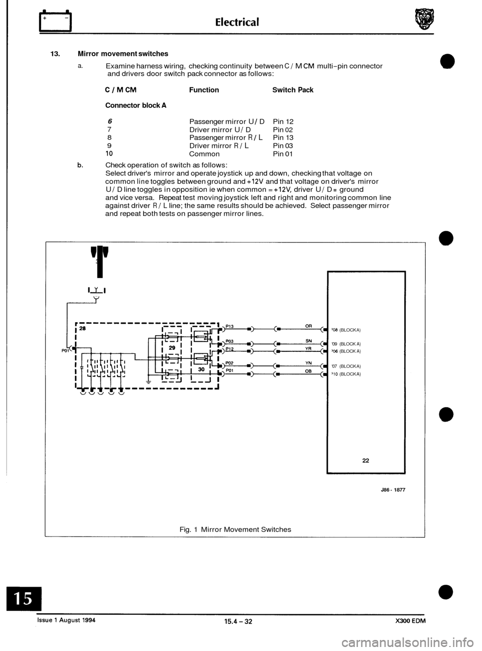
13. Mirror movement switches
a. Examine harness wiring, checking continuity between C 1 M CM multi-pin connector
and drivers door switch pack connector as follows:
CJMCM Function Switch Pack
Connector block A
6
7
8
9
10
Passenger mirror U / D Pin 12
Driver mirror
U 1 D Pin 02
Passenger mirror R / L Pin 13
Driver mirror
R 1 L Pin 03
Common Pin 01
b. Check operation of switch as follows:
Select driver's mirror and operate joystick up and down, checking that voltage on
common
line toggles between ground and +12V and that voltage on driver's mirror
U I D line toggles in opposition ie when common = +12V, driver U / D = ground
and vice versa. Repeat test moving joystick left and right and monitoring common line
against driver
R / L line; the same results should be achieved. Select passenger mirror
and repeat both tests on passenger mirror lines.
3
'I'
II v
r-
'08 (BLOCK A)
'09 (BLOCK A) 'ob (BLOCK A)
'07 (BLOCK A)
'10 (BLOCK A)
22
J86 - 1877
Fig. 1 Mirror Movement Switches
Page 232 of 327

E I ect r ica I rl
15.4.9.16 Key to schematic diagrams
I 2
I 3
i 7
, I 13
14
a1 15
j
20
p
23
30
Description
Seat control modules (driver and passenger side)
RH ,'A' post base fuse-box
LH
,'A' post base fuse-box
Head restraint motor and potentiometer
Squab recline motor and potentiometer
Seat movement motor
- fore 1 aft - and potentiometer
Seat movement motor
- rear raise 1 lower - and potentiometer
Seat movement motor
- front raise 1 lower - and potentiometer
Seat raise lower motor (manual seats)
Seat switch pack
Seat raise relay (manual seats)
Seat lower relay (manual seats)
Seat raise
/ lower selector switch (manual seats)
Lumbar pump unit
14.1 Pump
14.2 Solenoid valve
14.3 Pressure switch
Seat cushion heater
15.1 Thermostat
15.2 Inner cushion element
15.3 Outer cushion element
Squab cushion heater
Center console switch unit
17.1 Switch LED
17.2 Heatina select switch
Body processor unit
Heater relay (manual seat)
Column
tilt motor and potentiometer
Column reach motor and potentiometer
Column
I mirror control module
Column switches
23.1 Joystick
23.2 Passenger's rear view mirror up
I down motor and potentiometer
Passenger's rear view mirror left
I right motor and potentiometer
Mode switch (exit
I entry)
Driver's rear view mirror up
I down motor and potentiometer
Driver's rear view mirror left
1 right motor and potentiometer
Driver's door switch pack
Mirror polarity select switch
Mirror joystick
X300 EDM 15.4 - 35 Issue 1 August 1994
Page 233 of 327

E I ect r ica I
15.4.10 ELECTROCHROMATIC REAR VIEW MIRROR
15.4.10.1 Description
The function of the electrochromatic rearview mirror is to vary the reflectivity of the mirror glass. The mirror automati- cally varies its reflectivity to accommodate changes in traffic and light conditions to provide the driver with optimized
forward and rear vision.
The mirror contains an ambient sensor (forward facing) and
a glare sensor (rearward facing). Sensitivity control is
adjustable and at the lowest end of sensitivity control is system off. A reverse over-ride facility is incorporated; when
reverse gear is selected, the mirror operates in a high reflective state.
15.4.10.2 Test Procedure
The ambient and glare sensors and associated circuitry, the sensitivity control and reverse over-ride circuitry are all
contained within the mirror unit. Therefore only the inputs to the mirror unit can be interrogated, and if correct, the
mirror unit is defaulted.
. Measure voltage between mirror pin 1 and ground. Value should indicate battery voltage, i.e. 12V nominal.
. If an abnormally low or zero voltage is recorded, check fuse F14, RH 'A' post fuse-box, check wiring harness continu-
. Check the ground connection at the mirror unit pin 3.
Note: The mirror unit shares a common ground with the roof console and the sliding roof, therefore a fault within
the ground would effect all three systems.
. Check for 12V at mirror unit pin 2 when reverse gear selected, ignition ON; falling to OV on deselection of reverse.
/
ity between mirror unit pin 1 and fuse F14.
----- I +12VIGN ! I I I
I
L',
I I
I ,,J
F14 1. Mirror assembly
2. RH A post fuse-box
3. RearLCM
4. RH reverse lamp
5. Roof console (GND) 6. Sliding roof CM (GND)
J86-1864
Fig. 1 Electrochromatic Rear View Mirror Schematic
Issue 1 August 1994 15.4 - 36 X300 EDM