1994 JAGUAR XJ6 diagram
[x] Cancel search: diagramPage 68 of 327

I I I I I I I I
I
I
I 11 I I
I
I
I I P24 1
I
I
I
I
I I I I I I I I
I
I
I
P19: 5
P3-6
7
8
I I I I P28 I-+ 9 10
I P15t T
I
I I I
I
,t I
I
I I I I I I I I
I
I I I
1. Throttle flap actuator 2. Throttle position sensor 3. Cruise control inhibit (when traction control in operation) 4. Traction OFF / ON switch 5. Not Used 6. Gearshift inhibit (when traction control in operation) 7. Wheel speed sensors 8. Battery voltage input
9 IS0 communication BUS IO. Ignition voltage input
1 1. Speedometer signal 12 ABS MIL lamp 13. TCS MIL lamp 14. Traction control OFF lamp 15. Brake warning lamp 16. Brake fluid level switch 17. Stop lamp switch
Fig.
1 Anti-lock braking system and traction
control
-schematic diagram
0
0
Issue 1 August 1994 4 X300 EDM
Page 77 of 327

Climate Control Systems
28-
I llSA I
1.
2.
3.
4.
5.
6.
7.
8.
9.
IO.
11. 12.
13.
14.
15.
21J 20
Instrument pack
Fascia switch pack
Defrost servo.
Air distribution box Solar sensor
Control panel
Centre console
LH blower motor
Water valve
Circulation pump
Coolant temperature sensor
LH front fuse
-box
Circulation pump relay
Ambient temperature sensor
A
/ C compressor
17
16.
17.
18.
19.
20.
21.
22.
23.
24.
25.
26.
27. 28.
29.
16 1's J86 1767
Compressor clutch relay
Trinary pressure switch
Radiator fan pressure switch
Control module
RH blower motor
Engine control module
Motorized
in-car aspirator
A
/ C isolate relay
RH blower motor high speed relay RH blower motor relay
LH blower motor high speed relay
LH blower motor relay
-
-
Fig. 1 Component Location Diagram
Issue 1 August 1994 2 X300 EDM
Page 105 of 327

Electrical rl
SECTION CONTENTS
Sub-Section 15.4 Driver Ergonomics
Sub-Section Title SRO Page
15.4 ............. Driver Ergonomics .............................................................. 15.4- 1
15.4.1 ............ System Description .............................................................. 7 5.4- 1
15.4.1.1 .......... Entry/ExitMode ................................................................ 15.4-1
15.4.1.2 .......... Driving Position Set ............................................................. 15.41
15.4.1.3 .......... PassengerSeatSet ............................................................... 15.4-1
15.4.1.5 .......... Reverse Mirror Dip .............................................................. 15.4-3
15.4.2 ............ System Components ............................................................. 15.4-3
15.4.2.1 .......... Seats - Driver and Passenger ...................................................... 7 5.4-3
15.4.2.3
.......... Seat Lumbar Pump .............................................................. 15.4-3
15.4.1.4
.......... RemoteRecall .................................................................. 15.43
15.4.2.2 .......... SeatMOtors .................................................................... 15.43
15.4.2.4 .......... Seat
Heaters and Thermostats ..................................................... 15.4-3
15.4.2.5 .......... Seatswitch Pack ................................................................ 75.45
15.4.3 ............ Seat Control Module ............................................................. 15.45
15.4.3.1 .......... Seat Control Module Connector Pins ............................................... 15.4-6
15.4.4.1 .......... Column Motors ................................................................. 75.48
15.4.4.3 .......... Driver / Passenger Rear View Mirror Motors ......................................... 15.4-9
15.4.4 ............ Steering Column /Mirror ......................................................... 75.48
15.4.4.2 .......... Column Joystick Switch .......................................................... 15.48
15.4.4.4 .......... Mirror joystick .................................................................. 15.49
15.4.5 ............ Column/Mirror Control Module ................................................. 15.4-10
15.4.6 ............ Non-Memory and Manual Applications ........................................... 15.4-12
15.4.6.1 .......... Non-Memory ................................................................. 15.4-12
15.4.6.2 .......... Manualseats .................................................................. 15.4-72
15.4.6.3 .......... Manual Column ............................................................... 15.4-12
15.4.7 ............ Symptom FlowChafls .......................................................... 15.4-13
15.4.8
............ Diagnostic Sub-routines ........................................................ 15.4-17
15.4.9.16 ......... Key to Schematic Diagrams ...................................................... 15.4-35
15.4.9 ............ Pin-Point Tests ................................................................. 15.4-19
15.4.10
.......... Electrochromatic Rear View Mirror ................................................ 15.4-36
15.4.10.1 ......... Description ................................................................... 15.4-36
15.4.10.2 ......... Test Procedure ................................................................. 15.436
X300 EDM V Issue 1 August 1994
Page 155 of 327

Electrical rl
JOS 1776
1. Instrument Pack 7. Powerwash Relay
2. Body Processor Unit
(BPU) 8. Washer Fluid Level Sensor
3. Oil Pressure Sensor 9. Brake Fluid Level Sensor
4. Coolant Level Sensor 10. Ignition Switch 5. Coolant Temperature Sensor 11. Column Switch
6. Coolant Recirculation Pump Relay 12. Fuel Tank Level Sensor
Fig. 1 Component Location Diagram
Page 162 of 327

15.2.7 FAULT DIAGNOSIS
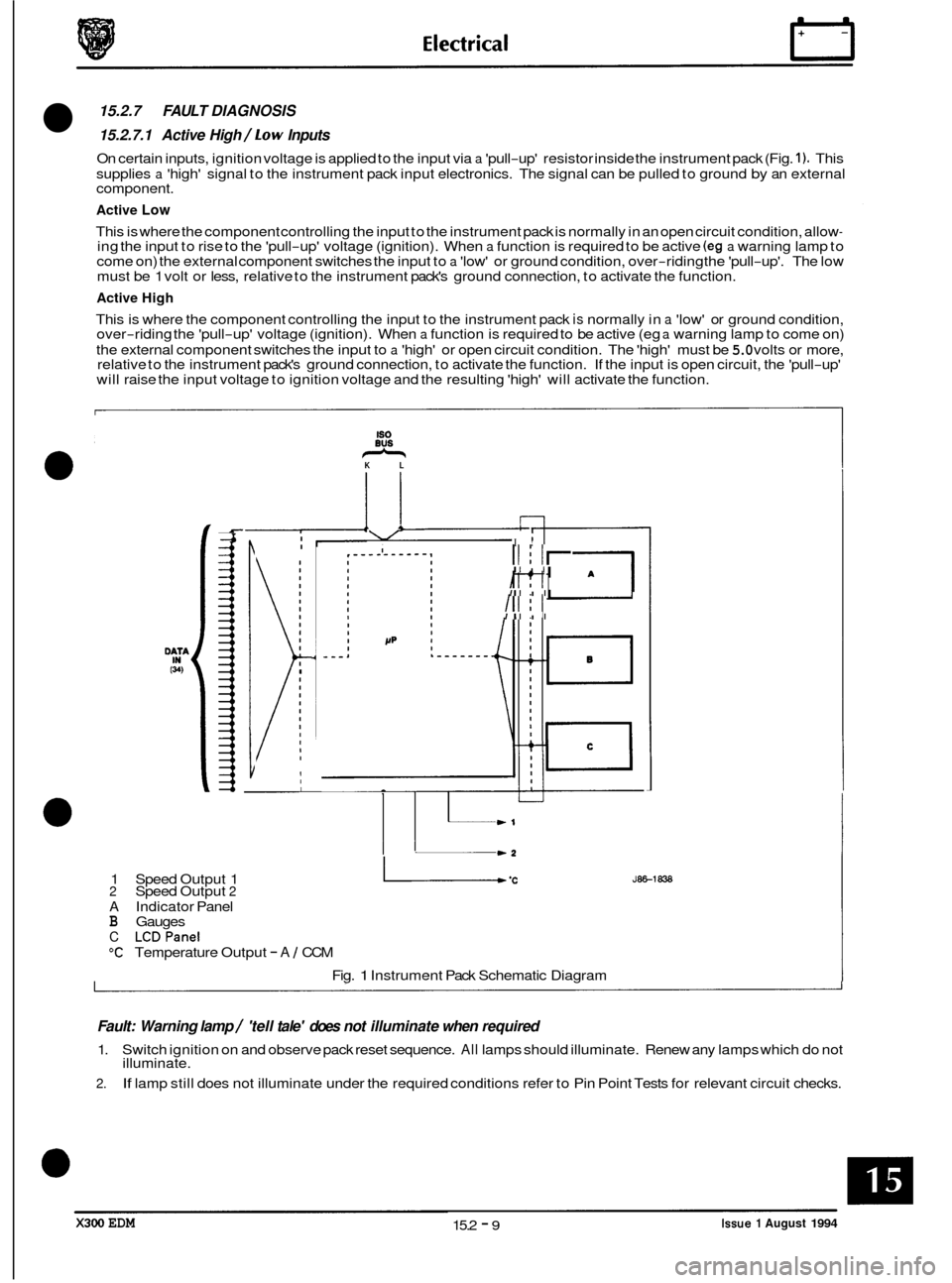
15.2.7.1 Active High /Low Inputs
On certain inputs, ignition voltage is applied to the input via a 'pull-up' resistor inside the instrument pack (Fig. 1). This
supplies
a 'high' signal to the instrument pack input electronics. The signal can be pulled to ground by an external
component.
Active Low
This is where the component controlling the input to the instrument pack is normally in an open circuit condition, allow- ing the input to rise to the 'pull-up' voltage (ignition). When a function is required to be active (eg a warning lamp to
come on) the external component switches the input to a 'low' or ground condition, over-riding the 'pull-up'. The low
must be 1 volt or less, relative to the instrument pack's ground connection, to activate the function.
Active High
This is where the component controlling the input to the instrument pack is normally in a 'low' or ground condition,
over-riding the 'pull-up' voltage (ignition). When a function is required to be active (eg a warning lamp to come on)
the external component switches the input to
a 'high' or open circuit condition. The 'high' must be 5.0 volts or more,
relative to the instrument pack's ground connection, to activate the function. If the input is open circuit, the 'pull-up'
will raise the input voltage to ignition voltage and the resulting 'high' will activate the function.
-&
60
eus KL
* \/ I I! I
I ~
I
I I
1
Ill I I '
Ill I I
I
w1
-2
1
Speed Output 1 L .C 2 Speed Output 2
A Indicator Panel B Gauges
C LCDPanel
"C Temperature Output - A 1 CCM
Fig.
1 Instrument Pack Schematic Diagram
JEE-1838
Fault: Warning lamp / 'tell tale' does not illuminate when required
1.
2.
Switch ignition on and observe pack reset sequence. All lamps should illuminate. Renew any lamps which do not
illuminate.
If lamp still does not illuminate under the required conditions refer to Pin Point Tests for relevant circuit checks.
X300 EDM Issue 1 August 1994 15.2 - 9
Page 202 of 327

E I ect r ical
15.4.2.5 Switch pack
The seat switch pack located on the side of the seat cushion houses the following switches:
Headrest; raise
/ lower
Seat cushion
-front; raise 1 lower
Seat cushion
- rear; raise 1 lower
Squab recline
/ incline
Seat assembly forward
/ backward
Lumbar pad firm
1 relax
Each switch has
a dual function and is capable of bi-directional action, so that any setting made can be reversed using
the same switch.
15.4.3 SEAT CONTROL MODULE
The Seat Control Module (SCM) is located inside the seat frame, below the cushions. The SCM controls the actions
of all position adjustment devices by monitoring switch and feedback potentiometer inputs. The SCM also provides
an interface to and from external devices with a bearing on seat operation. The module works in conjunction with the
ColumnIMirror Control Module (C/M CM) and the Securityand Locking Control Module (S/LCM) to provide positional adjustment memory functions as described previously.
There are four connectors to the SCM, designated
AI, A2, B1 and B2, which connect the various inputs 1 outputs and
peripheral devices to the module. Connections are as listed in subsection 15.4.3.1.
A1A2 B1B2
1 1 1
i 11
1 I
6
I
1' ~
1 7i 1 I 1 122
J86 1903 12 22 12 12 7 12
Fig. 1 SCM
Pin Location Diagram
X300 EDM 15.4 - 5 Issue 1 August 1994
Page 208 of 327

0
I I- - I 13 l-
BLOCK B (W-WAY, GREY) continued
' 7 Tiltawayonsignal Input Switched to ground
8 Gear selector not in park Input Switched to ground
9 Park brake ON signal Input
Switched to ground
10 Driver's door open signal Input Switched to ground
11 Remote call active Input
Switched to ground
12 Brake pedal ON signal Input
Switched to ground
I I 16 1- - -
Pin No.
1
2
3
4
Description I In/ out Signal
Power battery i Input 12v
Power ground Input ov
- - -
JDS
L I/O Serial Data
5 IJDSK I/O
13
I I
Serial Data
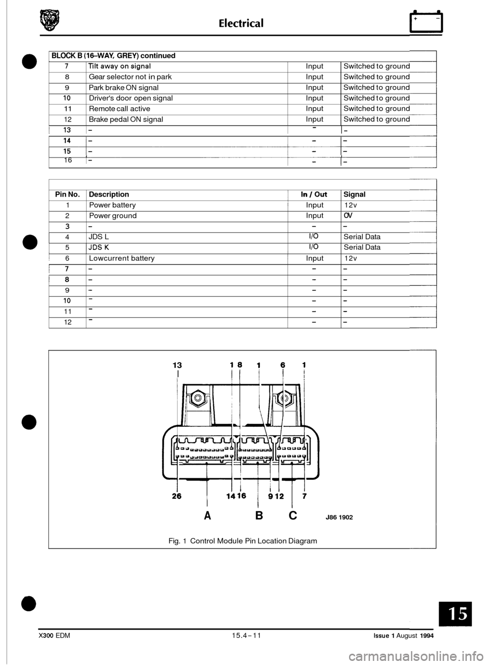
A B C J86 1902
I j 6
i7
'8
9
10
11
12
Fig. 1 Control Module Pin Location Diagram
I Lowcurrent battery ~ Input 12v
- - -
- - -
- - -
- - -
- - -
- - -
X300 EDM 15.4-11 Issue 1 August 1994
Page 216 of 327

15.4.9 PIN-POINT TESTS
The following tests give detailed information on component fault diagnosis. Refer to sub-section 15.4.9.16 for key to
schematic diagrams.
1. Seat power supply
a.
b.
Check fuses F3, F4, F9 and F12 in RH and fuse F6 in LH 'A' post base fuse boxes are
intact.
If blown determine reason for failure and renew.
Unplug harness connector from SCM and check for battery supply voltage to ground,
at pins 4,6,7 & 12 (B1 connector) and pin 11 (82 connector) with ignition on. If supply
is not recorded on all pins switch off ignition and check harness wiring continuity from
'A' post base fuse boxes to faulty lines as follows:
Connector B1
Pin 4 -fuse F 3, RH fuse box
Pin
6 -fuse F 4, RH fuse box
Pin
7 -fuse F 6, LH fuse box
Pin
12 -fuse F 9, RH fuse box
Connector 82
Pin 11 -fuse F12, RH fuse box
1 I
J86 - 1867
Fig. 1 SCM power supplies
Issue 1 August 1994 15.4 - 19 X300 EDM