1994 JAGUAR XJ6 clutch
[x] Cancel search: clutchPage 180 of 327

Electrical D ~
Ignition
+ve feed
Ignition +ve switched supply output I 01 03
06 Speed signal input
09 Traction Control input
10 Control valve control output
11 Ground
12 Ignition +ve input
14
15 ~
Stop
lamp input
17
1 Control switches input
18
j Gear select input
' Dump valve control output ~
20 I Vacuum
pump control output
15.3.2.2 Speed Control Module Pins
1 Pin No 1 Description I Comment
0
Feed to vacuum pump /control valve unit and
dump valve
via brake and clutch switches (or link)
0
0
1 10
A
11 'I n n 01 *O
I" " 1:
J86 1879
Fig. 1 Speed Control Module multi-pin Connector
15.3.2.3 Vacuum Pump /Control Valve Unit
The vacuum pump / control valve unit is located under the hood, behind the LH headlamp. When adjustment of the
throttle position is required, the pump and valve are 'pulsed' on/off by the SC CM to achieve the required vacuum and
hence vehicle speed.
15.3.2.4 Pressure Release Valve
The pressure release (or dump) valve is located adjacent to the vacuum pump /control valve module and opens, vent- ing system air pressure to atmosphere, when speed control is disabled.
X300 EDM 15.3 - 3 Issue 1 August 1994
Page 181 of 327

I3 E I ect r ical
15.3.2.5 Throttle Linkage and Bellows
The throttle linkage and bellows are located adjacent to the throttle body (below supercharger, where fitted) on 6cylin-
der vehicles, or centrally below the injector cover on 12 cylinder vehicles. The bellows expand I contract according
to the pressure drop created by the pump I control valve module, causing the linkage to act upon the throttle body,
controlling vehicle speed.
15.3.2.6
The brake and clutch pedal switches are mounted below the relevant foot pedals. Operation of a pedal, causes subse- quent switch operation, either interrupting the+12Vsupplytothe pneumaticcircuit, orsignalling tothe SC CMto disen- gage speed control, causing the dump valve to open and vent the system, returning speed control to the driver.
Brake and Clutch Pedal Switches
15.3.2.7 Speed Control Selection Switches
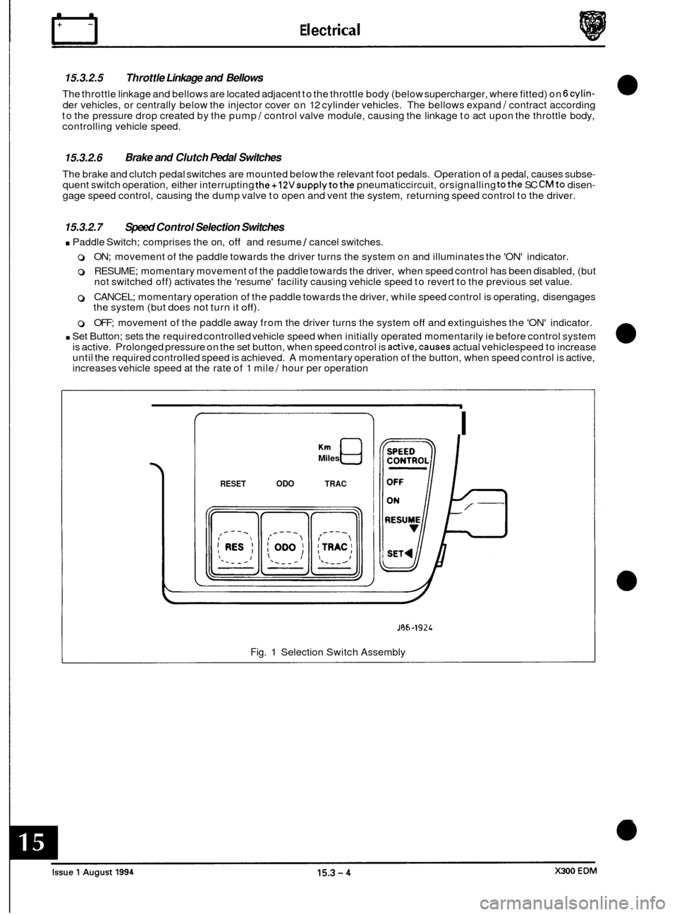
. Paddle Switch; comprises the on, off and resume 1 cancel switches.
0 ON; movement of the paddle towards the driver turns the system on and illuminates the 'ON' indicator.
0 RESUME; momentary movement of the paddle towards the driver, when speed control has been disabled, (but
not switched off) activates the 'resume' facility causing vehicle speed to revert to the previous set value.
0 CANCEL; momentary operation of the paddle towards the driver, while speed control is operating, disengages
the system (but does not turn it off).
0 OFF; movement of the paddle away from the driver turns the system off and extinguishes the 'ON' indicator.
. Set Button; sets the required controlled vehicle speed when initially operated momentarily ie before control system
is active. Prolonged pressure on the set button, when speed control is active,causes actual vehiclespeed to increase
until the required controlled speed is achieved. A momentary operation of the button, when speed control is active,
increases vehicle speed at the rate of 1 mile
/ hour per operation
Miles
RESET ODO TRAC
I
JRh-1924
Fig. 1 Selection Switch Assembly
Page 182 of 327

0 15.3.3 SYSTEM FLOW CHARTS
Systematic fault diagnosis of the speed control system cannot be accurately achieved by attempting to simulate actual
driving conditions. The system can only be reliably and safely tested using Jaguar Diagnostic Equipment.
15.3.4 DIAGNOSTIC SUB-ROUTINES
The following information details possible fault conditions, causes and remedies.
components are covered in Pin-point Tests. Detail test procedures
for
Fault: System inoperative
Possible causes:
1. Fuse FIO (LH 'A' post base fuse-box) blown.
2. Pneumatic circuit fault (ie vacuum leak)
3. Brake switch fault.
4. Clutch switch or link fault. Gear position input fault (automatic transmission only).
5. Harness wiring or connector faulty.
6. Set switch faulty.
7 Paddle switch faulty
8. Traction control input high.
9. Road speed input missing.
10 Dump valve failure.
11 Vacuum pump 1 control valve unit failure.
Remedy: 1. Examine fuse F10, if blown determine reason for failure and renew.
2. Examine all pipework, connections and components for damage or
disconnections, repair
or renew as necessary.
3. Check brake switch operation, renew if necessary.
4. Check clutch switch operation (manual transmission) or link connection I position input
(automatic transmission), renew if necessary.
5. Examine harness wiring. Examine connectors for corroded, damaged or distorted pins.
6. Check set switch operation and wiring, renew if necessary.
7. Check paddle switch operation and wiring, renew if necessary.
8. Examine harness wiring between SC CM and ABS / TC CM, check ABS /TC CM fault
diagnosis.
9. Examine harness wiring between SC CM and instrument pack, check pack fault diagnosis.
10 Renew faulty valve.
11 Renew faulty unit
0
Fault:
Cause:
1. Clutch pedal switch or harness failure.
Clutch pedal operation does not disable system
1. Remedy: Check switch operation and wiring connections. Repair or renew switch / wiring
as necessary.
Fault:
Cause:
1, Faulty signal from gear selection module.
Remedy: 1. Examine transmission fault diagnosis.
Neutral gear selection does not disable system (automatic transmissions only)
2.
2.
Harness wiring or connector fault
Examine harness between gear selection module and SC
CM pin 18.
X300 EDM 15.3 - 5 Issue 1 August 1994
Page 184 of 327

15.3.5 PIN-POINT TESTS
The following tests give detailed information on component fault diagnosis.
1. Power supply
a. Check fuse FIO in LH 'A' post base fuse-box is intact.
b. Unplug harness connector from SCCM and check for battery supply voltage to ground, at pins 1 and 2
with ignition on. If supply is not recorded on either pin switch off ignition and check harness wiring
continuity from LH
'A' post base fuse-box to splice FCS16.
If supply is recorded at pin 1 only check brake and clutch (where fitted) switch contacts (closed when
pedals not operated). For vehicles with automatic transmission ensure clutch pedal switch link is
correctly fitted. Examine harness wiring and check continuity between pin
2 and splice FCS16.
If supply is recorded at pin 2 only examine harness wiring and check continuity from pin 1 to splice
FCS
16.
c.
d.
m
P1I
1
k wv I wu I
I-------
*+12V Present Only When Ignition ON
1. Speed Control Control Module (SC CM) 7. Dump Valve
2. Clutch Switch / Link 8. Control Valve / Pump Unit
3. Brake Switch
9. Gear Position Module 4. LH 'A' Post Base Fuse-box 10. ABS Control Module 5. Switch Pack 11. Instrument Pack
6. Column Switchgear Dimmer
Fig. 1 Speed Control Power Supply
Issue 1 August 1994 X300 EDM 15.3 - 7
Page 185 of 327

n Electrical
2. Switch pack assembly
a. Unplug switch pack connector and check for battery voltage between pin 4 and ground with
ignition
off. If battery voltage is not present, switch ignition off and examine wiring harness,
checking continuity between pin
4 and splice FCS16.
b. Test operation of switches between pins as follows:
ON: Normally open; closes on operation completing circuit between pins
4 and 5 and pins 1
and 5. A resistance of less than IQ should be recorded when testing pins 4 and 5.
Minimal resistance should be recorded when testing pins 1 and 5.
SET: Normally open; closes on operation completing circuit between pins 2 and 5.
A resistance of approximately 100Q should be recorded.
RES: Normally open; closes on operation completing circuit between pins
2 and 5.
A resistance of approximately 330Q should be recorded.
c. Examine wiring harness and check continuity between pin
5 and ground.
Ptl
PI1
1
m) su
I U0
I
*+12V Present Only When Ignition ON
1. Speed Control Control Module (SC CM)
7. Dump Valve 2. Clutch Switch I Link 8. Control Valve / Pump Unit 3. Brake Switch 9. Gear Position Module
4. LH ‘A’ Post Base Fuse-box 10. ABS Control Module
5. Switch Pack 11. Instrument Pack
6. Column Switchgear Dimmer
Fig. 1 Speed Control Switches
0
0
0
0
Issue 1 August 1994 15.3 - 8 X300 EDM
Page 186 of 327

E I ect r ica I n
3. Brakeswitches
a. Unplug switch connector and check for battery voltage between pin 3 and ground with ignition
b.
on. If battery voltage is not present switch off ignition and examine harness, checking
continuity between pin 3 and splice
FCS16.
Test switch continuity across pins as follows:
Pin
3 - Pin 2; normally closed, opens on pedal operation breaking circuit continuity. Also,
checkcontinuity from pin
2 to clutch switch (where fitted) or link pin 1.
Pin 1
- Pin 4; normally open, closes on pedal operation completing circuit continuity. Also,
check continuity from switch pin 1 to
SC CM pin 15 and switch pin 4 to ground.
4. Clutch switch (where fitted) or link
a. Unplug switch connector and check for battery voltage between pin 1 and ground with ignition
on. If battery voltage is not present switch
off ignition and examine harness, checking continuity
between pin 1 and splice
FCS16.
Check continuity across switch pins 1 and 2, switch (where fitted) is normally closed and opens
on pedal operation.
Examine wiring harness, checking continuity between pin
2 and SC CM pin 12.
b.
C.
1
.---I
1. Speed Control Control Module (SC CM) 7. Dump Valve
2. Clutch Switch 1 Link 8. Control Valve / Pump Unit
3. Brake Switch 9. Gear Position Module 4. LH 'A' Post Base Fuse-box 10. ABS Control Module
5. Switch Pack 11. Instrument Pack
6. Column Switchgear Dimmer
Fig. 1 Brake and Clutch Switches
X300 EDM 15.3 - 9 Issue 1 August 1994
Page 187 of 327

rl E I ect r ica I
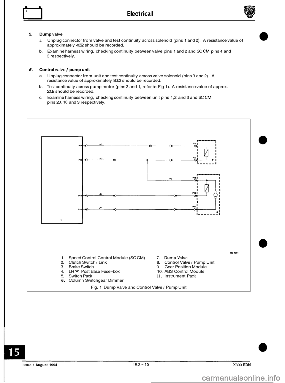
5. Dump valve
a.
b.
Unplug connector from valve and test continuity across solenoid (pins 1 and 2). A resistance value of
approximately 4052 should be recorded.
Examine harness wiring, checking continuity between valve pins 1 and
2 and SC CM pins 4 and
3 respectively.
6. Control valve / pump unit
a. Unplug connector from unit and test continuity across valve solenoid (pins 3 and 2). A
resistance value of approximately 8552 should be recorded.
b. Test continuity across pump motor (pins 3 and 1, refer to Fig 1). A resistance value of approx.
2052 should be recorded.
c. Examine harness wiring, checking continuity between unit pins 1,2 and 3 and SC
CM
pins 20, 10 and 3 respectively.
I Ii
1
1. Speed Control Control Module (SC CM) 7. Dumpvalve
2. Clutch Switch / Link 8. Control Valve / Pump Unit
3. Brake Switch 9. Gear Position Module
4. LH 'A' Post Base Fuse-box 10. ABS Control Module
5. Switch Pack
11. Instrument Pack 6. Column Switchgear Dimmer
Fig. 1 Dump Valve and Control Valve
/ Pump Unit
0
0
0
0
Issue 1 August 1994 15.3 - 10 X300 EDM
Page 188 of 327

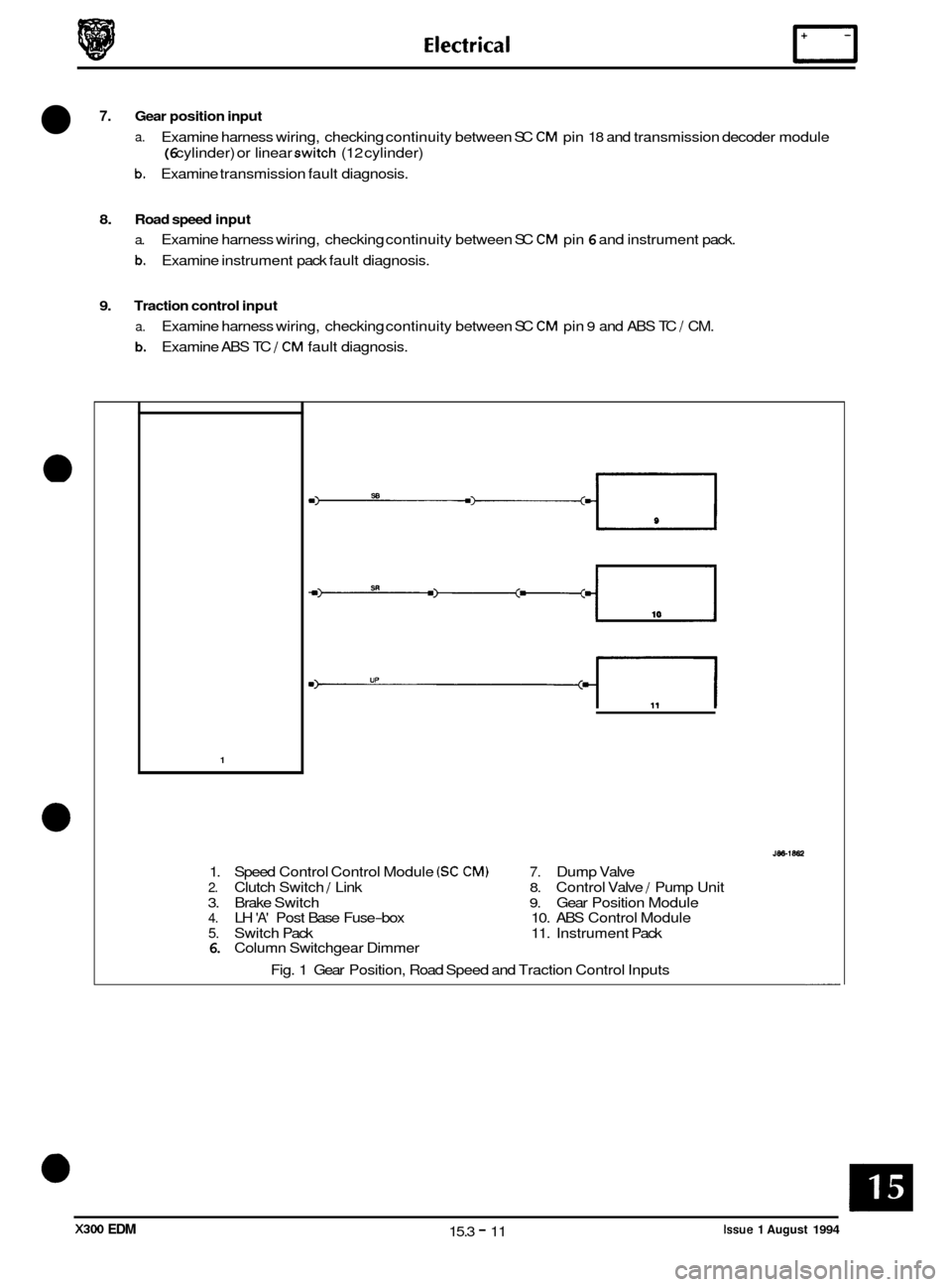
7. Gear position input
a. Examine harness wiring, checking continuity between SC CM pin 18 and transmission decoder module
(6 cylinder) or linear switch (12 cylinder)
b. Examine transmission fault diagnosis.
8. Road speed input
a. Examine harness wiring, checking continuity between SC CM pin 6 and instrument pack.
b. Examine instrument pack fault diagnosis.
9. Traction control input
a.
b.
Examine harness wiring, checking continuity between SC CM pin 9 and ABS TC J CM.
Examine ABS TC
J CM fault diagnosis.
1
1. Speed Control Control Module (SC CM) 7. Dump Valve
2. Clutch Switch J Link 8. Control Valve / Pump Unit
3. Brake Switch
9. Gear Position Module 4. LH 'A' Post Base Fuse-box 10. ABS Control Module
5. Switch Pack 11. Instrument Pack 6. Column Switchgear Dimmer
Fig. 1 Gear Position, Road Speed and Traction Control Inputs
Issue 1 August 1994 15.3 - 11 X300 EDM