1994 JAGUAR XJ6 clutch
[x] Cancel search: clutchPage 48 of 327

Powertrain Automatic Transmission (V12)
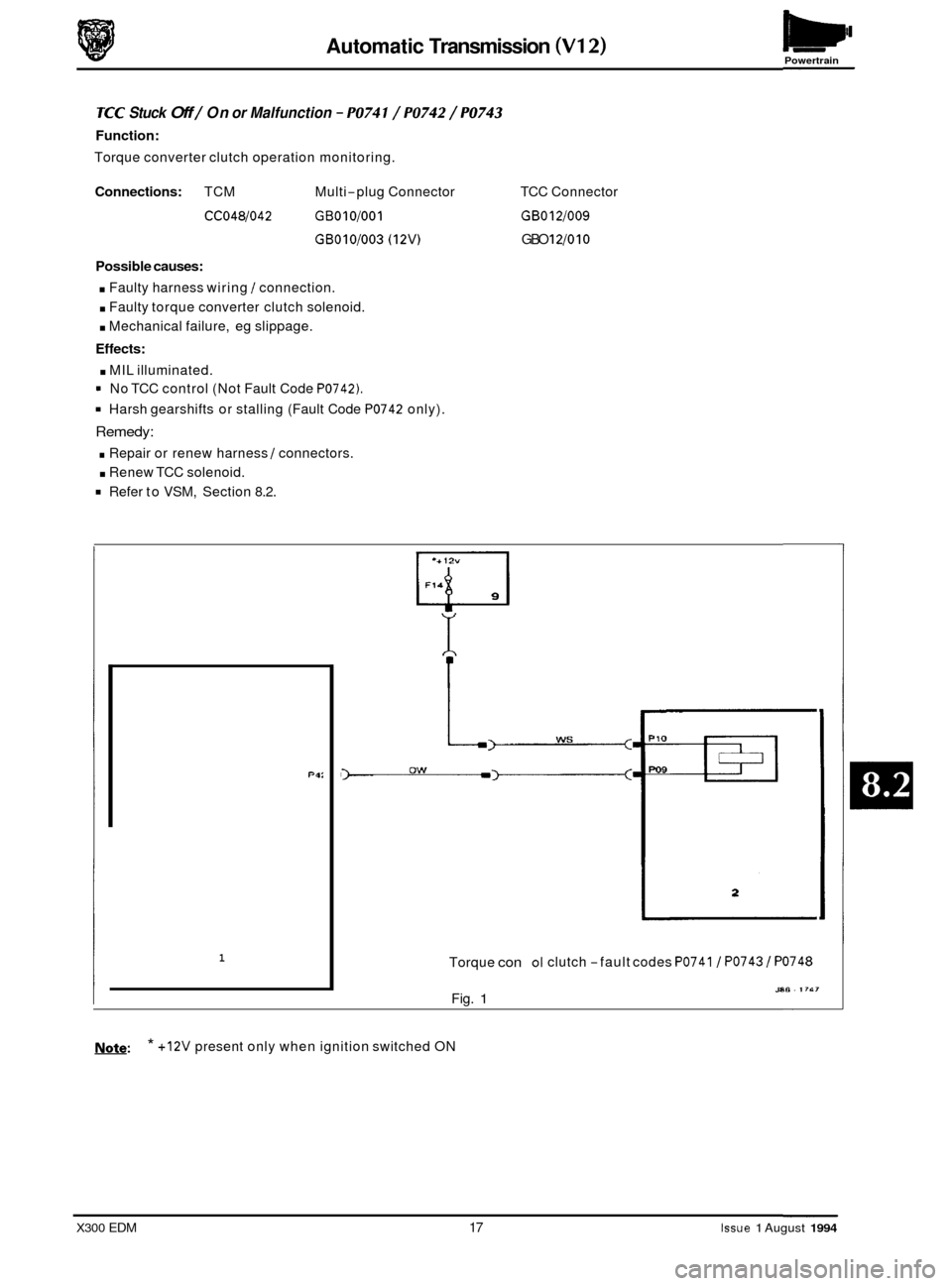
TCC Stuck Off / On or Malfunction - PO74 1 / PO742 / PO743
Function:
Torque converter clutch operation monitoring.
Connections: TCM Multi-plug Connector
CCO48/042 GBOlO/OO1
GB010/003 (12V)
Possible causes:
. Faulty harness wiring 1 connection.
. Faulty torque converter clutch solenoid.
. Mechanical failure, eg slippage.
Effects:
. MIL illuminated.
' No TCC control (Not Fault Code P0742).
Harsh gearshifts or stalling (Fault Code PO742 only).
Remedy:
. Repair or renew harness 1 connectors.
Refer to VSM, Section 8.2.
. Renew TCC solenoid. TCC
Connector
GBOl2/009
GBO 1210 10
PQ:
1 Torque con
Fig. 1
01 clutch -fault codes PO741 1 PO743 I PO748
J80 - IT47
Note: * +12V present only when ignition switched ON
X300 EDM 17 Issue 1 August 1994
Page 51 of 327

Automatic Transmission (V12) Powertrain
Shift Malfunction (Max- Adapt) - PO780
Function:
Transmission internal operation monitoring.
Possible causes:
. Mechanical wear 1 failure.
Effects:
. Harsher shifts.
Remedy:
. Refer to VSM, Section 8.2.
Transmission Component Slipping - PI 739
Function:
Transmission internal operation monitoring.
Possible causes:
Faulty harness wiring /connection.
. Fuse blown.
. Faulty torque converter clutch.
Mechanical wear.
Effects:
. MIL lamp illuminated.
. Harsh shifts.
Remedy:
. Repair or renew harness 1 connector.
Renew fuse F14 in LH heelboard fuse-box on determining reason for rupture.
Refer to VSM, Section 8.2.
0
0
Issue 1 August 1994 20 X300 EDM
Page 77 of 327

Climate Control Systems
28-
I llSA I
1.
2.
3.
4.
5.
6.
7.
8.
9.
IO.
11. 12.
13.
14.
15.
21J 20
Instrument pack
Fascia switch pack
Defrost servo.
Air distribution box Solar sensor
Control panel
Centre console
LH blower motor
Water valve
Circulation pump
Coolant temperature sensor
LH front fuse
-box
Circulation pump relay
Ambient temperature sensor
A
/ C compressor
17
16.
17.
18.
19.
20.
21.
22.
23.
24.
25.
26.
27. 28.
29.
16 1's J86 1767
Compressor clutch relay
Trinary pressure switch
Radiator fan pressure switch
Control module
RH blower motor
Engine control module
Motorized
in-car aspirator
A
/ C isolate relay
RH blower motor high speed relay RH blower motor relay
LH blower motor high speed relay
LH blower motor relay
-
-
Fig. 1 Component Location Diagram
Issue 1 August 1994 2 X300 EDM
Page 78 of 327

Climate Control Systems
System Differences
m:
Heater only vehicles do not have the following fitted:
This section applies generally to both air conditioning and heater systems. System specific descriptions, pro-
cedures, tests etc. are indicated.
0 Solar sensor
0 Clutch request and acknowledge circuitry.
0 Refrigerant pressure switch.
0 Control panel - deletion of air conditioning button.
6 cyl. engined vehicles do not have either the electrical load inhibit or the compressor lock sensor.
Heated Front Screen
(HFS) is optional on both air conditioning and heater panel versions.
14.2 COMPONENT DESCRIPTIONS
14.2.1 Control Panel
The control panel (Fig. 1) provides the operator interface with the climate control system.
The control panel communicates with the
A / CCM via a serial data communications link. During each data transfer
cycle the control panel states whether it is an air conditioning or heater version, thus enabling the A/ CCM to control
the system functions accordingly.
Tontrol panel operation is described in detail in the 'Climate Control Systems' section of the VSM.
-
Fig. 1 Control Panel (A / C with Heated front Screen)
J86 - I726
14.2.2 Control Panel Inputs /Outputs
Description I CableColor
I 1 I Output clock I Grey I
2 Output start Grey / Red
3 Input data
in Grey / Yellow
4 Output
data out Grey / Green
5 Output
ignition positive White / Red
6 Output auxiliary positive
White / Blue
7 Output
ground Black
8 Dimmer
Red
9 Dimmer override Red / Green
I 10 I Not connected I- I
I 11 I Not connected I- I
I 12 I Not connected l- I
X300 EDM 3 Issue 1 August 1994
Page 80 of 327

Climate Control Systems
14.2.8 Heater Matrix Temperature Sensor
This sensor is positioned inside the air conditioning unit just
downstream of the heater matrix. The sensor monitors the
post
-heater air temperature, before the air is distributed to
the passenger compartment. In conjunction with the A / CCM this sensor provides the input to maintain a constant
outlet temperature.
14.2.9 Coolant Temperature Signal
This input is required to provide blower inhibit control, to
avoid cold
air being delivered in heating mode when the en- gine coolant temperature is below 3OOC. The input also
monitors the temperature of the coolant delivered to the
heater matrix to assist outlet temperature control.
14.2. IO Compressor ON Signal
This signal line monitors the compressor relay to inform the
A/ CCM of the compressor status and to facilitate lock detec-
tion and error sensing.
14.2.11 Motorized In-car Aspirator (Fig. 1)
The Motorized In-car Aspirator (MIA) detects the air tem- perature within the passenger compartment. A small motor
driven fan (blown aspirator) draws air across the thermistor,
which changes its electrical resistances in response to
changes in air temperature, converting
a temperature rating
into an electrical signal.
The MIA is located on the back of the driver's side knee
bolster.
14.2.12 Compressor Lock Signal - 12 cy/. vehicles only
This signal provides the A / CCM with compressor rotation
speed. This is then compared with engine rotation speed.
If the ratio of the compressor speed against engine speed
drops belowthe A/CCM limits, indicating compressor/ belt
slippage, the compressor clutch is disengaged.
When compressor clutch disengaging commences the A/C
LED on the control panel will flash once per second.
14.2.13 Refrigerant Pressure Switch (A/C Vehicles only)
The refrigerant pressure switch (Fig. 2) is located under the
hood on the liquid line.
The switch contacts open when abnormal pressures are
sensed. This action inhibits the compressor clutch drive.
14.2.14 Water Valve
The water valve is used in conjunction with the water pump
to regulate the output air temperature. The water valve is off when the ignition is on, engine not running.
14.2.15 Water Pump
The water pump is energized in all engine running modes
except for under cold coolant condition at blower inhibit and
in panel
off mode. The water pump is off when the ignition
is on, engine not running.
If
J82-488
KI Fia. 1 I
Fia. 2
X300 EDM 5 Issue 1 August 1994
Page 104 of 327

Electrical rl
SECTION CON TENTS
Sub-Section 15.3 Speed Control
Subsection Title SRO Page
15.3 ............. SpeedControl .................................................................. 15.3-1
15.3.1
............ System Description .............................................................. 15.3-1
15.3.2.
........... Component Descriptions ......................................................... 15.3-1
15.3.2.1
.......... Electronic Control Module ........................................................ 15.3-1
15.3.2.2
.......... Speed Control Module Pins ....................................................... 15.3-3
15.3.2.3
.......... Vacuum Pump/Control Valve Unit ................................................ 75.3-3
15.3.2.4 .......... Pressure Release Valve ........................................................... 15.3-3
15.3.2.5
.......... Throttle Linkage and Bellows ..................................................... 15.34
15.3.2.6 .......... Brake and Clutch Pedal Switches .................................................. 15.3-4
15.3.2.7
.......... Speed Control Selection Switches .................................................. 15.34
15.3.3 ............ System Flowcharts .............................................................. 15.3-5
15.3.4
............ Diagnostic Subroutines ......................................................... 7 5.3-5
15.3.5
............ Pin Point Tests .................................................................. 15.3-7
X300 EDM iv Issue 1 August 1994
Page 178 of 327

E I ect r ical IT
SPEED CONTROL
System Description
0 15.3 15.3.1
The speed control system provides an automatic cruise facility, allowing a constant speed to be maintained without
accelerator pedal operation. The system comprises the following components:
0 Electronic control unit
0 Vacuum dump valve
0 Control valve
0 Vacuum pump
0 Mechanical throttle linkage and bellows
0 Selection switch
0 Brake and clutch pedal switches
On selection of speed control, via the switches mounted on the driver's side fascia, the vacuum dump valve, pump and
control valve will energize, creating
a partial vacuum in the bellows assembly. The bellows assembly acts upon the
throttle linkage to adjust throttle position, maintaining vehicle speed at the value when control is selected.
Speed control is determined by the Speed Control Control Module
(SC CM) which monitors a speed signal delivered
from the instrument pack (initially from the ABS rear LH wheel speed sensor) to determine vehicle speed.
Speedcontrol isdisabled, returning control tothedriver,
byoperationofthevacuumdumpvalve,ifanyofthefollowing situations occur: 0
0 Braking
0 Clutch operation (3.2 / 4.0 litre manual transmission vehicles only)
o Drive de-select ie P, N or R (automatic transmissions only, both electronic and hydraulic)
0 Traction control system (where fitted) in operation
0 Rapid speed reduction without braking input, ie double brake switch failure
0 Actual speed drop to 3/4 of cruise setting (eg when towing excessive loads under adverse conditions)
0 Vehicle speeds below w 25 mph
0 Ignition OFF
0 De-selection at switch controls
15.3.2 COMPONENT DESCRlPTlO NS
15.3.2.1 Electronic Control Module
The Speed Control Control Module (SC CM), located behind the fascia, adjacent to the steering column, provides sys- tem control and an interface to external input signals from the instrument pack, gear selector module, traction control
system, control switches, and foot pedal switches. The set speed value is retained in SC CM memory and continuously
compared to actual vehicle speed. Adjustments are made, as necessary, to maintain set speed by control of the vac- uum pump and control valve. Connections to the SC CM are listed in the table on page 3.
X300 EDM 15.3 - 1 Issue 1 August 1994
Page 179 of 327

Electrical rl
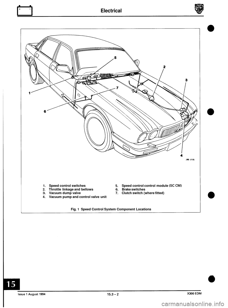
1. Speed control switches 5. Speed control control module (SC CM)
2. Throttle linkage and bellows 6. Brake switches 3. Vacuum dump valve 7. Clutch switch (where fitted)
4. Vacuum pump and control valve unit
Fig.
1 Speed Control System Component Locations