Page 65 of 73
.
Oil Filter Head Gasket, Renew
If the vehicle is fitted")
AJ16 Engine Service Manual
4.26
SRO 12.60.03
. Place a drain tray under the oil filter.
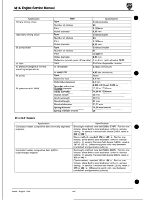
. Remove the oil filter cartridge (1 Fig. 1).
Oil Filter Head Gasket, Renew
If the vehicle is fitted with an oil cooler, remove the oil
cooler pipe clamp nut and clamp. Notethe position of and
disconnect the pipes from the oil supply housing.
. Remove and discard the '0' rings. Remove the filter head
securing bolts
(2 Fig. 1).
Remove the inner (3 Fig. 1) and outer (4 Fig. 1) housings.
. Thoroughly clean the housings, the oil cooler pipes (if fitted) and the cylinder block face.
9 Apply sealanttothe outer housing, align the inner housing
with the outer housing and fit the securing bolts to the
housing assembly. See Service Materials in the Prelimi- nary Pages. Align the assembly to the aperture in the cyl- inder block, fit and tighten the securing bolts.
If the vehicle is fitted with an oil cooler, fit new '0' rings to
the oil cooler pipes. Lubricate and connect the pipes
to the
housing.
. Fit the clamp plate and fit a new oil filter.
. Fill the engine with oil to the correct level, see Section 3.1
in the appropriate Vehicle Service Manual. Fia.
1 ~~~
Issue 1 August 1994 46
Page 66 of 73
AJ16 Engine Service Manual
@ 4.27 Oil Pan Gasket, Renew
SRO 12.60.38
Remove components as required for access and proceed as
follows.
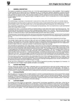
. Drain the engine oil, see Section 3.1 in the appropriate Ve-
= Remove all but two oil pan bolts (1 Fig. 1).
= Remove the bell housing to oil pan bolts.
. Remove the two remaining oil pan bolts and lower the oil
pan (2 Fig. 1).
. Clean all components and examine for damage and wear.
Renew any damaged components. Discard the oil pan
gasket.
&&: If renewing the oil pan, transfer all components to
the new oil pan.
Clean the gasket face on the cylinder block.
. Fit new oil pan gasket.
. Lift the oil pan into position, fit and torque tighten these-
hicle Service Manual.
curing bolts.
in the appropriate Vehicle Service Manual.
. Fill the engine with oil to the correct level, see Section 3.1
Replace the components removed for access.
112-83L
Fig. 1
Issue 1 August 1994 47
Page 67 of 73
AJ16 Engine Service Manual
4.28
SRO 12.60.27
Remove the oil pan, see Section 4.27.
m Place a suitable drain tray under the oil transfer housing
area and remove the transfer housing / pick-up pipe (1,2,
4,5 Fig. 1).
Oil Pump Pipe '0' Rings, Renew
. Remove the oil pump pick-up pipes (3 Fig. 1).
. Remove and discard the 'O'rings. Clean the transfer hous- ing and oil pipes.
. Carefully fit new '0' rings (lubricated with petroleum jelly)
to the oil pipes (1 Fig. 2) and refit the pipes to the oil pump.
. Fit the transfer housing to the engine. Fit and tighten the
securing bolts.
. Refit the oil pan, see Section 4.27.
Fig. 1
Fig. 2
Issue 1 August 1994 48
Page 68 of 73
AJ16 Engine Service Manual
4.29 Oil Pick-up Strainer, Renew
SRO 12.60.20
1 Remove the oil pan, see Section 4.27.
1 Remove the bolts securing the rear windage tray (1 Fig. 1) to the cylinder block and remove the tray.
1 Remove the three bolts (2 Fig. 1) securing the strainer and
remove the strainer (3 Fig. 1).
1 Clean all components and examine for damage and wear.
Apply sealant to the replacement strainer, and
fit and se- cure to the housing with the bolts. See Service Materials
in the Preliminary Pages.
1 Refittherear windagetraytothecylinder blockand secure
with the bolts.
1 Refit the oil pan, see Section 4.27.
Fig. 1
Issue 1 August 1994 49
Page 69 of 73
AJ16 Engine Service Manual
4.30
SRO 12.60.56
Remove the oil pan, see Section 4.27.
Remove oil pressure relief valve screw cap (1 Fig. 1) and
collect spring (2 Fig.
I), valve (4 Fig. I), and mandrel (3 Fig. 1).
Check the valve spring and mandrel for wear, scoring or pitting, renew if damaged.
Measure the components against the specifications listed in Service Data in the Preliminary Pages.
If any of the components are suspect, they must be re- newed.
. Lubricate and assemble the mandrel, spring and valve.
Fit and tighten the relief valve screw cap.
. Refit the oil pan, see Section 4.27.
Oil Pressure ReYief Valve AssemblB Renew
1116.1
Fig. 1
Issue 1 August 1994 50
Page 70 of 73

AJ16 Engine Service Manual
4.31 Oil Pump, Renew
SRO 12.60.26
Remove the oil pan, see Section 4.27.
1 Place a drain tray under the transfer housing. Remove the
housing bolts and housing
(1,2 Fig. 1).
. Remove the pick-up pipes (3 Fig. l), push back the lock
tabs (1 Fig. 2) and remove the pump sprocket bolts (2 Fig. 2).
. Remove the oil pump drive sprocket (3 Fig. 2), tab washer (4 Fig. 2) and shims.
. Remove the oil pump securing bolts and remove the
pump.
. Removethe pressure relief valve cap, spring, mandrel and
valve
(1-4 Fig. 3).
1 Clean the mating face in the cylinder block, the relief valve
assembly, sprocket and shims.
. Lubricate the relief valve assembly, assemble into new
pump, tighten the cap.
. Fitthe new oil pump tothe engine and tighten thesecuring
bolts.
1 Movethedrivechain asfar rearward aspossible,fit a shim
pack of 0.015 in. thickness to the oil pump flange (3 Fig. 4), align the bolt holes, fit the drive sprocket and two securing
bolts. Using
a straight edge (2 Fig. 41, check the alignment
of the oil pump drive sprocket (1 Fig. 4) and crankshaft
sprocket (4 Fig. 4).
1 Remove and refit the pump drive sprocket and adjust the
value of shim thickness as required in order to align the
sprockets.
. When the alignment is satisfactory, remove the pump
sprocket. Fit the chain and shims to the sprocket,fit to the
oil pump. Fit the tab washer and securing bolts. Tighten
the bolts and lock over the tabs.
. Ensure that the tension of the oil pump drive chain is cor- rect, see Service Data in the Preliminary Pages. Adjust by
slackening the tensioner securing screws, tapping the
tensioner inwards to increase the tension, and securing in
position when the tension is correct.
1 Fit new ‘0 rings to the oil pump pick-up pipes.
. Lubricate and refit the pipes to the pump.
1 Fit and seat the transfer housing. Fit and tighten the secur-
. Refit the oil pan, see Section 4.27.
ing bolts.
Fig. 3
Fig. 4
Issue 1 August 1994 51
Page 71 of 73
AJ16 Engine Service Manual
4.32 Oil Pump, Overhaul
SRO 12.60.32
8 Remove the oil pump, see Section 4.31.
1 Remove the bolts securing the pump body.
1 Remove the pump body, pump outer rotor, backplate se-
1 Clean all component parts of the pump.
1 Check all the clearance and components for undue wear
(Fig.
1) and (Fig. 2). Check tolerances, see Service Data in
the Preliminary Pages.
curing
bolts, the backplate and the bearing shell.
. Fit the bearing shell to the housing.
1 Apply sealantto the backplate gasketface,fitthe backplate
and securing bolts. See Service Materials in the Prelimi- nary Pages.
1 Fit the outer rotor.
a Lubricate the relief valve assembly and assemble into the
1 Tighten the relief valve cap.
1 Refit the oil pump, see Section 4.31.
pump.
Fia. 1
Fin. 2
Issue 1 August 1994 52
Page 72 of 73

D
Drive belt tensions, xvi
F
Fau It diagnosis
Diagnostic procedures, 3
Introduction, 3
Foreword, iii
General description
Construction, 1
Cooling system, 2
Crankcase breather, 1
Cylinder head, 1
Lubrication system, 1
Supercharger, 2
S
Service data, xiii
Service materials, xii
Service operations
Check & adjust
Crankshaft end
-float, 27
Valve clearances, 10
Cylinder head, 16
Engine assy., 33
Oil pump, 52
Auxiliary shaft, 44
Auxiliary shaf? rear seal, 45
Camshaft, 7
Camshaft cover gasket, 9
Connecting rod bearings, 22
Crankshaft, 24
Crankshaft damper /pulley assy., 26
Crankshaft front oil seal, 28
Crankshaft rear oil seal, 29
Cylinder head casting, 19
Cylinder head gasket, 13
Drive-plate, 31
Flywheel, 30
Main bearings, 23
Oil filter head gasket, 46
Oil pan gasket, 47
Oil pick-up strainer, 49
Oil pressure relief valve, 50
Oil pump, 51
Oil pump pipe ‘0’ ring, 48
Pistons &connecting rods, 20
Timing chain damper, 40
Timing chain tensioner
Overhaul
Renew
Lower,
42
Upper, 41
Timing chain, gear & tensioner, 37
Timing sprocket, Intermediate, 43
Transmission adapter plate, 32
Service procedures
Sealants, 2
SPS joint control system, 2
Service tools & equipment iv
T
Torque tightening specifications,
53


 to the cylinder")
 and
collect spring (2 Fig.
I), valve (4 Fig. I), a")
