Page 57 of 73
")
AJ16 Engine Service Manual
Clean all component parts and check for wear or damage,
renew worn or damaged components as necessary.
Check
forwear and renewtheauxiliaryshaft bushes (1 Fig.
1) using Service
Tool 18G 1434 (2 Fig. 1).
. Lubricate all bearing shells. Refit all shells using 18G 1434.
CAUTION: Ensure that the oil feed holes are lined up with the holes in the bearing shell (1 Fig. 2).
. Fit the timing cover blanking plate to the timing cover. Fit and tighten the securing bolts.
Lubricate and fit the auxiliary shaft to the housing.
Lubricate and fit the thrust washer.
. Refit the auxiliary shaft snap-ring.
Fit a new oil seal to the rear of the shaft.
Fit and align the oil pump drive-plate to the auxiliary shaft.
. Apply sealant to the bolt securing the driveplate, fit and
tighten the bolt. See Service Materials in the Preliminary
Pages.
Refit the power assisted steering pump, see Section 10 in
the appropriate Vehicle Service manual.
Fit the new sprocket to the crankshaft.
Using a straight edge (2 Fig. 3). check the alignment of the
oil pump drive sprocket (1 Fig. 3). and the crankshaft
sprocket (4 Fig. 3).
Push back the lock tabs from one bolt securing the oil
pump drive sprocket, and remove the bolt.
. Rotate the sprocket. Push back the locktabs from the sec- ond bolt, and remove the bolt.
m Rotate the sprocket, push back the lock tabs and remove the remaining bolt.
. Remove the tab washer and drive sprocket.
Remove the shims (3 Fig. 3). Calculate the thickness of
shim(s) required for correct sprocket alignment.
Fit and tighten a dummy stud to the oil pump drive flange. Fit and align the shims to the flange. Fit and align the
sprocket.
Fit and align the new tab washer.
Fit and tighten the first sprocket securing bolt. Do not lock
over the tab washer at this stage.
m Rotate the sprocket for access.
. Fit and tighten the second sprocket securing bolt. Lock
m Rotate the sprocket for access.
= Remove the dummy stud.
. Rotate the sprocket for access.
Re-tighten the first securing bolt.
. Re-check the sprocket alignment.
= Re-adjust as necessary.
m Lubricate the newtiming chain and position thechain over
. Lubricate the oil pump drive chain.
. Fit the drive chain to the oil pump sprocket.
* Engage the drive chain to the crank sprocket.
Ensure that the drive chain ends are on the damper side of
If the alignment is incorrect, proceed as follows:
over the
tab washer.
Fit and tighten the third
sprocket securing bolt. Lock over the tab washer.
Lock over the tab
washer.
the auxiliary drive shaft and crankshaft sprocket.
the sprockets.
Fia. 1
I I // , I,
Fia. 2
i Fig. 3
Issue 1 August 1994 38
Page 58 of 73
.
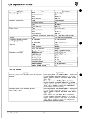
Fit and align a link plate to Service Tool JD 130 (1 Fig. 1).
Ensure that the link and tool clamp holes are aligned")
AJ16 Engine Service Manual
Fit a new linkto the drive chain (2 Fig. 1).
Fit and align a link plate to Service Tool JD 130 (1 Fig. 1).
Ensure that the link and tool clamp holes are aligned. Fit the tool /link plate assembly to the drive chain.
. Fit the ‘E’ gate (3 Fig. 1) to the tool and chain link. Ensure
that the chain is central to the tool. Tighten the tool center
bolt, fully seating the plate
on to the link.
Slacken off the tool center bolt.
. Re-position the tool clamp (4 Fig. 1) away from the chain.
Locate the link riveting head on to the
clamp. Tighten the
tool center bolt (finger tight, then further /2 to 3/4 turn).
Slacken off the tool center bolt. Remove the tightening
bar.
Re-position the clamp away from the chain.
Re-position the ‘E’ gate away from the tool / chain. Re- move the tool retaining handle and remove the tool.
Attach a dial test indicatorto the topof the engine with the
stylus resting on a piston. Rotate the engine and set No. 1 cylinder (Fig. 2) at TDC. Refit the lower static damper. Fit and tighten the securing bolts and lock over the tab
washer. Fit the oil pump chain damper in position, do not
tighten the securing bolts at this stage. Take any slack out
of the chain using hand pressure to push the damper to
- wards the center of the engine.
Tighten the bolts securing the damper.
. Lubricate the intermediate sprocket bearing.
Lift up the chain, engage the sprocket in the chain, and lo-
cate the sprocket into the bearing.
. Refit the lower tensioner assembly.
. Lubricate the upper timing chain.
. Refit the upper chain to the intermediate sprocket.
. Refit the upper static damper.
Fit and tighten the securing bolts.
Refit the upper tensioner.
. Renew the oil seal (1 Fig. 3) and refit the timing cover.
Fig. 1
-v II
Fig. 2
.12-Kl
Fig. 3
39 Issue 1 August 1994
Page 59 of 73
.
Remove the pedestal / tensioner assembly an")
AJ16 Engine Service Manual
4.20
SRO 12.65.48
Remove the timing cover.
1 Remove the upper tensioner pedestal flanged securing
bolts (3 Fig. 1).
Remove the pedestal / tensioner assembly and chain
damper
(1 Fig. 1).
Remove the tensioner pivot pin (2 Fig. 1) and remove the
tensioner from the pedestal.
. Remove the flanged bolts (5 Fig. 1) securing the upper
static damper and remove the damper (4 Fig. 1) and re-
move the damper pedestal.
1 Remove the lower timing chain tensioner securing bolts (11 Fig. 1) and remove the tensioner assembly (10, 12
Fig. 1).
1 Remove the bolts (16 Fig. 1) securing the oil pump drive
chain damper, remove the damper (17 Fig. 1).
1 Remove the flanged bolts (14 Fig. 1) securing the lower
static damper, and remove the damper
(15 Fig. 1).
Clean all component parts and checkfor wear or damage,
renew worn or damaged components as necessary.
1 Fit the oil pump chain damper in position, do not tighten
the securing bolts
at this stage. Take any slack out of the
chain using hand pressure to push the damper towards
the
center of the engine and tighten the damper securing
bolts.
Timing Chain Damper, Vehicle Set, Renew
1 Refit the lower tensioner assembly.
Refitthe upper static damper. Fit and tighten thesecuring
bolts. Refit the upper tensioner.
Renew the timing cover oil seal and refit the timing cover.
1 13 19 18 17
Fig. 1
Issue 1 August 1994 40
Page 60 of 73
4.21 Timing Chain Tensioner, Upper, Renew
SRO 12.65.29
Remove the timing cover.
Remove the upper timing chain (6 Fig. 1).
Remove the flanged bolts (3 Fig. 1) securing the tensioner
Remove the pedestal / tensioner assembly and chain
Remove the tensioner pivot pin (2 Fig. 1) and remove the
Clean the pivot pin.
Fit a new tensioner to the pedestal and fit the tensioner
pivot pin. Secure the tensioner with the flanged bolts.
Align the damper to the tensioner and fit the damper/ten- sioner assembly to the engine.
Ensure that the damper does not foul the auxiliary shaft
sprocket.
Finally tighten the securing bolts.
Fit the new timing chain.
Re-position the upper tensioner and temporarily secure to
Renew the timing cover oil seal and refit the timing cover.
pedestal.
damper
(1 Fig. 1).
tensioner from the pedestal.
the upper dampers with an elastic band. 1 13 19 18 17
Fig. 1
41 Issue 1 August 1994
Page 61 of 73
 and remove the
flanged bolts
(3 Fig. 1) securing the tensioner pedestal.")
AJ16 Engine Service Manual
4.22
SRO 12.65.30
. Remove the timing cover.
. Remove the upper timing chain (6 Fig. 1) and remove the
flanged bolts
(3 Fig. 1) securing the tensioner pedestal.
= Remove the pedestal / tensioner assembly and chain
damper (1 Fig. 1).
. Remove the tensioner pivot pin (2 Fig. 1) and remove the
tensioner from the pedestal.
. Remove the bolts (11 Fig. 1) securing the lower timing
chain tensioner, and remove the tensioner assembly (10 Fig. 1).
Timing Chain Tensioner, Lower, Renew
. Remove the lower timing chain (8 Fig. 1).
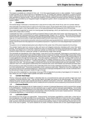
. Clean the lower tensioner assembly, remove the ball valve (1 Fig. 2) and ensure that the base of the housing (2 Fig. 2) is clean.
. Check that the ball valve is free by shaking the assembly
to ensure it rattles. If it does not, renew the valve assem- bly. If it does, renew and lubricatethe 'O'ring (3Fig. 2) and
press the valve back into the housing. The ball free move-
ment is 0,45-0,74 mm.
. Inspect the housing and the hydraulictensioner piston (4
Fig. 2) for excessive wear or scoring. Also check that the
oil hole (5 Fig. 2) is clear in the end of the piston.
. Lubricate the component parts with clean engine oil. As-
semble the tensioner by pressing and twisting the snail
clockwise until the pawl locks in the 'parK position. Fit the
tensioner assembly to the cylinder block with the guide
facing downwards.
. Fit but do not tighten the tensioner upper securing bolt,
push the guide into the housing to release the base and
align with the damper.
Align the damper with the lower bolt hole, fit and tighten
the lower bolt.
. Tighten the upper bolt, fill the tensioner oil reservoir with
oil and work the tensioner to prime with oil.
. Fit the upper tensioner to the pedestal and fit the tensioner
pivot pin, and secure with the flanged bolts
(6 Fig. 2).
m Fit the lower static damper, and secure with the flanged
bolts.
17 i3 is ii
Fig. 1
6
112 7; I
Fig. 2
42 Issue 1 August 1994
Page 62 of 73
 and remove the flanged bolts (3 Fi")
AJ16 Engine Service Manual
e 4.23 Timing Sprocket, Intermediate, Renew
SRO 12.65.26
. Remove the timing cover.
. Remove the upper timing chain (6 Fig. 1) and remove the flanged bolts (3 Fig. 1) securing the tensioner pedestal.
. Remove the pedestal / tensioner assembly and chain
damper (1 Fig. 1).
. Remove the tensioner pivot pin (2 Fig. 1) and remove the
tensioner from the pedestal.
. Remove the bolts (11 Fig. 1) securing the lower timing
chain tensioner and remove the tensioner assembly (10 Fig. 1).
. Remove the lower timing chain (8 Fig. 1).
. Remove the intermediate sprocket (9 Fig. 1).
. Examine all components (1-6 Fig. 2) for wear or damage.
. Renew worn or damaged parts as necessary.
. Fit the new intermediate sprocket.
. Fit the lower timing chain. Fit the guide assembly, valve
and '0' ring to the tensioner housing. Re-position the
chain damper for access.
. Fit the tensioner assembly to the cylinder block with the
guide facing downwards.
. Fit but do not tighten the tensioner upper securing bolt,
push the guide into the housing to release the base and
align with the damper.
Align the damper with the lower bolt hole,
fit and tighten
the lower bolt.
. Tighten the upper bolt, fill the tensioner oil reservoir with
oil and work the tensioner to prime with oil.
. Fit the upper tensioner to the pedestal and fit the tensioner
pivot pin, and secure with the flanged bolts.
. Align the damper to the tensioner and fit the damper! ten- sioner assembly to the engine.
. Tighten the securing bolts.
. Refit the upper timing chain.
. Re-position the upper tensioner and temporarily secure to
. Renew the timing cover oil seal and refit the timing cover.
the upper dampers with an elastic band.
/ 13 1s 18 ir
Fig. 1
1 L
6
J12 7II
Fig. 2
Issue 1 August 1994 43
Page 63 of 73

AJ16 Engine Service Manual
4.24 Auxiliary Shaft, Renew
SRO 12.10.30
Remove the timing cover.
. Remove the pulley woodruff key and remove the oil seal
spacer from the crankshaft.
. Remove the flanged bolts (3 Fig. 1) securing the tensioner
pedestal.
Remove the pedestal / tensioner assembly and chain
damper (1 Fig. 1).
. Remove the tensioner pivot pin (2 Fig. 1) and remove the
tensioner from the pedestal. Clean the pivot pin.
. Remove the flanged bolts (5 Fig. 1) securing the upper
static damper. Remove the damper (4 Fig. 1) and upper
timing chain (6 Fig. 1).
Remove the bolts (11 Fig. 1) securing the chain tensioner
and remove the assembly (17 Fig. 1).
Remove the power assisted steering pump assembly, see
Section 10 in the appropriate Vehicle Service manual
. Remove the pump drive coupling.
. Remove the flanged bolt (1 Fig.2) and the drive-plate (2 Fig. 2).
Using Service Tool JD 118, remove the auxiliary shaft rear
oil seal (3 Fig. 2) from its housing.
. Using right-angled snap-ring pliers remove the snap-ring (5 Fig. 2) securing the drive shaft (4 Fig.2).
. Lift the timing chain (8 Fig. 1) from the sprocket (7 Fig. 11, remove the shaft / sprocket assembly and retrieve the
thrust washer.
. Clean all component parts and checkfor wear or damage.
Renew worn or damaged parts as necessary. Clean the auxiliary bearing housing.
. Check for wear and if necessarychangethe auxiliaryshaft bushes.
. Refit the housing with new gasket. Fit and tighten the se-
curing bolts.
. Lubricate the shaft and refit the to the housing, engaging
the chain with the gear as it is fitted. Lubricate and fit the
thrust washer and secure with the snap-ring.
. Renew the auxiliary shaft rear oil seal, see Section 4.25.
. Refitthe power assisted steering pump assembly, see Sec-
. Refit the lower chain tensioner, see Section 4.22.
Refit the upper chain tensioner, see Section 4.21.
. Renew the oil seal (1 Fig. 3) and refit the timing cover.
tion
10 in
the appropriate Vehicle Service manual.
Fig. 1
Fig. 2
Fig. 3
Issue 1 August 1994 44
Page 64 of 73
AJ16 Engine Service Manual
4.25
SRO 12.10.32
Auxiliary Shaft Rear Seal, Renew
* Remove the power assisted steering pump assembly, see
Section
10 in the appropriate Vehicle Service Manual.
. Remove the pump drive coupling.
Remove the flanged bolt (1 Fig.1) and the drive-plate (2
Using ServiceTool JD 118, remove the auxiliary shaft rear
Note: Under no circumstances must the plastic insert be
removed prior to fitting the seal.
* Using ServiceTool 18G 1469fit and fully seat the auxiliary
Refit the power steering pump drive-plate and secure with
Refitthe power assisted steering pump assembly, see Sec-
Fig. 1).
oil seal (3 Fig. 1) from its housing.
shaft oil seal.
its bolt.
tion
10 in the appropriate Vehicle Service Manual.
Fig.
1
Issue 1 August 1994 45


.
Remove the flanged bolts (3 Fig. 1) securing the tensioner
Remove t")
