Page 41 of 73

AJ16 Engine Service Manual
4.8
SRO 12.17.16
Remove components as required for access and proceed as
follows.
Remove the oil pan, see Section 4.27.
. Remove the bolts securing the crankshaft windage trays
. Rotate the crankshaft for access to the first connecting rod.
Remove the nuts (1 Fig. 2) securing the connecting rod
bearing cap (2 Fig. 2) to the connecting rod and remove
the cap and bearing assembly.
Note the position of the cap relative to the connecting rod
and also that they are numbered to each other(Fig. 3). Dis- card the connecting rod bearing nuts.
CAUTION: The connecting rod bearing nuts and bolts
MUST be renewed during assembly and torque
tightened asdescribed in Section2.1, SPS Joint
Control
System.
. Discard the bearing shell (3 Fig. 31, move the connecting
rod and piston up the bore and remove the bearing shell
from the connecting rod
(2 Fig. 3).
9 Remove the 'paired' bearing caps, 1-6,2-5,3-4. as in the
previous description.
9 Clean and polish the crankshaft journals, oil the new bear- ings and fit the two halves to the connecting rods.
Ensure that the 'tag'
(1 Fig. 3) on the shell is fully
seated in the connecting rod.
Connecting Rod Bearing, Engine Set, Renew
(6 Fig. 1) to the cylinder block and remove the trays.
. Oil the crankshaft journals.
. Pull one piston and connecting rod assembly down the
bore and into position on its relative crankshaft journal.
Fit a bearing shell to the 'rnatched'connecting rod bearing
cap.
Ensure that the 'tag' on the shell is fully seated in the
connecting rod bearing cap, oil the shell and fit to
the
crankshaft/connecting rod assembly using new
connecting rod bearing nuts.
. Refit the oil pan, see Section 4.27.
Replace
the components removed for access. Fig.
1
Fia. 2
Fia. 3 ~~
Issue 1 August 1994 22
Page 42 of 73

AJ16 Engine Service Manual
4.9
SRO 12.21.39
Main Bearing, Engine Set, Renew
Remove components required for access and proceed as fol- lows.
1 Remove the oil pan see, see Section 4.27.
1 Remove the oil pump, see Section 4.31.
* Remove the windage trays securing bolts and remove the
1 Remove the bolts securing one of the main bearing caps
1 Remove and discard the bearing shell from the cap and
1 Clean the cylinder block and crankshaft.
1 Polish the crankshaft journal and liberally coat with oil.
1 Feed the new bearing shell into the cylinder block and en- sure that the tag is fully seated in its location.
1 Fit the other new bearing shell to the bearing cap. Oil the
bearing and fit the cap assembly to the cylinder block.
1 Fit and torque tighten the securing bolts.
CAUTION: The main bearing securing bolts MUST be re
- newed during assembly and torque tightened
as described
in Section 2.1, SPS Joint Control
System.
Note: Ensurethatthe bearing capisthecorrectway round,
with the cap numbers corresponding to the
numbers stamped on the oil pan mounting face
(1 Fig. 2).
1 Rotate the crankshaft to ensure that it is not being
‘pinched’ and will rotate freely.
1 Repeat the procedure for the remaining six caps and
shells.
1 Mount a suitable dial gauge and check the crankshaft end- float, see Section 4.12.
1 Recheck the end-float and if satisfactory, clean the main
bearing cap and bearing and lubricate with clean engine
oil.
1 Refit the cap and bearing assembly, remove the dial gauge
and torque tighten the main bearing cap securing bolts.
CAUTION: The main bearing securing bolts MUST be re
- newed during assembly and torque tightened
as described in Section 2.1, SPS Joint Control
System.
1 Refit the windage trays to the cylinder block. Fit and
1 Refit the oil pump, see Section 4.31.
1 Refit the oil pan, see Section 4.27.
Replace the components removed for access.
windage trays
(6 Fig, 1).
to
the cylinder block and remove the cap.
cylinder block.
0
tighten the securing bolts. Fig.
1
Fig. 2
23
Issue 1 August 1994
Page 43 of 73

AJ16 Engine Service Manual
4.10 Crankshaft, Renew
SRO 12.21.33
m Remove the engine and transmission unit from the ve-
hicle, see Section 3.1 in the appropriate Vehicle Service
Manual.
Detach the transmission unit from the engine.
Fit the engine to a stand.
Remove the cylinder head, see Section 4.4.
. Remove the crankshaft damper pulley assembly, see Sec-
. Remove the oil pan , see Section 4.27.
Remove the oil pump, see Section 4.31.
. Remove the flywheel (Manual), see Section 4.15, or re-
. Remove the timing cover.
. Remove the windage trays securing bolts (1 Fig. 1) and re- move the windage trays (2 Fig. 1).
Remove the timing chains - upper and lower and the
upper and lower tensioners see Section 4.19.
. Remove theseal/crankshaft damper spacer, the woodruff
key (1 Fig. 21, the crankshaft sprockets (2 Fig. 2) and the
inner woodruff key.
tion
4.11.
move the drive
-plate (Automatic), see Section 4.16.
. Remove the rear oil seal housing, see Section 4.14.
Remove the connecting rod bearing nuts and remove the
connecting rod bearing caps in pairs
(1-6,2-5,3-4), turn- ingthecrankshaftfor accessas required. As each connect- ing rod bearing cap is removed, ensure that each
connecting rod and connecting rod bearing cap are identi- fied to each other for re-pairing during assembly.
. As each cap is removed, its relative connecting rod and
piston assembly should be pushed up the bore, enabling
the crankshaft to be rotated to remove the remaining caps.
Care should be taken not to push the piston too far up the
cylinder bore as this will release
the piston rings.
Ensuring that the main bearing caps are marked relative
to the cylinder block (1 Fig. 3), remove the main bearing
cap bolts and the bearing caps, and carefully lift out the
crankshaft.
Remove and discard the bearing shells and the thrust
washers.
. Clean the bearing caps and the cylinder block main bear- ing housings.
Fit the new bearing shell halves to the cylinder block and
lubricate with clean engine oil.
Fig. 1
!- ,1101,
Fig. 2
Fig. 3
Issue 1 August 1994 24
Page 44 of 73

AJ16 Engine Service Manual
1 Clean and polish the crankshaft journals, lubricate and
carefully assemble the crankshaft into the cylinder block,
fit the thrust washers ensuring that the steel side of the
washer is mated to the cylinder block (1 Fig. 1).
1 Rotate the crankshaft to ensure that it turns freely.
1 Fit the main bearing shells into the main bearing caps, lu- bricate and fit to the cylinder block.
1 Start the securing bolts and carefullytap the main bearing
caps to ensure they are seated to the cylinder block.
1 Rotate thecrankshaft to ensurethat it still turnsfreely, pull
down each bearing cap individuallyand torque tighten the
securing bolts.
1 Rotate the crankshaft between pulling down each bearing
cap.
1 Check and if necessary adjust the crankshaft end-float in
accordance with Section 4.12.
1 Renew the crankshaft rear oil seal, see Section 4.14.
1 Fit a new bearing shell to the connecting rod, lubricate
1 Fit a bearing shell to theconnecting rod bearing cap, lubri-
with clean engine oil and fit to the crankshaft.
cate and fit to the connecting rod.
Fit and torque tighten
1 Turn the crankshaft over ensuring that there are no 'tiaht'
the nuts.
spots, and that the crankshaft rotates freely.
-
1 Repeat this procedure for the remaining five cylinders.
WUTION: The connecting rod bearing nuts, bolts and
main bearing securing bolts MUST be renewed during assembly and torque tightened as de- scribed in Section 2.1, SPS Joint Control Sys- tem.
1 Clean and inspect for wear or damage all the timing gears,
chains, guides and tensioners.
1 Renew any suspect component.
1 Fit and seat the crankshaft sprocket woodruff key and fit the sprocket to the crankshaft.
1 Refit the timing chains - upper and lower; and the upper
and lower tensioners, see Section 4.19.
1 Fit a dial gauge to the top ofthe cylinder blockand turn the
engine over until No.1 and 6 pistons are at TDC (Fig. 2).
1 Lubricate the upper chain and fit it to the intermediate
sprocket.
0 1 Fit an elastic band to retain the upper dampers and chain.
. Lubricate the oil pump drive chain, fit the chain to the
crankshaft sprocket and lodge in the correct position.
1 Renew the timing cover oil seal and refit the timing cover.
. Lubricate and fit the oil seal distance piece. Fit and seatthe
1 Refit the oil pump, see Section 4.31.
1 Refit the flywheel (Manual), see Section 4.15, or refit the
1 Refit the oil pan, see Section 4.27.
1 Refit the crankshaft damper /pulley assembly, see Section
1 Refit the cylinder head, see Section 4.4.
1 Remove the engine from the stand and refit the trans-
1 Refit the engine/transmission unitto thevehicle, see Sec-
damper woodruff key.
drive
-plate (Automatic), see Section 4.16.
4.11.
mission unit.
tion
3.1 in the appropriate Vehicle Service Manual.. Fig.
1
Fig. 2
Issue 1 August 1994 25
Page 45 of 73
tothecrankshaft pulley")
AJ16 Engine Service Manual
4.11
SRO 12.21.09
. Remove the air conditioning compressor drive belt.
. Remove the generator drive belt.
. Fit ServiceTool 18G 1437 (1 Fig. 1)tothecrankshaft pulley
. Wedge the tool against the crossmember.
. Remove the pulley retaining bolt.
. Remove Service Tool 18G 1437 from the pulley.
. Fit Service Tool 18G 1436/A to the pulley and tighten the
securing bolts.
. Eghten the center bolt to withdraw the pulley from the
crankshaft and remove the tool.
. Remove the timing plate securing bolts and remove the
timing plate.
. Fitthetiming platetothe new pulleyandtightenthesecur-
ing bolts.
. Fit the pulley to the engine, hand tighten the securing bolt
and fit Service Tool 18G 1437.
. Wedge the tool against the front crossmember, torque
tighten the securing bolt and remove Service Tool 18G
1437.
Crankshaft Damper / Pulley Assembly, Renew
(3 Fig. 1) and tighten the securing bolts (2 Fig. 1).
. Refit the generator drive belt.
. Refit the air conditioning compressor drive belt.
.. J
J12-830
Fia. 1
Issue 1 August 1994 26
0
0
0
Page 46 of 73

AJ16 Engine Service Manual
4.12
SRO 12.21.26
Crankshaft End-float, Check and A4ust
Remove components as required for access and proceed as
follows.
Remove the oil pan, see Section 4.27.
Remove the oil pump pick-up pipes (3 Fig. I), see Section
Remove the crankshaft windage trays (6 Fig. 1).
. Mount a suitable dial gauge and position the stylus on the
crankshaft front pulley.
. Zero the gauge, and with the use of a suitable lever,
measure the crankshaft end-float (Fig. 2). For the correct
end-float, see Service Data in the Preliminary Pages.
If the end-float exceeds the tolerances, remove the center
main bearing cap, and renew the thrust washers.
&&: When refitting the thrust washers, ensure that the
bearing face (grooved) (1 Fig. 3) and not the steel
side contacts the crankshaft.
. Recheck the end-float and if satisfactory, clean the main
bearing cap and bearing, lubricate with clean engine oil
and
fit the cap assembly to the cylinder block.
4.28. 0
Fit and
torque tighten the securing bolts.
CAUTION: The main bearing securing bolts MUST be re
-
newed during assembly and torque tightened as described in Section 2.1, SPS Joint Control
System.
Ensure that the bearing cap is the correct way round
with the cap numbers corresponding to the
numbers stamped on the oil pan mounting face.
Rotate the crankshaft to ensure that it is not being
'pinched' and will rotate freely.
m Remove the dial gauge and torque tighten the main bear- ing cap. Refit the windage trays to the cylinder block and
secure with the bolts.
w:
Refit the oil pump pick-up pipes, see Section 4.28.
Refit the oil pan, see Section 4.27.
Refit the oil filler / drain back tube.
Replace the components removed for access.
0
3
Fia. 1
Fig. 2
Fig.
3
27 Issue 1 August 1994
Page 47 of 73
AJ16 Engine Service Manual
4.13
SRO 12.21.14
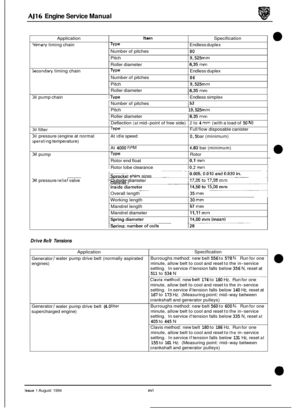
. Removethecrankshaftdamper/pulleyassembly,seeSec- tion 4.11.
- Remove the old oil seal from the timing cover using Ser-
vice Tool JD 128 (A Fig. 1).
. Fit the new oil seal (prior to fitting the crankspacer) using
Service Tool JD 129 and the crankshaft pulley bolt (B Fig.
1 ).
= Inspect the edges of the spacer for nicks, burrs and wear
marks. Renew if necessary.
. Refit the crankshaft damper/ pulley assembly, see Section 4.11.
Crankshaft Front Oil Seal, Renew
Fig. 1
Issue 1 August 1994 28
Page 48 of 73
, see Section 4.15, or the
Remove the transmission adapter securing bolts and re-
C")
AJ16 Engine Service Manual
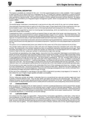
4.14 Crankshaft Rear Oil Seal, Renew
SRO 12.21.20
Remove the flywheel (Manual), see Section 4.15, or the
Remove the transmission adapter securing bolts and re-
Carefully remove the old oil seal from the adapter, clean
CAUTION: Do not remove the plastic ‘0 ring protector
from the new seal prior to fitting to the adapter.
Fit the new seal (3 Fig. 1) to the adapter and apply sealant to the appropriate faces. See Service Materials in the Pre- liminary Pages.
Locate the plastic’o’ ring protector (1 Fig. 1) on to the end of the crankshaft (2 Fig. 1).
. Push the rear seal housing (4 Fig. 1) over the crankshaft
and
up to the rear cylinder block face.
Remove the plastic ‘0’ ring protector (1 Fig. 1).
. Fit and torque tighten the transmission adapter securing
drive
-plate
(Automatic), see Section 4.16.
move the adapter.
the adapter and lubricate
the seal mounting face.
bolts.
. Refit the flywheel (Manual), see Section 4.15, or the drive- plate (Automatic), see Section 4.16.
Fin. 1
Issue 1 August 1994 29