Page 49 of 73

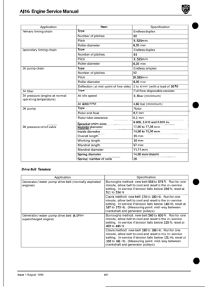
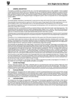
AJ16 Engine Service Manual
4.15 Engine Flywheel, Renew
SRO 12.53.07
1 Remove the transmission unit.
. Hold the flywheel in one position and remove the bolts se-
CAUTION: Make a note of the position of any balance
weights relative to the clutch cover.
Remove the balance weights. Remove the clutch assem-
curing the clutch cover to the flywheel.
bly.
WARNING: THE TWIN-MASS FLYWHEEL IS EXTREMELY HEAVY. ASSISTANCE WILL BE REQUIRED
DURING REMOVAL / REFIlTING.
Remove the eight securing bolts (1 Fig. 1) and remove the
flywheel (2 Fig. 1). Remove the needle roller race and fit
to the new flywheel.
. Fit the new flywheel to the crankshaft and tighten the se- curing bolts to the recommended torque value.
. Fit the clutch assembly to the flywheel ensuring that the
‘flywheel side’
of the drive-plate faces the flywheel. Align
the clutch with a dummy input shaft. Fit the balance
weights to the clutch cover and torque tighten the secur- ing bolts.
1 Remove the dummy shaft.
Fit the housing to the adapter plate, fit and torque tighten
the securing bolts I nuts.
1 Refit the transmission unit. Fio.
1
Issue 1 August 1994 30
Page 50 of 73
AJ16 Engine Service Manual
4.16 Engine Driveplate, Renew
SRO 12.53.13
1 Remove the transmission unit.
Remove the drive-plate securing bolts (1 Fig. 1).
Remove the drive-plate (2 Fig. 1).
. Check the crankshaft rear oil seal for leaking, renew as
Fit the new drive-plate to the crankshaft. Fit and tighten
1 Refit the transmission unit.
necessary,
see Section
4.14.
the securing bolts.
I Fin. 1
Issue 1 August 1994 31
Page 51 of 73
AJ16 Engine Service Manual
4.17 Engine Rear/ Transmission Adapter Plate, Renew
SRO 12.53.03
1 Remove the engine flywheel (Manual), see Section 4.1 5, or
the engine drive
-plate (Automatic), see Section 4.16.
Remove the lower bolt securing the starter motor and re-
position the starter motor away from the adapter plate.
1 Remove the adapter plate securing bolts and remove the
adapter plate.
* Remove the dowel pegs and blanking plugs from the
adapter plate.
m Discard the adapter plate.
1 Fit the blanking plugs and dowel pegs to the new adapter
. Fit the assembly to the rear of the engine and torque
. Re-position the starter motor to the adapter plate and se-
m Refittheengineflywheel (Manual),see Section 4.15, orthe
plate.
tighten the securing bolts.
cure with the lower bolt.
engine drive
-plate (Automatic), see Section 4.16.
Issue 1 August 1994 32
Page 52 of 73

AJ16 Engine Service Manual
4.18 &;ne Assembly, Overhaul
SRO 12.41.05
. Remove the engine and transmission unit, see Section 3.1
. Remove the transmission unit from the engine.
. Fit the engine to a stand.
. Place a drain tray belowthe cylinder block drain plug and
Overhaul the cylinder head, see Section 4.5.
1 Remove the oil pan, see Section 4.27.
. Remove the oil pump, see Section 4.31.
. Remove the windage trays.
. Clean all components, check for damage and wear and
. Remove the rear oil seal housing, see Section 4.1 4.
. Remove the timing cover assembly.
1 Remove the pedestal bolts and tab washer.
. Remove the pedestal / tensioner assembly and damper.
Slacken off the oil pump drive chain damper securing
bolts and move the damper clear of the chain. Push back
the lock tabs
(1 Fig. 1) and remove the securing bolts (2
Fig. 1) from the oil pump drive sprocket (3 Fig. 1).
in the appropriate Vehicle Service Manual.
drain any remaining coolant from the engine.
renew as required.
. Remove the drive sprocket and shim pack.
. Remove the oil pump drive chain (5 Fig. l), remove the
elastic band from the upper dampers and remove the
upper timing chain.
1 Remove the lower tensioner securing bolts and remove
the tensioner.
. Push back the lower chain fixed damper securing bolt lock
tabs and remove the bolts.
. Remove the damper and tab washer.
. Repeat for the remaining fixed and pivot dampers and re- move the lower chain and intermediate sprocket.
Remove the crankshaft pulley spacer and the crankshaft
pulley woodruff key.
= Remove the drive sprockets and woodruff keys from the
crankshaft.
1 Checkall drive sprocketsforwear, distortion and damaged
teeth. Renew as required.
. Remove the power assisted steering pump assembly, see
Section 10 in the appropriate Vehicle Service Manual and
reposition away from the timing cover area.
. Renew the auxiliary shaft, see Section 4.24.
1 Renew the auxiliary shaft bushes, see Section 4.19.
1 Remove the oil pump drive chain damper.
. Remove the spacers from behind the damper.
. Remove the pistons and connecting rods and renew, see
Section 4.7.
. Refit the connecting rod bearing shells to one connecting
rod and cap and fit the rod to the crankshaft. Torque
tighten
the nuts and checkthe side clearance between the end face of the rod and the journal shoulder (Fig. 2) -see
Service Data in the Preliminary Pages.
Remove the connecting rod from the crankshaft.
. Repeat for the remaining five connecting rods. Fig.
1
Fig. 2
Issue 1 August 1994 33
Page 53 of 73

AJ16 Engine Service Manual
CAUTION: The connecting rod bearing nuts, bolts and
main bearing securing bolts MUST be renewed during assembly and torque tightened as de- scribed in Section 2.1, SPS Joint Control Sys- tem.
. Ensuring that the main bearing caps are marked relative
to the cylinder block, remove the main bearing cap bolts
and remove the caps. Carefully
lift out the crankshaft.
Place the crankshaft
on suitable blocks on a bench. Re- move and discard the bearing shells and the thrust
washers. Clean the cylinder block, crankshaft and bearing
caps.
. Check the crankshaft journals for wear and ovality, for tol- erances - see Service Data in the Preliminary Pages.
. If any ofthe dimensions are outside the stated tolerances,
then the Crankshaft must be renewed.
Fit suitable bolts to the oil gallery plugs and pull to remove
(Fig.
1 ). Check all cylinder block oil galleries for cracks and
blockages. Fit new '0' rings to the oil gallew plugs, lubri- cate the '0' rings and fit the plugs to the cylinder block oil
galleries.
Check all bearing housings for cracks, distortion and any
signs of bearing movement, i.e. scoring or overheating,
renew as necessary.
Checkthecylinder block/cylinder head mating surface for
warping, bowing and cracks.
Check the bore wear in the cylinder block with a suitable
comparator (Fig.
2). This must be done in at least six posi- tions in the bore (Fig. 3).
Maximum bore wear normally occurs towards the
top of the bore, across its thrust axis.
If standard size replacement pistons are being fitted,
they must bethesamegradeasthe markingsonthe
cylinder block.
If new piston
ringsare being fitted without reboring,
de-glaze the cylinder bores using a hone or glaze buster. This operation will not increase the size of
the bores and will givethe bores across-hatchedfin- ish.
&&:
m:
b:
Fia. 1
Fig. 2
1
m2 3
,!I 25s
Fig. 3
34 Issue 1 August 1994
Page 54 of 73
 ensuring they are square in the cylinders and checkthe gap using a strip gauge (2 Fig. 1).
. If")
AJ16 Engine Service Manual
0 1 Insert each new piston ring into the cylinder bore, (1 Fig. 1) ensuring they are square in the cylinders and checkthe gap using a strip gauge (2 Fig. 1).
. If the gap is insufficient, then a small flat file or carborun- dum stone can be used on the butting ends of the ring. En- sure that after filing no burrs remain.
Ensure that the rings are not inter
-mixed after they
have been gapped and that each piston/ring assem- bly is matched to its respective bore.
Measure the piston skirt clearance using a long strip
gauge. Insert the strip gauge down the right-hand side of
the cylinder bore, insert the correct piston INVERTED into
the bore (with the piston pin parallel to the axis of the
crankshaft).
. Push the piston down the cylinder until it reaches its
tightest point in the bore. At this point, withdraw the strip
gauge; a steady resistance should be felt.
1 If the tolerances are outside those given in Service Data in
the Preliminary Pages, the pistons must be renewed as a
complete set.
Note:
0
Fit the new main bearing shell halves to the cylinder block
and lubricate with clean engine oil.
1 Clean and polish the crankshaft journals (remove any
scratches with lapping tape, polishing in an anti-clockwise
direction ONLY. against the crankshaft rotation), lubricate
with clean engine oil and carefully assemble the crank
- shaft into the cylinder block.
1 Fit the thrust washers ensuring that the grooved bearing
Check the crankshaft rotates freely.
1 Fit the remaining new bearing shell halves into the main
1 Lubricate with clean engine oil.
. Fit the caps to the cylinder block.
1 Start off the securing bolts (approximately 2 or 3 turns)
and very gently tap the main bearing caps to ensure they
are seated on the cylinder block.
face contacts
the crankshaft
(1 Fig. 2).
bearing caps.
= Check the crankshaft still rotates freely.
. Pull down each bearing cap individually and torque
1 Check the crankshaft still rotatesfreely after pulling down
tighten
the bolts.
each bearing cap.
Check the crankshaft end-float, see Section 4.12.
. Fit new woodruff keys to the crankshaft, never re-use old
. Fit the timing and oil pump sprockets to the crankshaft.
1 Check the connecting rods for parallelism, twist and bend,
If any connecting rod is unusable, then the complete set
1 Lubricate the small end bush, slide the piston pin through
ones.
using
a suitable measuring jig (Figs.
3 and 4).
must be renewed.
the piston and connecting rod. Fia.
1
Fig. 2
Fig. 3
Fig. 4
Issue 1 August 1994 35
Page 55 of 73

AJ16 Engine Service Manual
b:
1 Secure with new snap-rings, never re-use old ones.
1 Fit the rings to the pistons ensuring that gaps are posi-
tioned as shown in Fig. 1.
1 Lubricate and compress the rings using Service Tool 18G 55A (Fig. 2).
1 Insert the piston skirt into the bore and using a suitable im- plement such as a wooden hammer shaft, gently tap the
piston into
the cylinder bore.
1 Ensure that the connecting rod does not foul either the cyl-
inder block or camshaft.
Lubricate (using clean engine oil) and fit the bearing shells
to the connecting rod and the connecting rod bearing cap.
Fit the rod to the crankshaft, and fit the connecting rod
bearing cap to the connecting rod.
CAUTION: The connecting rod bearing nuts and bolts
MUST be renewed during assembly and torque
tightened asdescribed in Section2.1, SPS Joint
Control System.
Pistons are marked
'FRONT'. Ensure
that the mark- ing faces the front of the engine.
1 Fit and tighten the connecting rod bearing nuts.
1 Repeat the operation for the remaining pistons.
1 Ensure crankshaft rotation during assembly.
1 Clean and fit the windage trays. Fit and tighten the secur- ing bolts.
1 Removethe oil pumpandoverhau1,seeSection 4.32. Refit
when serviceable.
1 Lubricate the lower timing chain. Fit the chain to the inter- mediate sprocket, fit the chain to the lower sprocket and
then assemble the intermediate sprocket and chain to the
cylinder block.
= Should the intermediate sprocket be worn or damaged,
the assembly must be renewed.
= Fit the spacers to the lower pivoting damper and fit the as-
sembly to the cylinder block.
1 Fit the tab washer and securing bolts.
1 Tighten the bolts and lock over the tabs.
1 Renew the lower tensioner assembly, see Section 4.22.
Fit a dial gauge to the top of the cylinder block and turn the
1 Lubricate the upper chain with clean engine oil and fit to
1 Fit an elastic band around the upper dampers tosecurethe
1 Renew the crankshaft front oil seal, see Section 4.13.
1 Refit the timing cover.
= Lubricate and fit the oil seal distance spacer. Fit and seat
1 Renew the rear housing oil seal, see Section 4.14.
1 Refit the oil pan, see Section 4.27.
1 Refit the cylinder head, see Section 4.4.
1 Remove the engine from the stand.
1 Refit the transmission unit to the engine.
1 Refit the engine/ transmission unit to the vehicle, see Sec-
engine over until No.1 piston is at TDC (Fig. 3).
the intermediate sprocket.
chain.
the crankshaft pulley woodruff key.
tion 3.1 in the appropriate Vehicle Service Manual.
V'
ill'.,
Fia. 1
Fig.
2
Fig. 3
Issue 1 August 1994 36
Page 56 of 73

AJ16 Engine Service Manual
4.19 Timing Chain, Gear and Tensioner, Engine Set,
Renew
SRO 12.65.13
Remove the timing cover.
Remove the upper tensioner pedestal flanged securing
bolts (3 Fig. 1).
Remove the pedestal / tensioner assembly and chain
damper (1 Fig. 1).
= Remove the tensioner pivot pin (2 Fig. 1) and remove the
tensioner from the pedestal.
Remove the flanged bolts (5 Fig. 1) securing the upper
static damper and remove the damper
(4 Fig. 1) and re- move the damper pedestal and the upper timing chain (6 Fig. 1).
= Remove the lower timing chain tensioner securing bolts (11 Fig. 1) and remove the tensioner assembly (10, 12 Fig. 1).
Remove the lower timing chain (8 Fig. 1) from the inter- mediate sprocket (9 Fig. 1).
Remove the intermediate sprocket and bearing.
Remove the bolts (16 Fig. 1) securing the oil pump drive
chain damper and remove the damper (17 Fig. 1).
= Remove the flanged bolts securing the lower static
damper
(14 Fig. 1) and remove the damper (15 Fig. 1).
. Fit and tighten the bolt securing the crankshaft pulley. Fit Service Tool JD 130 chain link remover! replacer (1 Fig. 2) to the master link (rotate the engine as necessary to align
the link). Ensure the tool aligns to the master link, position
the 'E' gate (2 Fig. 2) to the tool and seat behind the chain (3 Fig. 2).
Fit and tighten the tool handle ensuring that the extractor cones (4 Fig. 2) line up with the link pins. Extract the link.
Slacken the tool carefully ensuring that no components
fall into the oil pan. Remove the oil pump chain.
Remove the lower timing chain from the sprockets.
Using a suitable drift, remove the crankshaft sprocket.
Remove the power assisted steering pump assembly, see
Section 10 in the appropriate Vehicle Service Manual.
Remove the bolt securing the drive-plate. Remove the
drive-plate.
Remove the auxiliaryshaftoil seal,see Section 4.25. Using
right-angled snap-ring pliers, displace and remove the
drive shaft snap-ring.
Remove the drive shaft.
Remove the drive shaft rear thrust washer.
. Fit Service Tool 18G 1434 to the bearing situated in the
front of the cylinder block (2 Fig. 3). Locate the center peg.
Tighten the tool nut to withdraw the bearing shell (1 Fig.
3).
. Remove the tool and shell assembly. Slacken off the tool
nut and withdraw the center peg. Remove and discard the
shell. Remove the blanking plate from the timing cover.
Repeat the procedure to remove the timing cover and
drive shaft housing bearing shells.
Fig. 1
Fia. 2
J I, 6..
Fia. 3
37 Issue 1 August 1994


.
Remove the drive-plate (2 Fig. 1).
. Ch")
, see Section 4.1 5, or
the engine drive
-plate (Automatic)")