1994 HONDA INTEGRA service
[x] Cancel search: servicePage 148 of 1413

Main Bearings
Clearance
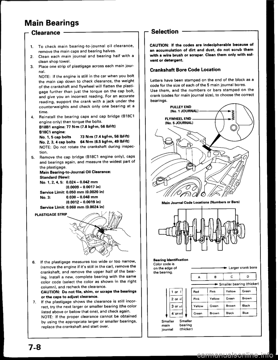
To check main bearing-to-journal oil clearance,
remove the main caps and bearing halves.
Clean each main journal and bearing half with a
clean shop towel.
Place one strip of plastigage across each main iour-
nal.
NOTE: lf the engine is still in the car when you bolt
the main caD down to check clearance, the weight
of the crankshaft and flywheel will flatten the plasti-
gage further than just the torque on the cap bolt,
and give you an incorrect reading. Fot an accurate
reading, support the crank with a iack under the
counterweights and check only one bearing at a
trme.
Reinstall the bearing caps and cap bridge (818C1
engine only) then torque the bolts.
81881 engine:77 N'm (7.8 kgf'm,56lbl'ft)
818C1 engine:
No. 1,5 cap bolts 73 N'm (7.'l kgt'm,56lbf'ftl
No. 2, 3, 4 cap bolts 6a N'm (6.5 kgf'm, 49 lbf'ftl
NOTE: Do not rotate the crankshaft during inspec-
tron,
Remove the cap bridge (818C1 engine only), caps
and bearings again, and measure the widest part oJ
the plastigage.
Main Bearing-to-Journal Oil Cl€arance:
Standard (Newl:
No. 1, 2, 4, 5: 0.024 - 0.042 mm
10.0009 - 0.0017 inl
Service Limit: 0.050 mm {0.0020 inl
No. 3:0.030 - 0.0,18 mm(0.0012 - 0.0019 inl
Ssrvice Limit: 0.060 mm {0.0024 inl
PLASTIGAGE STNIP
lf the plastigage measures too wide or too narrow,
(remove the engine if it's still in the car), remove the
crankshaft. and remove the upper half of the bear-
ing. Install a new. complete bearing with the same
color code (select the color as shown in the right
column), and recheck the clearance.
CAUTION: Do not file, shim, or scrapo ihe bo.rings
or the caps to adiust clearance.
lf the plastigage shows the clearance is still incor-
rect, try the next larger or smaller bearing (the color
listed above or below that one), and check again.
NOTE: lf the Droper clearance cannot be obtained
by using the appropriate larger or smaller bearings,
reolace the crankshaft and start over.
Selection
CAUTION: lf ths codes are indeciphorable becau3o ot
an lccumulation ol dirt and dust, do not gcrub thgm
with a wirs brush or gcrapsr. Clean them only with 3ol-
vont or doisrggnt.
Crankshaft Bore Code Location
Letters have been stamped on the end of the block as a
code for the size of each of the 5 main journal bores
Use them, and the numbers or bars stamped on the
crank (codes for main journal size), to choose the correct
bearings.
B..ring ld.ntificrtionColor code is
on the edge otthe bearang.Larger crank Dore
Mlin Joumal CodG Locttion3 (Numbors or gaBl
IcD
tr;;lIl
Itr-tl
lE;tl I tlHlt
I Lo.""li L
Smaller Smallermsin bearingjournal (thicker)
-------.r> smaller bearing (thicker)
G'een
Gre€^
GreenBlacr
GreenElackBlue
7-8
Page 149 of 1413

ConnectingRod Bearings
ClearanceSelection
CAUTION: lf the codss are indeciphsrable bocause of
an accumulation of dirt and dust. do not scrub tham
with a wiro brush or scraper. Clean them only with sol-
vont or dotetgenl.
Connecting Rod Code Location
A number has been stamped on the side of each con-
necting rod as a code for the size of the big end. Use it,
and the letters stamped on the crank (codes for rod jour-
nal size), to choose the correct bearings.
tF;l I tl-lf
liBor'rll I
lEalll t
I 1o.,,,'ll L
Smaller Smallerrod bearingjournal (thicker|
Half of number isstamped on bearingcap and the otherhalf is stamped onrod.
Conn.cting Rod Joumsl Codc LocatioN lLotteE or B.trl
Berring ldcntification
t23
Color code ison the edge ofthe bearing.Larger big end bore
Smaller bearing {thicker)
RedGr€€n
Elack
Bla€kBlue
1. Remove the connecting rod cap and bearing half.
2. Clean the crankshaft rod journal and bea.ing half
with a clean shoo towel.
3. Place the plastigage across the rod journal.
4. Reinstall the bearing half and cap, and torque the
nuts.
81881 sngino: 31 N'm 13.2 kgf.m,23 lbt'ft)
818C1 sngine: 4,1 N.m 14.5 kgf.m. 33 lbf'ft}
NOTE: Do not rotate the crankshaft during inspec-
tion.
Connecting Rod B€aring-to-Journal Oil Clcalancr:
8l88l ongine:
Standard (New): 0.020 - 0.038 mm
{0.0008 - 0.0015 in)
Servica Limit: 0.050 mm (0.0020 inl
818C1 engin€:
Standard (New): 0.032 - 0.050 mm
(0.0013 - 0.(XP0 inl
Service Limit: 0.060 mm (0.0024 in)
ll the plastigage measures too wide or too narrow,
remove the upper half of the bearing. install a new,
complete bearing with the same color code (select
the color as shown in the right column), and
recheck the clearance.
CAUTION: Do not file, shim, or scrape lhe bearing
or the capg tq adiust clgaranca.
lf the plastigage shows the clearance is still incor-
rect, try the next la.ger or smaller bearing {the color
listed above or below that one), and check clear-
ance again.
NOTE: lf the proper clearance cannot be obtained
by using the appropriate larger or smaller bearings,
reolace the crankshaft and stan over.
1.
PLASTIGAGE STRIP
Page 152 of 1413

EndPlay
NOTE; End play should be inspected before removing
crankshaft.
Push the crank firmly awav from the dial indicator, and
zero the dial against the end of the crank. Then pull the
crank firmly back toward the indicator; dial reading
should not exceed service limit.
Crankshaft End Play:
Standard (New): 0.10 - 0.35 mm
(0.04 - 0.01i| inl
S€rvic€ Limit 0.i15 mm (0.018 inl
. lf end play is excessive, inspect the thrust wash€rs
and thrust surface on the crankshaft. Replace pans as
necessary.
NOTE:
Thrust washer thickness is fixed and must not be
changed either by grinding or shimming.
Thrust washers are installed with grooved sides fac-
ing outward.
Crankshaft
lnspection
. Clean the crankshatt oil passages with pipe cleaners
or a suitable brush.
. Check the keyway and threads.
Alignment
Measure runout on all main journals to make sure the
crank is not bent.
The differ€nce between measurements on each jour-
nal must not be more than the service limit.
Crank3haft Total lndicatod Runout:
Bl8Bl engins:
Sisndod {Nsw): 0.03 mm {0.001 in) max.
Sorvice Limit: 0.05 mm {0.002 inl
818C1 engin€:
Standard {Nsw): 0.020 mm (0.0008 in} mar.
SGrvice Limits: 0.030 mm 10.0012 in)
OIAL INDICATORRotate tlvo completerevolutions.
Support with lathe-
7-12
Page 153 of 1413

Out-ot-Round and Taper
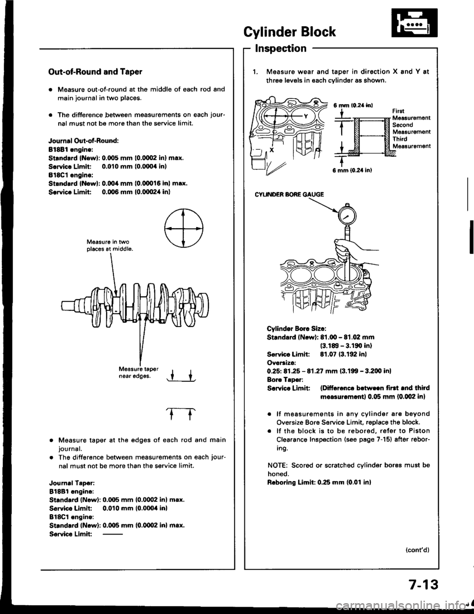
. Measure out-of-round at the middle of each rod and
main journal in two places.
. The difference between msasurements on each jour-
nal must not be more than the se.vice limit.
Journal Oul-of-Round:
Bt8Bi.ngine:
Strndrrd (Now): 0.(x15 mm (0.0002 inl m!x.
Scrvicr Limit 0.010 mm (o.fixx inl
Bl8Cl cngins:
Strnd.rd {Nowl: 0.004 mm (0.(XD16 inl m!x.
Sorvicc Limit 0.qt6 mm {0.qx!2,1 in}
near edggs..t +
Measure taper at the edges of each rod and main
journal.
The difference between measurements on each jour-
nal must not be more than the service limit.
Journal Tapor:
8l8Bl angino:
Standard (Newl: 0.q)5 mm l0.0(Xl2 inl m.x.
Sorvico Limit 0.010 mm (0.0004 inl
BlSCl ongino:
Standrrd (Now): 0.005 mm (0.0002 inl m8x.
Scrvic€ Limit
frrgtMeaauremonlSecondMoa6urgmontThi.dM063uremgnt
G mm {0.24 in}
CYUNDER BORE GAUGE
Cyllndor Borr Siz.:
Standard (Ncwl: 81.q!- 81.02 mm(3.18, - 3.190 inl
Scrvicr Limh: 81.07 (3.192 in)
Ovar3izc:
O.25t 81.25 - 81.27 mm (3.199 - 3.200 inl
Borc Tlpor:
Scrvice Limit (Ditfcrcncc bctw!.n firtt tnd third
moasurcm.ntl 0.115 mm (0.002 in)
. lf moasur€ments in any cylindsr are beyond
Oversize Bore Service Limit, rsglace the block.
. lf the block is to be rebored, refer to Piston
Clearance Inspection (see page 7-151 after rebor-
ing.
NOTE: Scored or scratched cylinder bores must be
honed.
Rcboring Limil: 0.25 mm (0.01 inl
(cont'd)
Gylinder Block
Inspection
1. Measure wear and taDer in dirsction X and Y at
three levels in each cvlindsr as shown.
6mm
Y
7-13
Page 154 of 1413

Cylinder Block
Inspection (cont'dl
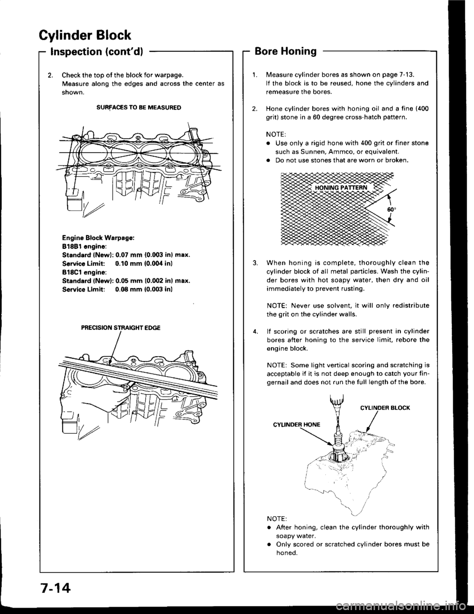
2.Check the top of the block for warpage.
Measure along the edges and across the center as
snown.
SURFACES TO BE MEASURED
Engine Block Warpsgc:
81881 ongine:
Standard lNewl: 0.07 mm {0.003 inl max.
Service Limil: 0.10 mm {0.00,1inl
B18Cl engine:
Standard (New): 0.05 mm 10.002 inl max.
Service Limit 0.08 mm {0.003 inl
Measure cylinder bores as shown on page 7-13.
lf the block is to be reused, hone the cylinders and
remeasure the bores.
Hone cylinder bores with honing oil and a fine (400
grit) stone in a 60 degree cross-hatch pattern.
NOTE:
. Use only a rigid hone with 400 grit or finer stone
such as Sunnen, Ammco, or equivalent.
a Do not use stones that are worn or broken.
When honing is complete, thoroughly clean the
cylinder block of all metal panicles. Wash the cylin-
der bores with hot soapy water, then dry and oil
immediately to prevent rusting.
NOTE: Never use solvent, it will only redistribute
the grit on the cylinder walls.
lf scoring or scralches are still present in cylinder
bores after honing to the service limit, rebore the
engine block.
NOTEr Some light venical scoring and scratching is
acceptable if it is not deep enough to catch your fin-
gernail and does not run the full length of the bore.
CYLINDER HONE
. After honing, clean the cylinder thoroughly with
soapy water.
. Only scored or scratched cylinder bores must be
noneo.
7-14
Page 155 of 1413

Pistons
Inspection
1. Check the oiston for distortion or cracks.3, Calculate the difference betw€on cvlinder bore
diameter on (see page 7-13) and piston diametsr.
Pbton-io"Cy'indor Clea18nco:
Stsndard (Nrwl: 0.010 - 0.0/O mm
{o.ofira - 0.0016 in}
S.rvic. Limit: 0.05 mm {0.002 in)
NOTE: lf the cylinder is bored, an oversized piston
must be used,
2. Moasur€ the piston diameter at a point l5 mm
(0.6 in) from the bottom of the skin.
Pbion Diamat6r:
Standard lNowl: 80.S - 80.99 mm(3.188 - 3.189 inl
Sorvica Limit 80.97 mm (3.188 in)
lf the clearance is near or €xc€eds the service limit,
inspect the piston and cylinder block for excessive
wear.
Ov.rsizc Pilton Diamcter:
O.25t 81,23 - 81.21|rnm {3.1980 - 3.198'l in)
rKI
7-1
Page 157 of 1413

I
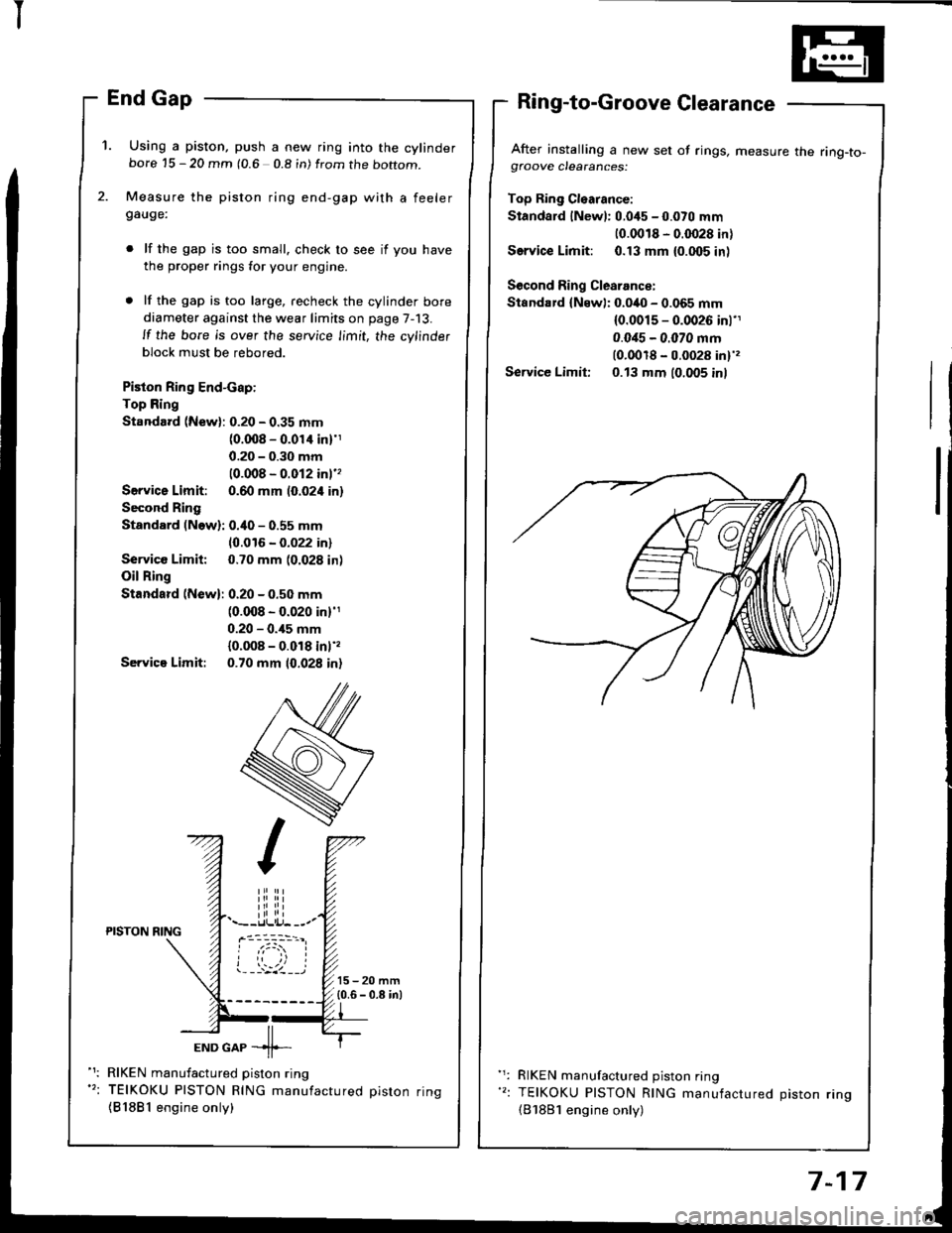
'1. Using a piston, push a new ring into the cylinderbore 15 - 20 mm (0.6 0.8 in) from the boftom.
Measure the piston ring end-gap with a feelergauge:
lf the gap is too small. check to see if you have
the proper rings for your engine.
lf the gap is too large, recheck the cylinder bore
diameter against the wear limits on page 7-13.
ll the bore is over the service limit, the cylinder
block must be rebored.
Piston Ring End-cap:
Top Ring
Standard (New): 0.20 - 0.35 mm(0.008 - 0.01'l inl'1
0.20 - 0.30 mm
10.008 - 0.012 inl''
Servica Limit: 0.60 mm (0.024 in)
Second Ring
Standard (Now): 0.40 - 0.55 mm
10.016 - 0.022 in)
Service Limit: 0.70 mm (0.028 in)
Oil Ring
Standard (New): 0.20 - 0.50 mm(0.008 - 0.020 in)'1
0.20 - 0.,15 mm
{0.008 - 0.018 inl',
Servica Limit: 0.70 mm 10.028 in)
After installing a new set of rings, measure the ring-to-gfoove clearances:
Top Ring Cl€arance:
Standard lNewl: 0.045 - 0.070 mm
10.0018 - 0.0028 in)
Service Limit: 0.13 mm {0.005 inl
Second Ring Clearance:
Standard {Newl: 0.040 - 0.065 mm(0.0015 - 0.0026 inl'1
0.0i15 - 0.070 mm(0.0018 - 0.0028 in)',
Service Limit: 0.13 mm (0.005 inl
iliiii.--r.llli.j- --.-PISTON NING
ioi
---'z llEND GAP -11--
RIKEN manufactured piston ring
TEIKOKU PISTON RING manufactured oiston rinq
{81881 engine only)
RIKEN manufactured piston ring
TEIKOKU PISTON RING manufactured Diston rino(B'1881 engine only)
7-17
Page 171 of 1413

Engine Oil
lnspection
Check engine oil with the engine off and ths cal
parked on level ground,
Make cenain that the oil level indicated on the dip-
stick is between the upper and lower marks.
lf the l€vel has dropped close to the lower mark, add
oil until it reaches the upper mark.
CAUTION: Inssrt lho dipstick carotully to avoid
bending it.
3.
Replacement
CAUTION: Remova tho drain plug cal€fully whilo the
ongine is hot; the hot oil may cause scalding.
1. Warm up the engine.
2, Drain the engine oil.
3. Reinslallthe drain plug with a new washer, and refill
with the recommended oil.
CAUTION: Do not ovortighton tho drain plug.
(cont'd)
RequirementAPI Service Grade: Use "Energy
Conserving ll" SG or SH grade oil.
SAE 5W-3O Drefered.
CapacityB18B1 engine:
3.51 (3.7 US qt, 3.1 lmp qtl
at oil change.
3.8 t (4.0 US qt, 3.3 lmp qt)
at change. including filter.
4.6 I 14.9 US qt. 4.0 lmp qt)
after engine overhaul.
B18Cl engine:
3.7 f (3.9 US qt, 3.3 lmp qt)
at oil change.
4.O t 14.2 US qt, 3.5 lmp qt)
at change, including filter.
4.a I (5.1 US qt, 4.2 lmp qt)
after engine overhaul.
ChangeEvery 7,5OO miles (12,OOo km) or
6 months
8-5