Page 339 of 1413

InspectionReplacement
Flywheel, Flywheel Bearing
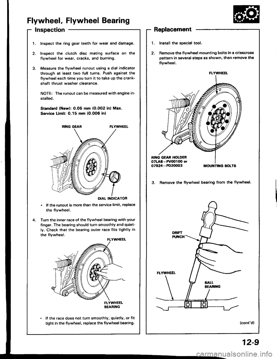
Inspect the ring gear teeth for wear and damage.
Inspect the clutch disc mating surface on the
flywheel fo. wear, cracks, and burning.
Measure the flywheel runout using a dial indicator
through at least two full tu.ns. Push against the
Ilywheel each time you turn it to take up the crank-
shaft thrust washe. clearance.
NOTE; The runout can be measu.ed with engine in-
stalled.
Standard (ttlervl: O.O5 mm (O.002 inl Max.
Service Limit: 0.15 mm 10.006 inl
RING GEABFLYWHEEL
DIAL II{DICATOR
It the runout is more than the service limit, leplace
the flvwheel.
Turn the inner race of the flywheel bearing with your
finger. The bearing should turn smoothly and quiet-
ly, Check that the bearing outer race fits tightly in
the flvwheel.
FLYWHEELBEARING
It the race does not turn smoothly, quietly, or fit
tight in the flywheel, replace the flywheel bearing.
Install the special tool.
Remov€ the flywhe€l mounting bolts in a criascross
pattern in several steps 8s shown, then remove the
tlywheel.
MOUI{TII{G BOLTS
3. Remov€ the flywheel bsaring from th€ tlywheel.
(cont'd)
FLYWHEEL
12-9
Page 345 of 1413

- Transmission Oil
NOTE: Check the oil with the engine OFF, and the car on
level ground.
1. Remove the oil filler plug, then check the level and
Maintenance
condition of the oil.
OIL FILLER PLUG44 N.m lia.5 kgf.m,
ORAIN PLUG$ N.m 14.0 kgf.m.29 lbf.fr)
33 tbtftlProper Level
2. The oil level must be up to the filler hole. lf it is
below the hole. add oil until it runs out, then rein-
stall rhe oil filler plug.
3. lf the transmission oil is dirty, remove the drain
plug and drain the oil.
4. Reinstall the drain plug with a new washer, and
refillthe transmission oil to the proper level.
NOTE: The drain plug washer should be replaced at
every oil change.
5 Reinstall the oil filler plug with a new washer.
OilCapacity
2.2 ( ''2.3 US.qt,1.9 lmp.qt) at oil chang€.
2-3 I l2.1Us.ql,2.0lmp.qtl at oyerhaul.
Use only SAE 10 w - 30 or '10 W - 40, API Service
SF or SG grade.
OIL FILLER PLUGa4 N.m l{.5 kgf.m, 33 lbf.ftl
Back-up Light Switch
Replacement
NOTE: To check the back-up light switch,
1. Disconnect the connector, then rem(
light switch connector trom the conn
2. Remove the back-up light switch.
BACX-UP LIGHT SWITCH25 N.m 12.5 kg[.m, 18 lbf.ftl
lnstall the new washer and the back-
Check the transmission oil level (see
Replace.
/itch, see section 23.
remove the back-up
]onnector clamp.
-up light switch.
) page 13-3).
Replace.
13-3
Page 354 of 1413
Measure the clearance between the reverss idler
gear and the reverse change holder.
Standard: 0.5 - 1.1 mm (0.02 - 0.04 inl
Sorvico Limit: 1.8 mm (0.07 inl
4.lf the clearance is more than the service limit, mea-
sure the width ofthe reverse change hold6r.
St.ndrrd: 13.0 - 13.3 mm (0.512 - 0.52/t inl
lf the width is not within the standard, replace
the reverse change holder with a new one.
lf the width is within the standard, reolaco the
reversa idler gear with a new one.
REVERSE CHA'{GE HOLDER
REVERSE CHANGE HOTI'ER
Reverse Change Holder, Reverse ldler Gear
Clearance Inspection lcont'd)Removal
1. Removo the reverse change holder.
2. Remove the revorss idler g€ar, th€ rev6rs6 idlsrgear shaft, and the washor {B18Cl engine}.
REVERSE IDI.TRGEAF SHAFT
13-12
REVERSE CHAMiE HOII'ER
Page 355 of 1413

Change Holder Assembly
Clearance Inspection
Measure the clearance between the shift piece and
the shift arm holder.
Silndrd: 0.1 - 0.3 mm (0.004 - 0.012 inl
Scwic. Limit: 0.6 mm (0.02 inl
It the cloarance is more than the service limit, mea-
sure th€ width of the groove in the shift piece.
Stlndffd: 8.1 - 8.2 mm (0.319 - 0.323 inl
ll the width of the groove is not within the stan-
dard, replsce the shift piecs with a new one.
lf the width of the groove is within the standard.
roolace the shift arm holder with a new one.
SHIFT PIECE
SHIFT ARM HOI.I'ER
SHIFT PIECE
INTERLOCK
{
3. Measure the clearance between the select 8rm and
the interlock.
Standlrd: 0.05 - 0'25 (0.002 - 0.010 in)
Scrvica Limit 0.5 mm (0.02 in)
4. lf the clearance is more than the service limit, mea-
sure the width ot the interlock.
Stlndrrd: 9.9 - 10.0 mm (0.391t - 0.39a in)
lf the width is not within the standard. replace
the interlock with a new one.
lf the width is within the standard, replace the
select arm with a new one.(cont'd)
13-13
Page 356 of 1413

Change Holder Assembly
Clearance Inspection {cont'd}
7, Measure the clearance between the select arm
the 10 mm shim.
Stsndard: 0.01 - 0.2 mm (0.0004 - 0.008 inl
8. lf the clearance is not within the standard. select
and install the appropriate 10 mm shim for the cor-
rect clearance from the chan below.
10 mm Shim
SETICT ABM
10 mm SHIM
Part NumbsrThickn€ss
24435-689-0000.8 mm (0.03'l in)
B24436-689-000'1.0 mm (0.039 in)
24437-689-0001.2 mm (0.047 inl
24438-689-0001.4 mm {0.055 in)
24439-689-0001.6 mm (0.063 in)
13-14
SHIFT ARM HOLDER
9. Measure the clearance between the shift arm holder
and the change piece.
Standard: 0.05 - 0.35 10.002 - 0.01i1 in)
Sorvico Limit: 0.8 mm (0.03 in)
ll the clearance is more than the service limit. mea-
sure the groove of the change piece.
Standafd: 12.05 - 12.15 mm {0.47ilil - 0.iU83 in)
lf the groove is not within the standard, replace
the change piece with a new one.
lf the groove is within the standard, replace the
shift arm holder with a new one.
10.
Page 357 of 1413
11.Moasure th€ clsarance between the s6l6ct arm 8nd
tho change piece.
Sundrrd: 0.05 - 0.35 mm (0'002 - 0'014 in)
S.rvic. Limit 0.5 mm 10.02 Inl
lf the clesrance is more than the service limit, mea-
sure the width ofthe change Piece.
Strndrrd: 12.05 - 12.15 mm {0./17,11 - o.'U&l in)
CHANGE PIECE
lf ths width is not within the standard, replace
the change piec€ with a n€w one.
lf the width is within the standard, replaco th€
select arm with a new one.
Removal
Removs the shift piece shaft, then remove the shift
pieca and the interlock.
SHIFT PIECE SHAFT
2. Remove the change holder assembly.
12.
SEI.ECT ARl,l
CHANGE HOLDER ASSEMBLY
13-15
Page 362 of 1413

Shift Fork Assembly
Clearance Inspection
NOTE: The synchro sl€€v€ and the synchro hub should
be replac€d as a set,
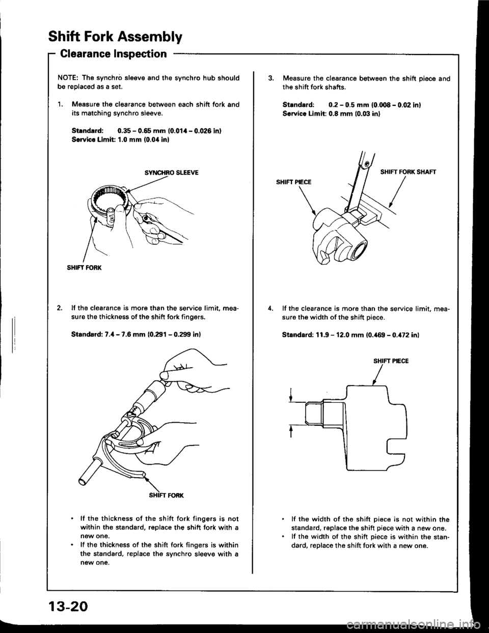
1. Measure th€ clearance between each shift fork and
its matching synchro sleeve.
Strndud: 0.35 - 0.65 mm (0.014 - 0.026 in)
S€rvico Limit 1.0 mm (0.0'l in)
SHIFT FORK
lf the clearance is more than the service limit. mea-
sure the thickness of the shift fork finoers.
Standard: 7.4 - 7.6 mm (0.291 - 0.299 inl
lf the thickness of the shift fork fingers is not
within the standard, replace the shift fork with a
now one.
lf the thickness of the shift lork fingers is within
the standard, replace the synchro sleeve with a
new one.
SYNCHRO SLEEVE
13-20
Measure the clearance between the shift Diece and
the shift fork shafts.
Strndard: 0.2 - 0.5 mm {0.qt8 - 0.02 in]
S.rvico Limit: 0.8 mm (0.03 inl
SHIFT PIECE
lf the clearance is more than the service limit, mea-
sure the width of the shift piece.
Stsndard: 11.9 - 12.0 mm (0.469 - 0.472 in)
lf the width of the shift piece is not within the
standard, rsplace the shift piece with a new one.
lf the width of the shift piece is within the stan-
dard, replace the shift fork with a new one.
IFT FORK
/
Page 364 of 1413
Mainshaft Assembly
Clearance Inspection
NOTE: lf replacement is required. always replace the
synchro sleeve and the synchro hub as a set.
1. Measure the clearance between 2nd and 3rd gears.
Standard: 0.06 - 0.21 mm {0.002 - 0.008 inl
Ssrvica Limit: 0.3 mm (0.01 in)
13-22
Engine Type818C181881
Standard34.92 - 34.97 mm
(1.375 - 1.377 in)
34.42 - 34.47 mm
(1.355 - 1.357 in)
Service Limit34.8 mm
(1.370 in)
34.3 mm(1.350 in)
2. lf the clearance is more than the service limit, mea-
sure the thickness of 3rd gear.
lf the thickness of 3rd gear is less than the ser-
vice limit, replace 3rd gear with a new one.
lf the thickness of 3rd gear is within the service
limit, replace the 3rd/4th synchro hub with a new
one.
3RD GEAR