1994 HONDA INTEGRA service
[x] Cancel search: servicePage 489 of 1413

LOCK.UP CONTROLSOLENOID VALVE4TI{ CLUTCH PRESSUREINSPECTION HOLE
SHIFT CONTROLSOLENOID VALVEASSEMBLY PROTECTOR
3RD CLUTCH PRESSUREINSPECTION HOLEINSPECTION HOLE
PRESSUNESELECTOR
POStTtONSYMPTOMPROBABLE CAUSEFLUID PRESSURE
StandardService Limit
2nd ClutchENo or low
2nd pressure
2nd Clutch460-88O kPa(4.7 -9.O kgtlcmt,
67- 130 psil
varies with throttle
openrn9
41O kPa
{4.2 kgf/cm,, 60 psi}
with throttle control
lever released
78O kPa
l8.O kgtlcm,, 1'lO psil
with throttle control
lever more than 3/1 6
opened
3rd ClutchNo or low
3rd pressure
3rd Clutch
4th ClutchNo or low
4th pressure
4th Clutch
(cont'd)
14-97
Page 540 of 1413

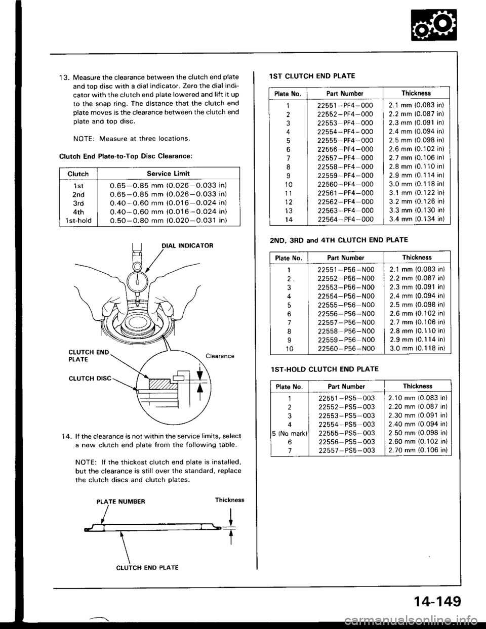
'13. Measure the clearance between the clutch end plate
and top disc with a dial indicator. Zero the dial indi-
cator with the clutch end plate lowered and lift it up
to the snap ring. The distance that the clutch end
plate moves is the clearance between the clutch end
plate and top disc.
NOTEr Measure at three locations.
Clutch End Plate-to-Too Disc Clearance:
1 4. lf the clearance is not within the service limits, select
a new clutch end plate lrom the following table.
NOTE: It the thickest clutch end plate is installed,
but the clearance is still over the standard, replace
the clutch discs and clutch Dlates.
Thickn€ss
ClulchService Limit
lst
2nd
3rd
4th
1st-hold
O.65 o.85 mm (O.026 O.O33 in)
O.65 - O.85 mm {O.026-O.O33 in)
O.4O-O.60 mm (0.O16 o.O24 in)
0.4O-0.60 mm (0.016-0.024 in)
0.50-0.8O mm {O.02O-0.031 in}
IAL INDICATOR
PLATE NUMBER
CLUTCH END PLATE
14-149
lST CLUTCH END PLATE
2ND- 3RD and 4TH CLUTCH END PLATE
lST.HOLD CLUTCH END PLATE
Plate No.Part NumberThickness
1
2
3
4
5
6
7
8
I
10
111)
IJ
14
22551-PF4-000
22552-PF4 000
22553 PF4 000
22554-PF4-OOO
22555 PF4-000
22556 PF4-000
22557 -PF4 000
22558-PF4 000
22559- PF4- 000
22560-PF4 000
22561 PF4-000
22562-PF4 000
22563-PF4 000
22564 PF4-OOO
2.1 mm 10.083 in)
2.2 mm (0.087 in)
2.3 mm (0.091 in)
2.4 mm (0.094 in)
2.5 mm (0.098 in)
2.6 mm {0.102 in}
2.7 mm i0.106 in)
2.8 mm (0.110 in)
2.9 mm (0.1 14 in)
3.0 mm (0.1 18 in)
3.1 mm (0.1 22 inl
3.2 mm {0.126 in}
3.3 mm (0.1 30 in)
3.4 mm (0.134 in)
Plate No.Part NumberThickness
1
2.
3
4
5
6
7
8
I
10
22551 P56,N00
22552-P56-N00
22553-P56-N00
22554- P56 -N00
22555-P56 N00
22556 Ps6- N00
22557 - P56 N00
22558 P56-N00
22559-P56 NOO
22560 P56-N00
2.1 mm (0.083 in)
2.2 mm (0.087 in)
2.3 mm (0.091 in)
2.4 mm (0.094 in)
2.5 mm (0.098 in)
2.6 mm {0.102 in)
2.7 mm {0.106 ini
2.8 mm (0.110 in)
2.9 mm (0.1 14 in)
3.0 mm (0.1 18 in)
Plare No.Part NumberThicknEss
1
2
3
4
5 (No mark)
6
7
22551-PS5 003
22552 PS5-003
22553-PS5 003
22554-PS5-003
22555-PS5-003
22556 PS5-003
22557 PS5-003
2.10 mm (0.083 in)
2.20 mm (0.087 in)
2.30 mm (0.09'1 in)
2.40 mm (0.094 in)
2.50 mm {0.098 in)
2.60 mm {0.102 in}
2.70 mm (0.106 in)
Page 608 of 1413

Steering
Special Tools ............. 17-2
Component Location
lndex ................ ...... 17-3
System Description
Ff uid Flow Diagram ......................... 17 -1
Steering Pump ................................. 17-5
Steering Gearbox ............................. 17-7
Troubleshooting
General Troubleshooting ................ 17-10
Noise and Vibration ......................... 17-14
Fluid Leaks ............. 17-16
Inspection and Adiustment
Steoring Operation .......................... 17 -14
Power Assist Check
with Car Parked ........................... 17-18
Steering Linkage and Gearbox ....... 17-19
Pump Beh .............. 17-20
Rack Guide Adjustment ............. ..... 17-21
Ff uid Replacement ...................... ..... 17 -21
Pump Pressure Check .................. .... 17 -22
Ffuid Leakage lnspection ................ 17-23
+ Steering Wheel
Removal ..,,,,,,,........ 17-24
Disassembly/Reassembly ............... 17 -25
fnstallation ,......,,,,,. 17-26
* Steering Column
Removaf .................17-28
Inspection .............. 17-30
Installation ............. 17-31
Power Steering Hoses. Pipes
Replacemont ......... 17-3tl
Power Steering Pump
Removal ................. 17-35
Disassembly .......... 17-35
Reassembly ........... 17-'10
lnstallation ........,..., l7-tltl
Steering Gearbox
Removaf .,.,............. 17-45
Disassembly .......... 17-/E
Reassembly ........... 17-53
lnstallation ............. 17-63
Ball Joint Boot Replacement .......... 17-65
SUPPLEMENTAL RESTRAINT SYSTEM {SRSI
The Integra SRS includes a driver's airbag. located in the steering wheel hub, In addition, all models except the
RS model for Canada have a front passenger's airbag located in the dashboard above the glove box. Information
necessarv to safely service the SRS is included in this Service Manual. ltems marked with an asterisk {') on the
contents page include, or are located near, SRS components. Servicing. disassembling or replacing these items
will require special precautions and tools, and should therefore be done by an authorized Acura dealer.
a To avoid rsndering ths SRS inoporative, which could load to po.sonal iniury 01 d€ath in th€ event ot a ssvare
lrontal collision, all SRS service work muat be performod by an authorizod Acura deal6t.
a lmploper service procodules. including incorloct romoval and installation of the SRS, could lead to personal iniu-
ry caused by unintontional activation ot the airbags.
a All SRS elsctdcal wiring harnesses ara covorod with ysllow insulation. Rolalod compon€nts 8re locatsd in tho
stse ng column, tront console, dashboard, and dashboard lower panel, and in the dashboard above the glove
box. Do not use oloctrical tost equipmoni on thosa cilcuits.
NOTE: The original radio has a coded thett protection circuit. Be sure to get the customer's code number before
- disconnecting the battery.- removing the No. 32 (7.5 A) tuse from the under-hood fuse/relay box.
- removing the radio.
Alter service, reconnect power to the radio and turn it on. When the word "CODE" is displayed' enter the cus-
tomer's 5-digit code to restore radio operation.
Page 610 of 1413

Component Location
lndex
Powar Siooring:
NOTE:
a
a
It an intact airbag ass€mbly has been r€moved from a scrapped car or has been found defective or damaged during
transit. storage or service, it should be doploy€d (see section 23).
Before removing tho gearbox, remove ths ignition key to keep the steering shaft Jrom turning.
After installing the gearbox, check ths whe€l alignment and adiust if necessary.
CAUTION:
. All SRS aloctricll wiring h!m!|$a rrc covcred with
yrllow in3uhtion.
. 8€for€ disconnocling lny ptrt ol thc SRS wiro h!r'
ne*r, connect thc lhort conncctor{3l.
. Rcplsce lhc ontira ttfact d SRS harnccc a$embly il
it hs3 !n oprn circuh 01 dtm!9.d wiring.
SIEERING COLUiINRemoval, page 17-28Inspection, pago 17-30Installation, p6ge 17-31rcNMON SwlTCHSee s6ction 23
STEERII{G GEARBOXRack Guide Adjustment, pag.11-21
Removal, pags 17-45Diossombly, page 17-{8Bea65€mbly, page 17-53Installation, page 17-63
POWEN STEERING PUMPPump Beft Inspoction. page 17-2OPump Eeft Adjustm6nl, pago 17-2OPump Pressurg Ch€ck, page 17-22Removai, p6go 17-35Disassembly, p3gs 17-35Reassombly, psge l7-40lnstallation, page 17-44
STEERING WHEELRemoval. page 17-24Oisassembly/Reassembly, pageInstallation, page 17-2617-25
TIE'ROD END BALL JOINTBall Joint Eoot Replacement, page 17-63
17-3
Page 625 of 1413

Place the front wheels in the straight ahesd position and
measure the distSnce the steering wheel can be turned
without moving the front wheels.
ROTATIONAL PLAY: 0 - 10 mm l0 - o.:Xl inl
lf the plsy excseds the service limit, psrform rack guide
adjustment (see page 17-211.
lf the play is still excessive after rack guide adjustment,
inspect the stsering linksgo and gearbox as described
on the next page.
ROTANONAL PLAY
Inspection and Adjustment
Steering OperationPower Assist Gheck with
817-1
Gar Parked
1. Check the power steering fluid level (see page 17-
21) and pump belt tension lsee page l7-20).
2.Start the engine, allow it to idle, and turn the steer-
ing wheel from lock-to-lock sev€ral times to warm
uo the fluid.
Attach a spring scale to the steering wheel. With the
engine idling and the car on a clean, dry floor, pull
the scale as shown and read it as soon 8s the tires
begin to turn,
il. The scal6 should read no more than 33 N (3.4 kgf,
7.5 lbf). lf it reads more or less, ch€ck the gearbox
and pump.
Page 632 of 1413

Removal
Disconnect the connectors trom the horn and cruise
control sevresume switches.
HORN
Disassembly/Reassembly
8.Remove the steering wheel nut.
Remove the steering wheel by rocking it slightly
from side-to-side as you puil steadily with both
hands.STEERING WHEEL
STEERING WHEELNUTReplace.
@ store a removed airbag assembly with
the pad 3urfacs up. lf the airbag is improperly stored
face down, accid€ntal daployment could prop€l tho unit
with enough forca to cause serious iniury.
NOTE: lf an intact airbag assembly has been removed
from a scragoed car or has been found defective or
damaged during transit. storage or service, it should be
deployed (see section 23).
TORX6 BOLT
CAUTION:
C8r€{ully inspoct ihe sirbag assombly betors install.
ing. Do not install an airbag ass6mbly that 5how3
signs ol boing dtopped or improperly handled, such
as dents, crack3 or deformation.
Always k€gp tho short connector on the aitbag con-
nector when ths harnegg i9 disconnected.
Do not disassemble or tamper with the airbag as-
sombly.
STEERING WHEEL
10 N.m {1.0 kgf m, Tlbt.ttl
t
TORX6 BOLT10 N.m {1.0 kgf.m, 7lbf.ft)
LID
\s
SPACER
/
@
CRUISE CONTROL SET/NESUME SWITCHES
CRUISE CONTROL SET/RESUME SWITCHES COVER
HORN CONTACT PI-ATE
17-25
Page 1001 of 1413

Dashboard
Component Removal/lnstallation (cont'dl
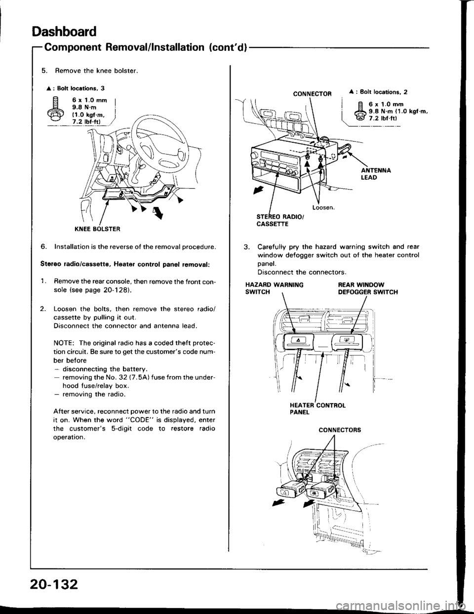
5. Remove the knee bolster.
: Bolt locations, 3
fi 6rt.omm
6 i;i'i#.,7.2 tbr.ftl
?
KNEE
6. Installation is the reverse of the removal Drocedure.
Stol€o radio/cassette, Heater control panal removal:
1 . Remove the rear console, then remove the front con-
sole (see page 20-128).
Loosen the bolts, then remove the stereo radio/
cassette by pulling it out.
Disconnect the connector and antenna lead.
NOTE: The original radio has a coded theft protec-
tion circuit, Be sure to get the customer's code num-
ber belore- disconnecting the battery.
removing the No. 32 17.5A) fuse from the under-
hood fuse/relay box.- removing the radio.
After service, reconnect power to the radio and turn
i1 on. When the word "CODE" is displayed. enter
the customer's 5-digit code to restore radio
operation.
20-132
CONNECTOR
CASSETTE
i Bolt locations. 2
6 x 1.0 mm9.8 N.m {1.0 kgl.m,
3, Carefully pry the hazard warning switch and rear
window defogger switch out of the heater control
Daner.
Disconnect the connectors.
HAZARD WARNINGswtTcHREAR WINOOWDEFOGGER SWITCH
Page 1005 of 1413

Dashboard
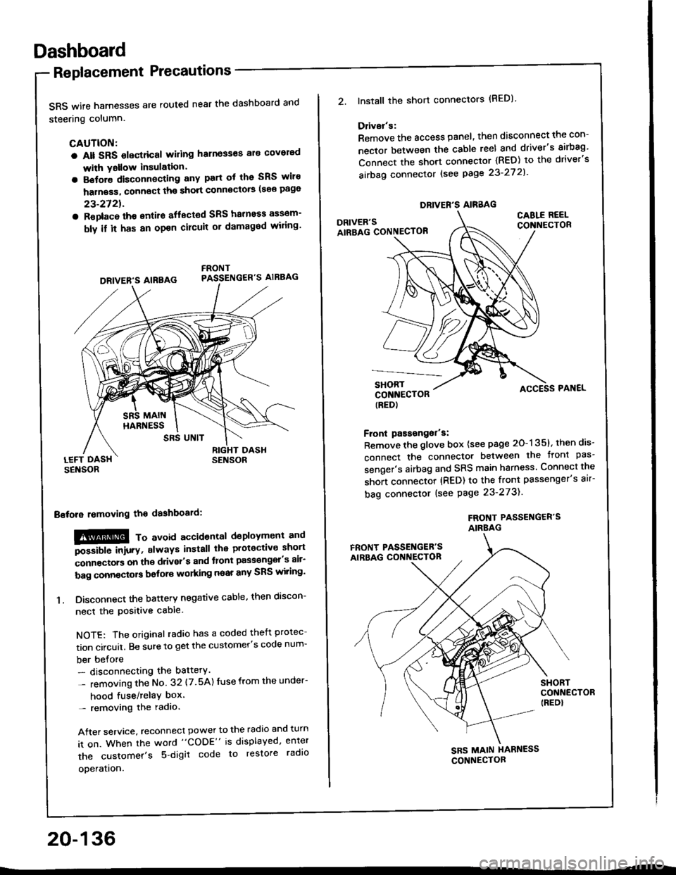
Replacement Precautions
SRS wife harnesses are routed near the dashboard and
steering column.
CAUTION:
a Alt SRS olectrical wiling harness€s ale covorad
with Yollow insulation.
a Botore disconnecting any part ot the SRS wiro
harness, connect ths short connscto6 (see page
23-2721.
a Roplac6 ih€ entiro aflectod SRS halnoss assem-
bly il it has an opon cilcuit or damagod wiling'
LEFT DASHSENSOR
Bstora lomoving the dashboaid:
!@@ To avord accioenlal dsployment and
""iUU inir.v, always install the plotoctive short
;onnectors on the driver's and tlont pass€ngel's air-
bag connectors bolors working near any SRS wiring'
1. Disconnect the battery negative cable, then discon-
necl the positive cable.
NOTE: The original radio has a coded theft protec
tion circuit. Be sure to get the customer's code num-
ber before- disconnecting the battery.
- removing the No 32 (7.5A) Iuse from the under-
hood fuse/relaY box'- removing the radio.
After service, reconnect power to the radio and turn
it on. When the word "CODE" is displayed, enter
the customer's 5 digit code to restore radlo
ooeration.
DRIVER'S AIREAG
SRS UNIT
20-136
DRIVER'S AIRBAG
2.lnstall the short connectors (RED)
Ddvar's:
Remove the access panel, then disconnect the con-
nector between the cable reel and driver's airbag'
Connect the short connector (RED) to the driver's
airbag connector lsee page 23-27 2l'
DRIVER'SAIRBAG CONNECTOB
CABLE REELCONNECTOR
SHORTCONNECTOR(RED)
Front passongor's:
Remove the glove box {see page 20-135}, then dis-
connect the connector between the tront pas'
senger's airbag and SRS main harness Connect the
short connector (RED) to the front passenger's air-
bag connector (see Page 23-273).
FROf{T PASSENGER'SAIRBAG
ACCESS PAI{EL
FRONT PASSET{GER'SAIRBAG CONNECTON
SHORTCONNECTOR(REDI
SBS MAIN HARNESS
CONNECTOR