Page 1379 of 1413

Supplemental Restraint System (SRS)
Steerin g-related Precautions
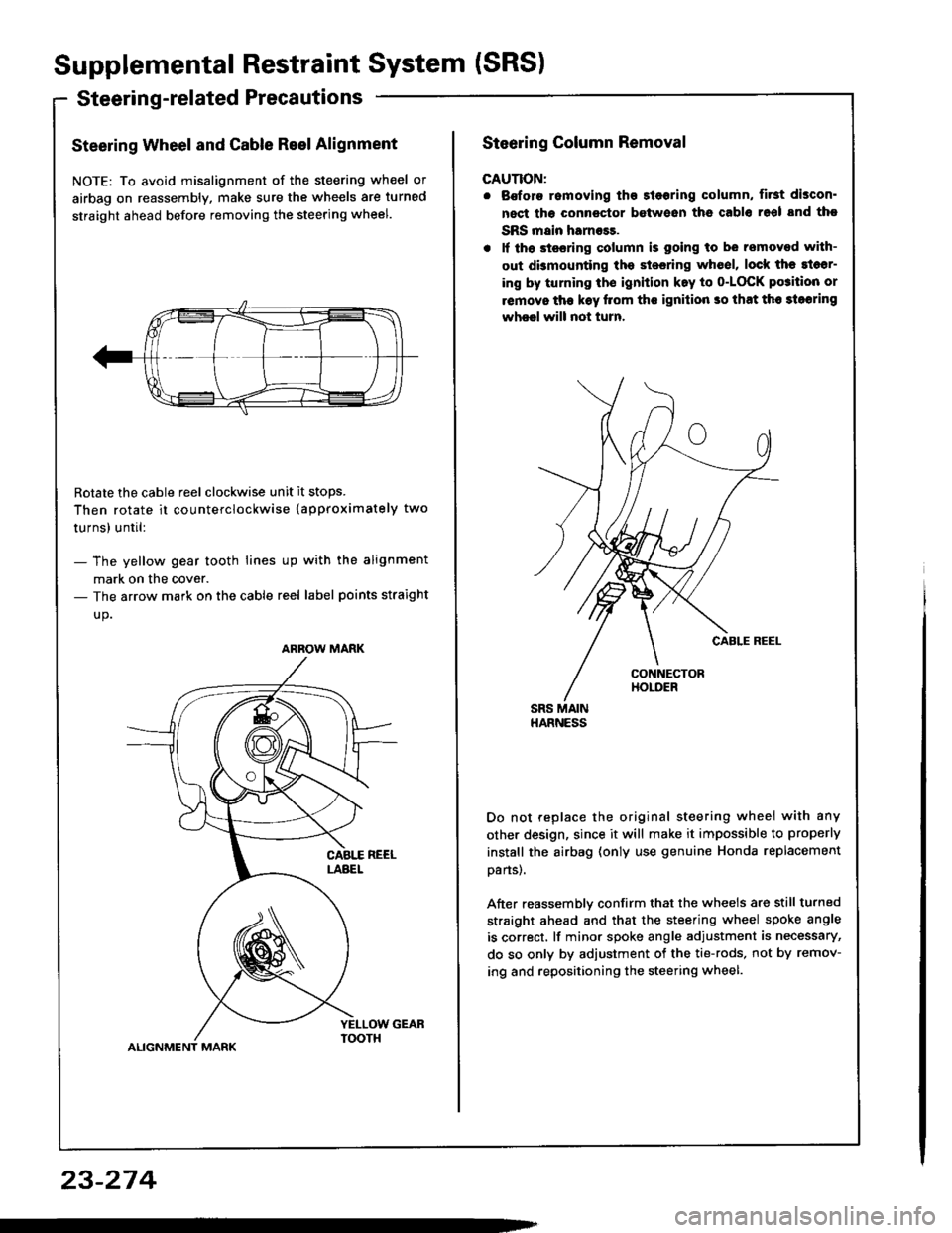
Steering Wheel and Cable Reel Alignment
NOTE: To avoid misalignment of the steering wheel or
airbag on reassembly, make sure the wheels are turned
straight ahead before removing the steering wheel.
Rotate the cable reel clockwise unit it stops.
Then rotate it co u nterclockwise (approximately two
turnsl until:
- The yellow gear tooth lines up with the alignment
mark on the cover.- The arrow mark on the cable reel label points straight
up.
ALIGNMENT MARK
ARROW MARK
23-274
Steering Column Removal
CAUTION:
. Bofore romoving tho 3l6oring column, first discon'
nect tha connector between ths cablo 16ol snd tho
SRS main harness.
. lf th6 stssring column is going to be removed with-
out dbmounting the stesring wh6el, lock the sl6sr-
ing by turning th€ ignition k.y to o-LOCK po3ition or
removo tha k€y llom ths ignilion so that th6 3loaring
wheel will not turn.
Do not replace the original steering wheei with any
other design, since it will make it impossible to properly
instsll the airbag (only use genuine Honda replacement
oans).
After reassemblv confirm that the wheels are still turned
straight ahead and that the steering wheel spoke angle
is correct, lf minor spoke angle adjustment is necessary,
do so only by adjustment of the tie-rods, not by remov-
ing and repositioning the steering wheel.
Page 1408 of 1413

GAUTION:
o Eatora instdling tho steoring whosl, lha front whaelslhould bo alignod straight !ho!d.. Bc auro to imtalt tho hrrnass wiros so that th6y !16not pinchod or intsrt6ring with othor crr parts.. Aftor rsassambly. conlirm that tho whods lre 3tillturnad straight ahead and lh.t the steering wheolrpoko angle is corrsct {rosd tesi}. lf mino. spok€angl6 adiustmont is necols!ry, do 30 only by ldiust_mgnt ol tho tio-rod9. not by removing and rgposi-tioning tho rteering whoel.
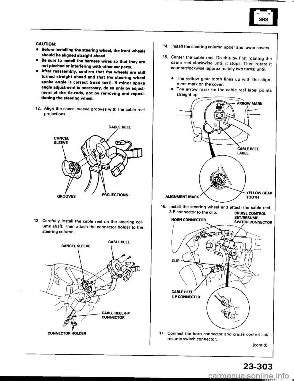
12. Align th€ cancel sleeve grooves with the cable reelprojections.
Carefully install th€ cable reel on the steering col-umn shaft. Then attach the connector holder to thesteering column.
CABLE REEL
CABI.I REEL
CONNECTOR HOLDER't7.
23-303
14.
t5.
Installthe steering column upper ano tower covers.
Center the cable reel. Do this by first rotating thecable reel clockwise until it stops. Then rotate itcounterclockwise (approximately two turns) until:
. The yellow gear tooth lines up with the align-ment mark on the cover.a The arrow mark on the cable reel label Dointsstraight up.
ABROW MARK
ALIGNMENT MARK
16. Install the steering wheel and3-P connector to the clip.
HORN CONNECTOR
YELLOW GEARTOOTH
attach the cable reel
CRUISE CONTROLSET/RESUME
Connect the horn connector and cruise control sevresume switch connector.
(cont'd)
Page 1409 of 1413

Supplemental Restraint System {SRSI
Cable Reel Replacement (cont'd)
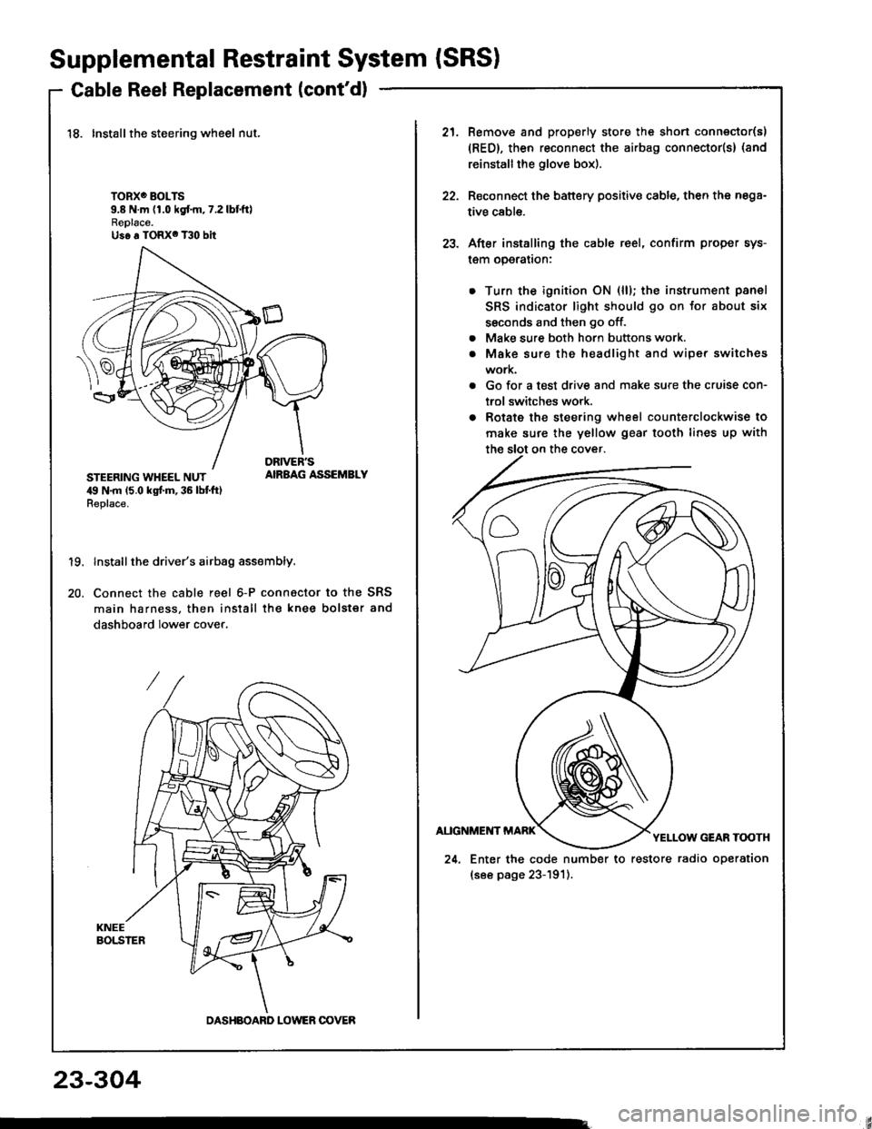
18. Installthe steering wheel nut.
TORXO BOLTS9.8 N.m (1.0 kgf.m,7.2lbtftlReplace.Us6 a TORX6 T30 bit
STEERING WHEEL NUT,19 N.m 15.0 kgt m, 36 lbt ft)Replace.
AIRBAG ASSEMBLY
19.
20.
Install the driver's airbag assembly.
Connect the cable reel 6-P connactor to the SRS
main harness, then install the knee bolster and
dashboard lower cover.
DASHBOARD LOWER OOVER
21.Remove and properly store the shon connector(s)
{RED}, then reconnect the airbag connector(s} (and
reinstall the glove box).
Reconnect the battery positive cable, then the nega-
tive cable.
After installing the cable reel, confirm proper sys-
l€m operalron:
Turn the ignition ON (ll); the instrument panel
SRS indicator light should go on for about six
ssconds and then go off.
Make sure both horn buttons work.
Make sure the headlight and wiper switches
work.
Go for a test drive and make sure the cruise con-
trol switches work.
Rotate the steering wheel counterclockwise to
make sure the yellow gear tooth lines up with
22.
23.
a
a
24. Enter the code number to restore radio operation
(see page 23-191).
23-304